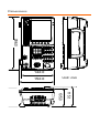
1
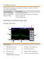
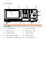
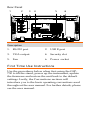
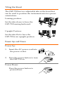
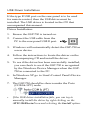
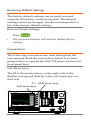
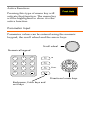
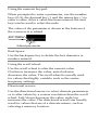
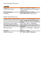
Spectrum Analyzer GSP-730 QUICK START GUIDE GW INSTEK PART NO. 82SP-73000M01 ISO-9001 CERTIFIED MANUFACTURER This manual contains proprietary information, which is protected by copyright. All rights are reserved. No part of this manual may be photocopied, reproduced or translated to another language without prior written consent of Good Will Corporation. The information in this manual was correct at the time of printing. However, Good Will continues to improve its products and therefore reserves the right to change the specifications, equipment, and maintenance procedures at any time without notice. Good Will Instrument Co., Ltd. No. 7-1, Jhongsing Rd., Tucheng Dist., New Taipei City 236, Taiwan. SAFETY INSTRUCTIONS This section contains the basic safety symbols that may appear on the accompanying user manual CD or on the instrument. For detailed safety instructions and precautions, please see the Safety Instructions chapter in the user manual CD. Safety Symbols These safety symbols may appear in the user manual or on the instrument. Warning Warning: Identifies conditions or practices that could result in injury or loss of life. Caution Caution: Identifies conditions or practices that could result in damage to the instrument or to other properties. DANGER High Voltage Attention Refer to the Manual Protective Conductor Terminal Earth (ground) Terminal Do not dispose electronic equipment as unsorted municipal waste. Please use a separate collection facility or contact the supplier from which this instrument was purchased. Power Cord for the United Kingdom When using the instrument in the United Kingdom, make sure the power cord meets the following safety instructions. NOTE: This lead/appliance must only be wired by competent persons. WARNING: THIS APPLIANCE MUST BE EARTHED IMPORTANT: The wires in this lead are coloured in accordance with the following code: Green/ Yellow: Earth Blue: Neutral Brown: Live (Phase) As the colours of the wires in main leads may not correspond with the coloured marking identified in your plug/appliance, proceed as follows: The wire which is coloured Green & Yellow must be connected to the Earth terminal marked with either the letter E, the earth symbol or coloured Green/Green & Yellow. The wire which is coloured Blue must be connected to the terminal which is marked with the letter N or coloured Blue or Black. The wire which is coloured Brown must be connected to the terminal marked with the letter L or P or coloured Brown or Red. If in doubt, consult the instructions provided with the equipment or contact the supplier. This cable/appliance should be protected by a suitably rated and approved HBC mains fuse: refer to the rating information on the equipment and/or user instructions for details. As a guide, a cable of 0.75mm2 should be protected by a 3A or 5A fuse. Larger conductors would normally require 13A types, depending on the connection method used. Any exposed wiring from a cable, plug or connection that is engaged in a live socket is extremely hazardous. If a cable or plug is deemed hazardous, turn off the mains power and remove the cable, any fuses and fuse assemblies. All hazardous wiring must be immediately destroyed and replaced in accordance to the above standard. GETTING STARTED This chapter provides a brief overview of the GSP-730, the package contents, instructions for first time use and an introduction to the front panel, rear panel and GUI. Main Features Performance • • 150kHz~3GHz bandwidth 100kHz resolution Features • Autoset with automatic floor level and span. Marker table function Limit line testing Split window display ACPR measurement OCBW measurement Automatic resolution bandwidth mode. • • • • • • Interface • • • • • • 480x640 color LCD display On-screen menu icons VGA video output RS-232C USB 2.0 Host port for data storage USB 2.0 Device port for the virtual com port communication Package Contents Please the package contents to ensure you have all of the following items: Part Number 82SP-73000E01 82SP-73000M01 Region Dep. Description User Manual CD Quick Start Guide (this document) Power cord x1 Cal. Certificate Display and Panel Overview Display Overview 2 3 1 8 4 7 6 5 Description 1. Reference level 2. Marker information 3. Function menu 4. Soft menu keys 5. Trace icons 6. Entry/Message area 7. Frequency / Bandwidth settings 8. Trace and waveforms Front Panel 1 2 3 Spectrum Analyzer 150 kHz 3 GHz Frequency Marker 4 BW Preset Span Peak Search Trace Hardcopy Amplitude Meas Display Hardcopy Setup Autoset Limit Line Memory System 5 F1 F2 F3 F4 F5 F6 7 8 9 GHz / Sec 4 5 6 MHz / mSec 1 2 3 kHz / mSec 0 dB 6 Enter BK SP RF INPUT 50 Ω DC ±25V MAX. +30dBm MAX. 10 9 8 Description 1. LCD display 2. Function keys 3. Menu keys 4. Hardcopy key 5. Scroll wheel 6. Arrow keys 7. RF terminal input 8. USB A port 9. Keypad and unit keys 10. Power button 7 Rear Panel 1 2 3 4 5 AC 100 50 6 240V 60 Hz 15W MAX. Description 1. RS-232 port 2. USB B port 3. VGA output 4. Security slot 5. Fan 6. Power socket First Time Use Instructions Use the procedures below when first using the GSP730 to tilt the stand, power up the instrument, update the firmware and restore the unit back to the default settings. Lastly, the Conventions sections will introduce you to the basic operating conventions used throughout the user manual. For further details, please see the user manual. Tilting the Stand The GSP-730 has two adjustable tabs at the front that can be used to position the instrument into two preset orientations. Leaning position: Set the tabs down to have the GSP-730 leaning backward. Upright Position: Set the tabs flat to have the GSP-730 in an upright position. Power Up and Down Power Up: 1. Insert the AC power cord into the power socket. 2. Press the power button to turn the GSP-730 on. Power Down: Press the power button to power down. Software Update The GSP-730 allows the software to be updated by end-users. Before using the GSP-730, please check the GW Instek website or ask your local distributor for the latest software. The update file, MAIN1.BIN, must be placed in the root directory of a USB flash drive. System Version: 1. Press 2. The system version is displayed on the SW Ver[F4] icon. System >Information[F4]. Software version Update Software: 1. Place the update file, MAIN1.BIN, into the root directory of a USB flash drive. 2. Insert the USB flash drive into the USB port on the front panel. 3. Press 4. Press Update Now[F3] to execute the update process. When the message “Programmed Successful” is displayed, the software has completed the update. • System >Update From USB Flash[F5]. 5. Reboot the system when the update procedure has finished by cycling the power button. 6. Check the software version again to confirm the update procedure. USB Driver Installation If the type B USB port on the rear panel is to be used for remote control, then the USB driver must be installed. The USB driver is located in the CD that accompanied this manual. Driver Installation: 1. Ensure the GSP-730 is turned on. 2. Connect the USB cable from the PC to the rear panel USB B port. 3. Windows will automatically detect the GSP-730 as a new device. 4. Follow the instructions to locate the driver on the accompanying CD and install the driver. 5. To see if the driver has been successfully installed, you can check to see if the GSP-730 is recognized by the Windows Device Manager when the GSP730 in connected to the PC. 6. In Windows XP go to: Start>Control Panel>Device Manager. 7. The GSP-730 should be shown under the Ports (COM & LPT) node: • If the USB driver installation fails, you can try to manually install the driver by right clicking on the AT91 USBSerial icon and selecting the Install option. Restoring Default Settings The factory default settings can be easily restored using the Preset key on the front panel. The default settings cannot be changed. See the user manual for a list of the factory default settings. Restore Default Settings: Press • . Preset The spectrum analyzer will load the default factory settings. Conventions The following conventions are used throughout the user manual. Read the conventions below for a basic grasp of how to operate the GSP-730 menu system and front panel keys. Soft Menu keys: The F1 to F6 function keys on the right side of the display correspond directly to the soft-menu keys on their left. F1 ~ F6 function keys Soft-menu keys GSP-730 Spectrum Analyzer 150 kHz 3 GHz Frequency Marker BW Preset Span Peak Search Trace Hardcopy Amplitude Meas Display Hardcopy Setup F1 F2 Autoset Limit Line F3 F4 F5 F6 Memory 7 8 9 GHz / Sec 4 5 6 MHz / mSec 1 2 3 0 kHz / mSec System dB Enter BK SP RF INPUT 50W DC ±25V MAX. +30dBm MAX. Input Parameter Values: Selecting this type of menu key will allow you to enter a new value with the numeric keypad or increment/decrement the value using the scroll wheel or number pad. See the parameter input description below for more details. Toggle State: Pressing this menu key will toggle the state. Notice that any soft-menu key that can be toggled will have the active parameter underlined. Toggle State & Input Parameter: Pressing this menu key will allow you to toggle the state of the function between on and off. When in the onstate, the parameter value can be manually edited. Use the numeric keypad to enter the new value or use the scroll wheel to increment/decrement the current value. Again, the setting that is underlined is the active setting. Sub Menu: Pressing the More menu key will enter a submenu. Sub Menu to select parameter Pressing this type of menu key will enter a submenu to select a parameter. Active Function: Pressing this type of menu key will activate that function. The menu key will be highlighted to show it is the active function. Parameter Input Parameter values can be entered using the numeric keypad, the scroll wheel and the arrow keys. Scroll wheel Numerical keypad 7 8 9 GHz / Sec 4 5 6 MHz / mSec 1 2 3 kHz / mSec 0 dB Enter BK SP Directional arrow keys Backspace, Enter keys and unit keys Using the numeric keypad: When prompted to enter a parameter, use the number keys (0~9), the decimal key (.) and the minus key (-) to enter a value. After a value has been entered, the unit keys can be used to select the units. The value of the parameter is shown at the bottom of the screen as it is edited. Ref:-30dBm Edited parameter Back Space: Use the backspace key to delete the last character or number entered. Using the scroll wheel: Use the scroll wheel to alter the current value. Clockwise increases the value, anti-clockwise decreases the value. The scroll wheel is usually used for values that highly variable, such as the center frequency settings. Directional arrows: Use the directional arrows to select discrete parameters or to alter values by a coarser resolution than the scroll wheel. Left/down decreases the value, right/up increases the value. The directional arrows are usually used for values that are of a discrete nature, such as selecting a memory location. SPECIFICATIONS The specifications apply when the GSP is powered on for at least 30 minutes under +20°C~+30°C. Frequency Specifications Frequency Range Setting Range Center Frequency Setting Resolution Accuracy Frequency Span Setting range Accuracy Resolution Bandwidth Setting Range 150kHz to 3GHz 0.1MHz within ±50kHz (frequency span : 0.3GHz to 2.6GHz, 20 ±5°C) 1MHz to 3GHz within ±3% (frequency span : 0.3GHz to 2.6GHz, 20 ±5°C) 30KHz, 100KHz, 300KHz, 1MHz, nominal -3dB bandwidth SBB Phase Noise -85dBc / Hz (typical, 500kHz offset, RBW : 30kHz, Sweep time : 1.5s,Span:1MHz@1GHz) Inherent Spurious Response less than -45dBc @ -40dBm Ref. Level (typical less than -50dBc) Amplitude Specifications Reference Level Input Range Accuracy Unit +20 to -40dBm Within ±2dB (1GHz);SPAN:5MHz dBm, dBV, dBµV Average Noise Level ≤ -100dBm (typical, center frequency : 1GHz RBW : 30kHz) Frequency Characteristics within ±3.0dB @300MHz~2.6GHz, within ±6.0dB @ 80~300MHz, 2.6~3GHz Input Input Impedance Input VSWR Input damage level Input connector 50ohm, nominal less than 2.0@input att≥10dB +30dBm (CW average power), 25VDC N connector Sweep Specifications Sweep Time Range Accuracy 300ms to 8.4s, auto (not adjustable) within ±2% ( frequency span : full span) General Specifications Interface RS-232C USB Connector VGA Output Display Sub-D female-D 9 pins USB Host/Device full speed supported Sub-D female 15 pins 640*480 RGB color LCD Other Specifications Operating Temperature 5 to 45°C (Guaranteed at 25 ±5°C, without soft carrying case) Operating Humidity less than 45°C / 90%RH Storage Temperature -20 to 60°C, less than 60°C / 70%RH Dimensions 296 (L) × 153 (W) × 105 (H) mm Weight Approx. 2.2kg Power Source AC 100~240V, 50/60Hz Dimensions GSP- 730 Spectrum Analyzer 150 kHz 3 GHz Meas Peak Search Marker Memory Display Trace BW Hardcopy Setup Hardcopy Preset Frequency Limit Line 2 5 8 3 6 9 kHz/ mSec MHz / mSec GHz / Sec Enter dB System Span 7 Autoset Amplitude 4 BK SP 1 0 RF INPUT50Ω DC ±25V MAX . +30 dBm MAX . Unit: mm 152.0 F1 F2 F3 F4 F5 F6 296.0 142.0 115.1 105.0 EC Declaration of Conformity We GOOD WILL INSTRUMENT CO., LTD. No.7-1, Jhongsing Rd., Tucheng Dist., New Taipei City 236, Taiwan GOOD WILL INSTRUMENT (SUZHOU) CO., LTD. No. 69, Lushan Road, Suzhou New District Jiangsu, China declares that the below mentioned product: GSP-730 Is herewith confirmed to comply with the requirements set out in the Council Directive on the Approximation of the Law of Member States relating to Electromagnetic Compatibility (2004/108/EC) and Low Voltage Equipment Directive (2006/95/EC). For the evaluation regarding the Electromagnetic Compatibility and Low Voltage Equipment Directive, the following standards were applied: ◎ EMC EN 61326-1: Electrical equipment for measurement, control and EN 61326-2-1: laboratory use –– EMC requirements (2006) EN 61326-2-2: Conducted and Radiated Electrostatic Discharge Emissions EN 61000-4-2: 2009 EN 55011: 2009+A1: 2010 Current Harmonic Radiated Immunity EN 61000-3-2: 2006+A1: 2009+A2: EN 61000-4-3: 2006+A1: 2009 2008+A2 :2010 Voltage Fluctuation Electrical Fast Transients EN 61000-3-3: 2008 EN 61000-4-4: 2004+A1: 2010 Surge Immunity ------------------------EN 61000-4-5: 2006 Conducted Susceptibility ------------------------EN 61000-4-6: 2009 Power Frequency Magnetic Field ------------------------EN 61000-4-8: 2010 Voltage Dip/ Interruption ------------------------EN 61000-4-11: 2004 ◎ Safety Low Voltage Equipment Directive 2006/95/EEC Safety Requirements: EN 61010-1: 2010, EN 61010-2-030: 2010