1
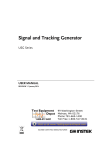
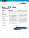
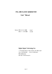
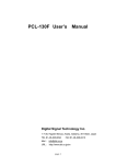
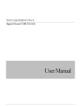
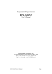
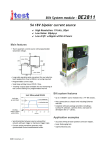
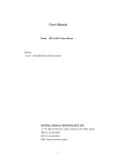
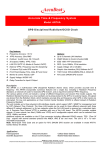
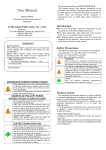
DDS-PLL SYNTHESIZER
DPL-2.5GF
USER’S MANUAL
DIGITAL SIGNAL TECHNOLOGY, INC.
1-7-30, HIGASHI BENZAI, ASAKA CITY
SAITAMA 351-0022 JAPAN
TEL : 81-48-468-6094 FAX : 81-48-468-6210
http://www.dst.co.jp/en
1
DPL-2.5GF is wide band signal generator utilizing DDS (Direct Digital Synthesis)
and PLL (Phase Locked Loop) technique. It provides pure signal output from
700MHz – 2.5GHz in 10Hz steps. The frequency can be controlled by serial data
which can be connected to PC communication port and can be memorized into
EEPROM and in case of setting the power off, and on again, the stored
frequency can be output. The temperature compensated internal 10MHz clock
provides high stability in wide temperature range
In case the accurate 10MHz clock is available externally, the frequency stability
can be improved. The half or quarter of the output frequency is available by
adding optional frequency divider.
■ Specification
Power supply
+5V±5% 100mA
+24V±10% 200mA
700MHz – 2500MHz
0 dBm ±3dB
50Ω
10Hz
less than –60dB (except harmonic)
more than –10dBc
Frequency range
Output level
Output impedance
Frequency resolution
Spurious
Harmonic spurious
Phase noise
700MHz
1000MHz
2500MHz
OFFSET from carrier center frequency
1KHz
10KHz
100KHz
-85dBc/Hz
-80dBc/Hz
-93dBc/Hz
-82dBc/Hz
-80dBc/Hz
-96dBc/Hz
-77dBc/Hz
-77dBc/Hz
-97dBc/Hz
Internal clock
temperature frequency stability
long term frequency stability
frequency accuracy
External reference input
External ref. Input impedance
Non-Volatile memory save times
Frequency control
Dimensions
±2.5ppm(0~50℃)
±3ppm per year
±2.5ppm@25℃(adjustable)
10MHz 0.5-5Vp-p
more than 10kΩ
more than 10,000
RS-232C async serial input, 9pin D-SUB
9600BPS, 8 bit without parity 1 stop bit
104x67x29mm
2
■
How to connect terminal
+24V power supply terminal
+5V power supply terminal
External 10MHz
REF INPUT
RS-232C port
OUTPUT PORT
Caution: The polarity of the power supply should be connected correctly not to
damage the DPL-2.5GF unit.
1. +5V power supply terminal
Connect 5V±5% the power supply having more than 100mA current capacity
2. +24V power supply terminal
Connect 24V±10% power supply having more than 200mA current capacity
3. External 10MHz reference clock input
Apply 10MHz reference clock in external clock mode. SMA connector is used.
4. RS-232C port
This is a signal control connector to set a frequency. The frequency is controlled
by RS-232C serial input and 9 pin D-Sub female connector is used.
5. Output port
This is a terminal of output signal. SMA connector is used.
3
■
OUTLINE
4
■
RS-232C port communication condition
Communication speed
Data length
Stop bit
Parity
Flow control
9600BPS Aysncronous
8bit
1bit
none
none
9 pin D-SUB pin ordering
Pin# Signal name Signal direction
Ref
DPL-2.5GF <-> terminal
1
CD
->
connected to DTR internally
6
DSR
->
connected to DTR internally
2
RD
->
7
RTS
<-
not used
3
TD
<-
8
CTS
->
connected to DTR internally
4
DTR
<-
“
CD,CTS,DSR “
9
RI
->
not used
5
GND
<->
It is possible to set frequency, using common PC communication software, for
example Hyperterminal and so on.
■
How to set frequency
The following message is returned when DPL-2.5GF is power on.
DPL-2.5GF OSCILLATOR VX.X
XXXXXXXX CLOCK MODE
*
XXXXXXXX shows the present selected clock mode. After prompt “* ” is
returned from DPL-2.5GF, enter frequency data. The frequency data has three
formats, MHz unit input, KHz unit input and 10Hz unit input.
When DPL-2.5GF received the data correctly and completed the frequency
setting, it returns “*” as a prompt and output the desired frequency. When the
data received in-correctly or some errors occurred during the transfer, it returns
“INVALID DATA”. Each time the frequency data is set consecutively, first make
sure whether “*” code is returned, then set new frequency.
5
Input on MHz unit
The following example shows the
unit.
2
3
32
33
hex
hex
data in case setting 2300.00000MHz in MHz
0
30
hex
0
30
hex
M
4D
hex
CR
0D
hex
The data below 100KHz is set at “0” automatically.
Input on KHz unit
The following example
unit.
2
3
32
33
hex
hex
shows the data in case setting 2300000.00KHz on KHz
0
30
hex
0
30
hex
0
30
hex
0
30
hex
0
30
hex
K
4B
hex
CR
0D
hex
The data below 100Hz is set at “0” automatically
Input on 10Hz unit
The following example shows the
unit.
2
3
0
0
32
33
30
30
hex
hex
hex hex
■
data in case setting 2300000000Hz on 10Hz
0
30
hex
0
30
hex
0
30
hex
0
30
hex
0
30
hex
CR
0D
hex
How to memorize the frequency
In order to memorize the current frequency into the built-in EEPROM, enter
“SAVE” command as shown below. “CURRENT FRQUENCY IS SAVED!”
message is returned, if the command is received correctly.
S
53
hex
■
A
41
hex
V
56
hex
E
45
hex
CR
0D
hex
How to change a reference clock source
Internal or external clock mode can be toggled by entering “EXT” command.
6
Enter the following command.
E
53
hex
X
41
hex
T
56
hex
CR
0D
hex
When the above command is received correctly, the following message is
returned in external clock mode.
“CURRENT CLOCK SOURCE =>EXTERNAL”
“Do you want to change clock source? ( Y/N )
Clock mode can be changed from external to internal by entering “Y”.
This clock mode is saved in EEPROM and fixed semi-permanently until next “
EXT” command is issued.
■
How to adjust the internal reference clock.
When the internal reference clock frequency is deviated, adjust as follows:
(1) Confirm whether the present clock mode is internal clock mode. If it is in
external clock mode, change to internal clock mode with “EXT” command.
(2) Connect to a high resolution frequency counter, and set a frequency such as
1000.00000MHz.
(3) Then enter “DBUG” command and DBUG menu will be shown below.
(4) Select “3: INTERNAL CLOCK FREQUENCY ADJUST” so that the following
message will be shown.
“FREQUENCY ADJUST (u or d) = > XXXX”
XXXXX is the current hexadecimal correction value which has no meanings.
Enter the following character to up or down the frequency with frequency
counter.
“u”
“d”
“U”
“D”
: To step the frequency up finely
: To step the frequency down finely
: To step the frequency up coarsely
: To step the frequency down coarsely
(5) Input “E” for the end of adjustment.
7
■
Cautions :
(1) Use the low rippled power supply. When the switching power supply is used,
use noise filter to reduce switching noise from the power supply.
(2) Pay attention to the accuracy of the power supply voltage because+5V power
supply voltage affects output level.
(3) In external clock mode, use the external 10MHz clock having the frequency
accuracy of less than 3 ppm.
(4) The external reference input is high impedance. In case of connecting with
50Ω coaxial cable, use 50Ω termination.
Descriptions of this manual are subject to change without notice.
No portion of this manual can be reproduced without the permission of DS Technology.
DS Technology assumes no liability for damages that may occur as a result of handling by users.
The contents of this manual do not apply to the warranty in executing an industrial property or other
rights, nor permission for the right of execution.
DS technology assumes no responsibility for the third party’s industrial property occurred from using
the circuits described in this manual.
Copy right 2000
DS Technology
All rights reserved
Printed in Japan
8