1
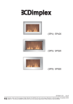
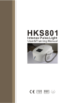
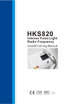
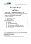
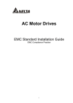
USER
MANUAL
MODEL 570/580
100Base-T (CAT-5)
Surge Protectors
Part# 07M570/580-B
Doc# 074091UB
Revised 2/16/96
SALES OFFICE
(301) 975-1000
TECHNICAL SUPPORT
(301) 975-1007
1.0 WARRANTY INFORMATION
2.0 GENERAL INFORMATION
Patton Electronics warrants all Model 570/580 components to be
free from defects, and will—at our option—repair or replace the product
should it fail within one year from the first date of shipment. This
warranty is limited to defects in workmanship or materials, and does not
cover customer damage, abuse or unauthorized modification. If this
product fails or does not perform as warranted, your sole recourse shall
be repair or replacement as described above. Under no condition shall
Patton Electronics be liable for any damages incurred by the use of this
product. These damages include, but are not limited to, the following:
lost profits, lost savings and incidental or consequential damages arising
from the use of or inability to use this product. Patton Electronics
specifically disclaims all other warranties, expressed or implied, and the
installation or use of this product shall be deemed an acceptance of
these terms by the user.
Thank you for your purchase of this Patton Electronics product.
This product has been thoroughly inspected and tested and is
warranted for One Year parts and labor. If any questions or problems
arise during installation or use of this product, please do not hesitate to
contact Patton Electronics Customer Service at (301) 975-1007.
2.1 FEATURES
• Multi-level surge protection
• Operation at Speeds up to 100 Mbps
• Optional 2,4,6 or 8 wire versions
• EIA/TIA TSB-40A Category 5 Compliant
• N.E.X.T. better than -43 dB at 100 MHz
• Shunts surges directly to chassis ground
1.1 SERVICE
• Easy to install
All warranty and non-warranty repairs must be returned freight
prepaid and insured to Patton Electronics. All returns must have a
Return Materials Authorization number on the outside of the shipping
container. This number may be obtained from Patton Electronics
Technical Service at (301) 975-1007. Packages received without an
RMA number will not be accepted.
Patton Electronics' technical staff is also available to answer any
questions that might arise concerning the installation or use of your
Model 570/580. Technical Service hours: 8AM to 5PM EST, Monday
through Friday.
2.2 DESCRIPTION
Devices that connect to Category-5 cabling systems are routinely
threatened by unwanted electrical energy (lightning, AC power
induction, ESD and more). Higher speed devices–such as those
operating at 100 Mbps–are especially vulnerable to the effects of these
hazards, which can include data loss and hardware damage.
The Patton Model 570 and 580 Series Surge Protectors provide
effective surge protection for devices operating in Category-5 Cabling
Systems. The Model 570 is specifically designed for point-of-use
installation; the Model 580 is designed to be installed at the building
entrance. Both models use a multi-stage Silicon Avalanche Diode
circuit, and will continue functioning while handling the appropriate IEC
801.5 surges applicable to their use (see the tables in Appendix B).
Both the 570 and 580 will additionally protect against surges up to and
exceeding 2kV/1kA in fail-safe mode.
Models 570 and 580 support a wide range of balanced interfaces
from RS-422 to 100Base-T. Highlights include a low insertion loss (less
than 0.4dB at 100MHz) and minimal near end cross talk (greater than
-43 dB at all frequencies up to 100 MHz). Grounding is accomplished
via an external ground strap that provides a separate unit-ground to
chassis-ground connection.
Warning: This product will not provide complete protection should your
equipment or building be subject to a direct lightning hit.
1
2
3.0 INSTALLATION
Patton's Model 570 & 580 surge protectors are easy to install and
are designed to operate transparently to your network. This section
describes connection procedures for both models.
3.1 PRODUCT APPLICATIONS
Both Models 570 & 580 protect all eight pins on the modular RJ-45
Cat-5 interface, and work in environments with data rates up to 100
Mbps. The following descriptions will give you a general guideline for
installing the units in your Cat-5 environment.
The Model 580 is also well suited for use in severe lightning areas,
heavy industrial environments, and installations with heavy machinery
in the direct vicinity of sensitive LAN equipment and cabling. Figure 2
(below) shows a typical application for the Model 580. For best results,
the braided grounding strap on the Model 580 should be attached to the
grounded metal frame of the device being protected. When installation
is made at a barrier, such as an external wall, the braided strap should
be connected to a nearby electrical ground.
Model 570 or 580
Exterior Wall
Electrical Panel
3.1.1 POINT-OF-USE APPLICATION (MODEL 570)
The Model 570 is designed for installation on LAN equipment in a
typical office environment (see Figure 1, below). For best results the
Model 570 should be connected as close as possible to the
communication port of the device to be protected (a 6 inch, Category-5
patch cable is provided with the Model 570). Also, the flat braided
grounding wire on the Model 570 should be attached to the grounded
metal frame of the device being protected.
Model 570
Model 570
Model 570 or 580
Local Hub
To
other
bldg.
or
floor
Model 580
Model 570 or 580
Figure 2. A typical barrier application for the Patton Model 580.
3.2 INSTALLATION PROCEDURES
In order to operate as designed, the Model 570 and 580 must be
connected correctly to your Cat-5 network. Please read all the
instructions below and follow them carefully.
Connection of the Model 570 or 580 to an I/O Port
Figure 1. A typical point-of-use application for the Patton Model 570.
1. Turn off equipment power and unplug (disconnect) the existing
connection between the UTP cable and the equipment’s I/O port.
3.1.2 BARRIER APPLICATION (MODEL 580)
The Model 580 is a more robust protector than the Model 570, and
is designed for use as a barrier protector on LAN equipment in campus
networks. Applications include cable runs between buildings, cable
runs between floors on multi-story structures, and as a higher capacity
replacement for the Model 570 (a 6 inch, Category-5 patch cable is
provided with the Model 580).
(continued)
(continued)
3
4
2. Install the Model 570/580 between the incoming UTP line and the
protected equipment (see Figure 3, below). This installation
requires a straight through Cat-5 patch cable with modular RJ-45
connectors (supplied with unit). Note: It doesn’t matter which end
of the Model 570/580 plugs into which cable.
Cat-5 patch cable to
protected equipment
(6 inches or less)
Cat-5 input
from network
Connection of the Model 580 at a Barrier (Wall, Bldg Entrance, etc.)
1. Disconnect the UTP cable from the wall jack or patch panel jack.
2. Install the Model 580 between the UTP line and the jack. This
installation requires a straight through Cat-5 patch cable with
modular RJ-45 connectors (supplied with unit). Note: It doesn’t
matter which end of the Model 580 plugs into which cable.
3. Locate an electrical ground nearest the jack. Often this will be on
an electrical panel or sub panel. If you cannot locate a nearby
electrical ground, contact Patton Technical Support at
(301) 975-1000 to discuss an alternative grounding solution.
Connection to
chassis ground
Figure 3. Installation of Model 570/580 Surge Protectors.
4. Connect the braided ground strap directly to the electrical ground
you have located. The best way to make this connection is to
attach the braided metal strap to a metal panel or wallplate screw
using a hex nut or screw.
Caution: Surge energy may run both directions on the ground
strap. To provide the best protection, it is essential that the ground
strap on the Model 580 be connected to an electrical ground.
3. Locate a metal chassis ground on the equipment to be protected.
This is often a hex screw on a D-shell or AUI connector.
Sometimes a metal back panel is attached by screws, one of which
can be used for chassis grounding. If you cannot locate a chassis
ground connection on your equipment, contact Patton Technical
Support at (301) 975-1000 to discuss an alternative grounding
solution.
4. Connect the braided ground strap directly to the chassis ground
connection you have located (see Figure 3, above). The best way
to make this connection is to attach the braided metal strap using a
hex nut or screw on your device.
Caution: Surge energy may run both directions on the ground
strap. To provide the best protection, it is essential that the ground
strap on the Model 570/580 be connected to the chassis ground of
the protected device. Do not lengthen the ground strap of the
Model 570/580 or connect to a ground other than chassis ground
unless instructed to do so by Patton Technical Support.
5
6
APPENDIX A
SPECIFICATIONS
Environment: Category-5 Interfaces that utilize the RJ-45
connector, including RS-422, 423, 10Base-T, Token Ring, Fast
Ethernet, 100Base-T and ATM
Connectors: RJ-45 Female
Response Time: Clamped to 13 V after 0.1 µs
Characteristic Impedance: 100 Ohms
NEXT Loss: Model 570 - worst pair Better than -46 dB at 100 MHz;
Model 580 - worst pair Better than -43 dB at 100 MHz
Surge Clamp Voltage: Model 570 - 13 V max with 1 KV Input;
Model 580 - 15 V max with 2 KV Input
Surge Rating: IEC 801.5 Standard Level
DC Clamp Voltage: Common Mode to Gnd, each line
7.5 V @ 50 mA; Differential mode, per pair 8.1 V @ 50 mA
APPENDIX B
INTERNATIONAL ELECTROTECHNICAL COMMISSION (IEC)
COMPLIANCE
Meets IEC standards 801.2, 801.4 and 801.5 (CE Mark)
Effective January 1996 the European Economic Community will
require that all electronic devices be tested and comply with all
applicable International standards relating to the product type and
category of use. Electromagetic Compatibility Directive 89/336/EEC
specifically addresses communication line surge protection devices,
since conformity to immunity standard EN50082-1:1992 is mandatory.
The EN50082-1:10992 standard incorporates International
Organization for Standardization (ISO) publications 801.2 and 801.4,
which describe Electrostatic Discharge and Electrical Fast Transient
requirements. ISO 801.5 describes Surge Immunity Requirements and
is expected to be adopted as a mandatory requirement under
EN50082-1 by the Technical Committee. in 1996. Any protector sold
into the international community must meet these standards. This
device has been tested* and found to comply with these standards as
evidenced by its CE mark.
IEC 801-5 Threat Levels as a Function of Class
Class
Sym. Lines Coupling Mode
Line-GND, Zs=42 Ohms
Insertion Loss: Less than 0.4 dB at 100 MHz (including connector)
1
Return Loss: Better than 14 dB
2
Group Delay: None, 1 MHz to 100 MHz
3
Series Resistance: Less than 400 milliohms
Grounding: External ground strap provides separate unit-ground to
chassis-ground contact
Dimensions: 2.25" x 1.69" x .75"
4
5
Wave
Forms
1.0 kV
24 A
1.0 kV
24 A
2.0 kV
48 A
(n/a)
(n/a)
4.0 Kv
95 A
(1.2 x 50 µs)
(1.2 x 50 µs)
Figure B-1. IEC Threat Levels as a Function of Class.
*Note: All test results are for the Model 570/580 alone, not including the
standard 6” patch cable that is normally shipped with the unit.
7
8
APPENDIX B
EIA/TIA TSB-40A COMPLIANCE
APPENDIX B (continued)
TSB-40A COMPLIANCE TESTING RESULTS
TYPICAL ATTENUATION MEASUREMENT
The Model 570/80 series surge protectors have been designed to
conform to stringent EIA/TIA TSB-40 standards as required for all
Category-5 connecting hardware. These standards specify the
capacitance and near end cross-talk (N.E.X.T) to insure proper
operation of ALL connected equipment. Specific test results are shown
in the tables on the following pages*.
TSB-40A COMPLIANCE TESTING RESULTS
TYPICAL NEAR-END CROSSTALK MEASUREMENT
Figure C-3. Attenuation measurements for Patton Model 570.
Figure C-1. N.E.X.T. measurements for Patton Model 570.
Figure C-4. Attenuation measurements for Patton Model 580.
Figure C-2. N.E.X.T. measurements for Patton Model 580.
*Note: All test results are for the Model 570/580 alone, not including the
standard 6” patch cable that is normally shipped with the unit.
9
10
APPENDIX B (continued)
TSB-40A COMPLIANCE TESTING RESULTS
TYPICAL RETURN LOSS MEASUREMENT
Figure C-5. Return Loss measurements for Patton Model 570.
Figure C-6. Return Loss measurements for Patton Model 580.
11