1
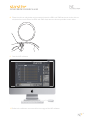
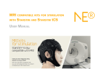
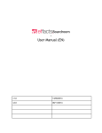
User
manual
v1.3
> Table of Contents
1. Intended use
3
2. Safety Information
4
3. Regulatory information
4
4. Use environment
4
5. Safety Warnings
5
6. Conditions of use
6
7. Contents of the box
6
8. Technical Specifications
7
9. NECBOX Device description
8
10. Assembling and using the kit
9
11. System Requirements
12
12. Signal quality check
13
13. Silver-Silver Chloride (Ag/AgCl) electrode instructions
14
13.1 Precautions for handling electrodes
13.2 Conditioning 13.3 Cleaning
13.4 Sterilization
13.5 Darkening
13.6 Storage
13.7 Malfunction
13.8 Noisy electrodes
13.9 Life expectancy
14
14
14
14
14
14
15
15
15
14. Neoprene cap cleaning and disinfecting instructions
15
15. NECBOX cleaning instructions
15
16. Battery operating/safety instructions
16
16.1 Charging the battery
16
17. Symbols used
17
18. EMC information
18
19. Change record
22
2
1. Intended use
StarStim is a transcranial current stimulation device and an EEG monitoring device, all in one.
The device is battery operated.
Brain stimulation can be used only under medical prescription or under the supervision
of an appropriate Ethics Committee as regulated in each country of intended use.
Transcranial Current stimulation (tCS) is a neurophysiological technique capable of modulating
the excitability of the neuronal tissue of the central and peripheral nervous system through
the application, for a finite time length, of an electrical field. This electric field is generated
by the application of weak electrical currents through the scalp and into the brain.
It has been demonstrated in recent years that the technique is safe and beneficial
if used within the known bounds of intensity, density and duration.
However, its application must be controlled by specialized medical personnel
able to guarantee the application of correct stimulation parameters.
StarStim must be always used according to applications already described in the literature.
In any other case, the supervision of a local Ethics Commitee or analogous
Body must be required for the experimental use of this device.
StarStim is specifically designed to be used only under medical prescription.
Because the treatment can be performed only following the prescription made by specialized
personnel, the current stimulation delivered by StarStim can be considered safe.
Read the User Manual carefully before using StarStim.
3
2. Safety Information
StarStim is a class IIa device according to the classification in the
Council Directive 93/42/CEE for medical devices.
It conforms to the following Standards and Directives:
• Directive 93/42/CEE for medical devices
• UNE-EN 60601-1:1993 + A1:1996 + A2:1996 + A3:1997 + A2/ERR:1999
• UNE-EN 60601-1-2:2008
• UNE-EN 60601-2-26:2004
3. Regulatory information
Manufacturer:
Neuroelectrics Barcelona SL
C/ Teodor Roviralta, 45
08022 Barcelona
Spain
Telephone: + 34 93 254 03 70
Brand:
StarStim
Models:
StarStim
4. Use environment
The StarStim system have been designed for the use in a
clinical environment, hospital or research center.
4
5. Safety Warnings
WW Note for clinical use: Brain stimulation
must be always used according
to medical prescription.
WW Brain Stimulation must be used AFTER
the prescription of a stimulation protocol
made by the specialized and qualified
medical personnel who owns and
operates the StarStim Software.
WW Before the brain stimulation is prepared,
please inform the prescribing clinician
or operator of the presence of any
pacemakers, intracranial electrodes,
implanted defibrillators, cranial pathologies
(e.g. holes, plaques) or any other
prosthesis. In these cases the use of
the device could become unsafe.
WW Always unplug the USB power supply
from the device prior to connecting
electrodes to the subject. The device will
not work when charging the battery.
WW Never use the device or install the
electrodes on the head of the patient
while connected to the power network.
WW The device must be used only
with Ag/AgCl electrodes for EEG
recommended by the manufacturer.
WW The electrodes for stimulation can be
Ag/AgCl or carbon rubber electrodes
with sponges soaked with saline
solution. They must be bigger than 3
mm2 to avoid high density currents.
WW The results of the measurements
WW The device is not protected against
WW The device must never be
WW The device is wireless and might be
must be analysed by a doctor or
specialist. No self medication should
be done based on this results.
opened or damaged.
WW The battery can only be replaced
by authorized personnel.
WW Before using, please check that the device
is undamaged and the packaging has not
been affected by transport or storage.
WW In the case of malfunction, immediately
contact the manufacturer or the distributor.
WW The device is not protected against
excessive moisture or immersion
in liquid. In the case of the device
becoming wet or damp, do not use it and
immediately contact the manufacturer.
WW Do not touch the device during stimulation
or while EEG monitoring is on.
other high frequency devices. To avoid
risks place the CMR/DRL as far as
possible from the s and return electrode
of the high frequency device.
affected by other RF devices.
WW The device needs special EMC precautions.
It needs to be used according to user
manual information regarding EMC.
WW The EMC emissions and immunity has
been tested using the 10-wire or 12-wire
34 cm cables provided with the system.
WW The use of cables or electrodes other
than the ones delivered with the
product might produce higher EMC
emissions and less EMC immunity.
WW The device cannot be used beside or piled
under other equipment. If such usage is
needed, check the normal configuration.
WW The device can only be used in
healthy skin without wounds.
5
6.Conditions of use
StarStim must be used in normal temperature and pressure conditions (T range:
10-45°C, humidity 20-90%, atmospheric pressure 700-1000 hPa).
7.Contents of the box
When you first open the box you will see the following items:
• Neoprene cap
Under the foam cover you will find the rest of the kit:
• Neuroelectrics Control Box (NECBOX )
• 10-wire cable with the electrode back-ends
• Electrode front-ends
• Battery charger
• NE headband
• NE cap
• USB containing this manual and NIC software installer
(Neuroelectrics Instrument Control Software),
• Curved syringe with gel (mandatory for the PG + PGF and optional for the electrodes)
6
8.Technical Specifications
EEG functionality
• Number of Channels: 8 Channels
• Bandwidth: 0 to 125 Hz
• Sampling rate: 500 SPS
• Resolution: 24 bits – 0,05 microVolt
• Measurement Noise: < 1 uV RMS
• Input impedance: 1000 Mohm minimum
• Allows for Stimulation simultaneously
Stimulation functionality
• Number of channels: 8 channels
• Types of Stimulation: tDCS, tACS, tRNS, sham
• Current: maximum of plus/minus 2mA per electrode
• Current accuracy: < 10% (<1% after calibration)
• Current precision: <1 µA
• Configurable Ramp-up and Ramp-down time
• Current configurable independently for each channel
• Voltage: up to + - 15 V (30 V of stimulation potential)
• Variance of tRNS stimulation: < 640 uA
Other Technical Specifications
• Communication: Bluetooth 2.1
• Output: EDF+, ASCII data files or tcp/ip raw data streaming
• 3 axes accelerometer
• microSD card for off-line storage
• Operating time: 8 hours for EEG only
• Dimensions: 60 x 85 x 20 mm
• Weight: 65 g
• Compatible with Windows 7, Windows Vista, Windows XP, MAC OS X
7
9.NECBOX Device description
Description
1
1 USB connector. Only for charging
the battery. Must not be connected
when doing an EEG recording or
brain stimulation. The device will
not operate while charging.
2 Power ON switch. O indicates OFF
position and allows for charging
of the battery. I indicates ON
position (no charging possible).
2
3 MicroSD card socket
4 8 EEG/Stimulation channels
connector and reference signal
5 Not used in StarStim
The electrodes are connected here using
only the cables provided with the system.
5
4
3
6 LED indicates normal operation.
7 Velcro to attach the device to the cap.
8 Technical specifications label.
Includes Serial Number (a) and
MAC address for the device.
6
7
8
(a) The SN contains the date of manufacturing of the NECBOX in the format EYYYYMMDD
8
10. Assembling and using the kit
1 Install front-ends in the neoprene cap or the neoprene band in the desired
positions (use software instructions if you want to use a preset montage).
2 Put the cap or the band on the subject’s head with the electrode front-ends installed.
3 Place the NECBOX at the rear of the cap attached by means of the Velcro.
4 Connect the device cable to the NECBOX.
9
5 Insert gel (if using wet, gel electrodes) until it reaches the scalp of the subject.
6 Prepare the connections cable provided. The cable consists of eight EEG
electrodes numbered 1 to 8 and two reference electrodes labelled DRL
and CMS that act as drive circuit and common mode sensing.
7 Clip on the back-ends to the front-ends at the desired positions using channels 1 to 8.
10
8 Place the stick-on electrodes at the mastoid. Attach the DRL and CMS back-ends to the stick-on
electrode front-ends. Place the DRL and CMS electrodes as close as possible to each other.
9 Start the NIC software.
10 Refer to the software user manual for the usage of the NIC software.
11
11.System Requirements
•
•
•
•
Windows XP/Vista (32/64 bits) or MAC OS X (Intel) (=> Snow Leopard)
1GB RAM or more
Bluetooth adapter or USB 2.0 port
CPU Pentium D or better
12
12. Signal quality check
Before any recording the quality of the signal should be checked to ensure the correct measurements.
Signal drift
Before the EEG establishes a good redox reaction on each electrode,
the signal recorded might have a large DC drift.
This DC drift could affect the results recorded and should be avoided.
In the figure, a signal with a significant amount of drift is compared to a normal signal.
Normal signal
Signal with high drift
Contact impedance
Before any stimulation the software checks the contact impedance of each
electrode. If the impedance is higher than the normal values, the stimulation
protocol can’t be started. If an electrode has a very high contact impedance or shows high noise at the
signal, it should be changed because it has reach the end of its life.
Noisy electrodes
If the signal shows too high drift or noise, the electrodes might be at the end of their lives.
The figure shows a signal with a considerable noise.
13
13. Silver-Silver Chloride (Ag/AgCl) electrode instructions
13.1 Precautions for handling electrodes
Electrodes should not come into direct contact with metals as this may cause corrosion.
Avoid touching or contaminating the bare electrode surface as dirt can increase
calibration times. Use of corrosive chemicals will damage the electrodes.
13.2 Conditioning
To minimize DC offset and drift, place the electrodes in the working position 5
minutes before starting the measurement. The electrodes need some time to achieve
electrochemical equilibrium with the skin and electrolytes in the human body.
13.3 Cleaning
Silver-silver-chloride (Ag/AgCl) electrodes behave like sponges: they absorb water and
electrode gel. The deeper the water/gel has penetrated the electrode, the longer it will take
afterwards for the water to evaporate. As long as your electrodes are ‘wet’, corrosion will take
place. This corrosion process will, in the long run, make your electrodes noisier. That’s why
it’s important to clean the electrodes immediately after use and then let them dry.
Use warm tap water to rinse the gel from the electrodes (make sure to keep the
connector dry). Warm water (up to 50 degrees Celsius) will dissolve the gel more quickly.
Use a soft brush for removing gel residues from the electrodes only if absolutely necessary.
Softly dry the electrodes with a paper towel or let them hang to dry. Only use soap if water
does not seem to clean the electrodes properly. Never use solvents (e.g. acetone), acids
or alkaline. Do not let the electrodes dry without being cleaned first. When the electrodes
dry while covered with gel/salt/minerals, the cleaning process will be more difficult.
13.4 Sterilization
When sterilization is required, only gas or liquid agents should be employed. Disinfectants
containing mercury, phenols, bromine, iodine, zinc, tin and organo-metallic compounds should
be avoided. The electrodes and cable insulation will not withstand steam sterilization.
13.5 Darkening
Silver chloride is light-sensitive. Exposure to light will darken the electrode surface. This will not impair
the electrode performance since the largest interstitial Ag/AgCl matrix is not reached by light.
13.6 Storage
Electrodes should be handled with care. They must not be stored in contact with
metals, especially such active metals as iron or aluminium. Also, substances that
could affect the electrochemical characteristics should be avoided. Bare electrodes
should be stored in a clean, dry and dark container (plastic or glass).
14
13.7 Malfunction
If an electrode is not operating as specified and you experience noise, then
please follow the directions below concerning noisy electrodes.
13.8 Noisy electrodes
A continuously noisy electrode generally means that it has reached its end of life. You
can extend the life a little bit by using a grain 600 or higher waterproof abrasive paper to
polish the electrode tip. Use very soft circular movements, preferably no more than 2-3
times on the same area, removing an even, very thin layer across the entire surface.
13.9 Life expectancy
Ag/AgCl sintered electrodes have a limited life span. This is caused by several processes such
as corrosion, the dissolving of the chloride in the pellets and the wearing of the pellet during the
cleaning process. Eventually the colour of the pellets will change from grey/brown (silver–chloride) to
silver, due to the loss of the chloride. The AgCl slowly dissolves in gel and water during the cleaning.
Eventually, this leaves only silver behind. The resulting pure silver electrode has much higher drift and
noise characteristics than the original Ag/AgCl electrode. At this point replacement is recommended..
14. Neoprene cap cleaning and disinfecting instructions
After each use the neoprene cap or the neoprene band should be cleaned and disinfected.
Use warm tap water to rinse the gel and some ivory soap to clean the cap.
Dry the cap consciously using paper towel.
Spray the cap with disinfectant and let sit for 10 minutes.
Rinse cap thoroughly.
Hang up the cap to dry.
15. NECBOX cleaning instructions
After each use the NECBOX should be cleaned using a dry paper towel.
15
16. Battery operating/safety instructions
16.1 Charging the battery
The battery can only be charged when the power ON switch is at the OFF position.
To charge the battery, the following specifications have to be meet:
• 5V nominal output (4,25 – 7)V
• 1 A current output
• Battery charger complies according Stardard IEC-EN 60601-1
The battery charger has to be connected to the microUSB
connector located at the rear part of the NECBOX.
• The battery state of charge is measured by the software while the device is powered ON.
• The charging LED located near the connector shows colour yellow
when charging and green when it’s fully charged.
• It should be noted that the battery will be over-discharged if the device is not used for a long
time. In order to prevent over-discharging, the battery should be charged periodically.
• Over-discharging may cause loss of cell performance, or damage battery function.
• Expected life cycle> 500 cycles > 70 % of initial capacity.
• Charging with a higher voltage than specified may cause damage to cell.
• The usual time to charge a battery from the cut off voltage to the maximum capacity is around 2
hours, but it depends on every specific battery (battery life and memory is a function of time).
• The system can be connected to any Class 2 electrical installation.
Operating temperature
Charging: 0ºC to 45ºC
Discharging: -20ºC to 60ºC
Storage
temperature
NECBOX
electrical specifications
1 year
at -20ºC to 35ºC
Charging
Voltage input nominal: 5V DC
Voltage input min/max: 4,25 – 7 V
Power input: 5 W
Current output:
2mA per channel. + - 15V in
Frequency: 0 -0250 Hz none
16
17. Symbols used
Simbol
Description
IEC 60417-5333 BF type applicable part
according to UNE-EN 60601-1=2008
ISO 7010-W001 Warning signal according to UNE-EN 60601-1=2008
Parts marked with this symbol are not protected against defibrillator.
IEC 60417-5008 Switch OFF according to UNE-EN 60601-1=2008
IEC 60417-5007 Switch ON according to UNE-EN 60601-1=2008
ISO 7000-2498 Serial Number according to UNE-EN 980
Device manufacturer symbol according to UNE-EN 980
ISO 7000-1641 read instructions before use
symbol according to UNE-EN 980
ISO 7000-2606 do not use device if product or packaging
have been damaged symbol according to UNE-EN 980
Do not throw StarStim in generic waste symbol.
WARNING! When you want throw away the device, NEVER throw it
in the trash, but go to the RECYCLABLE POINT or the nearest waste
collection for further treatment, thus contributing to environmental care.
CE marked device certified by the Notified Body
n. 0120 of the European Community.
17
18. EMC information
The StarStim is suitable for use in the specified electromagnetic environment.
The costumer and/or user of the StarStim should ensure that is used
in an electromagnetic environment as described below:
Emissions Test
Compliance
Electromagnetic
Environment Guidance
Group 1
The StarStim uses RF energy only
for its internal function. Therefore, its
RF emissions are very low and are
not likely to cause any interference
in nearby electronic equipment.
RF Emissions
CISPR 11
RF Emissions
Class B
CISPR 11
Harmonic Emissions
Class A
IEC 61000-3-2
The StarStim is suitable for use in all
establishments, including domestic
establishments and those directly
connected to the public low-voltage
power supply network that supplies
buildings used for domestic purposes.
Voltage fluctuations/flicker emissions
Complies
IEC 61000-3-3
18
The StarStim image intensifier is suitable for use in the specified electromagnetic environment.
The customer and/or the user of StarStim image intensifier should ensure that it is used in an
electromagnetic environment as described below:
Immunity Test
IEC 60601-1-2
Test Level
Compliance
Level
Electrostatic
discharge (ESD)
6 kV contact
6 kV contact
8 kV air
8 kV air
IEC 61000-4-2
Electrical fast
transient/burst
IEC 61000-4-4
Surge
IEC 61000-4-5
Voltage
dips, short
interruptions and
voltage variations
on power supply
input lines
IEC 61000-4-11
Power frequency
(50/60 Hz)
magnetic field
IEC 61000-4-8
2 kV for power
supply lines
1 kV for input/
output lines
1 kV differential
mode
2 kV for power
supply lines
N/A
1 kV differential
mode
2 kV common
mode
N/A
<5%U
(>95% dip in U )
for 0,5 cycle
<5%U
(>95% dip in U )
for 0,5 cycle
40% U
(60% dip in U
) for 5 cycles
40% U
(60% dip in U
) for 5 cycles
70% U
(30% dip in U )
for 25 cycles
70% U
(30% dip in U )
for 25 cycles
<5%U
(>95% dip in
U ) for 5 sec
<5%U
(>95% dip in
U ) for 5 sec
3 A/m
3 A/m
Electromagetic
Environment Guidance
Floors should be wood, concrete,
or ceramic tile. If floors are covered
with synthetic material, the relative
humidity should be at least 30%,
Main power quality should be
that of a typical commercial
and/or hospital environment.
Main power quality should be
that of a typical commercial
and/or hospital environment.
Main power quality should be that
of a typical commercial and/or
hospital environment. If the user
of the StarStim requires continued
operation during power main
interruptions, it is recommended
that the StarStim image intensifier
be powered from an uninterruptible
power supply or a battery.
If image distortion occurs, it may
be necessary to position the
StarStim image intensifier further
from sources of power frequency
magnetic fields or to install magnetic
shielding. The power frequency
magnetic field should be measured
in the intended installation location
to ensure that it is sufficiently low.
Note: U is the A/C main’s voltage prior to application of the test level.
19
The StarStim is suitable for use in the specified electromagnetic environment. The customer and/
or the user of StarStim should ensure that it is used in an electromagnetic environment as described
below:
Immunity
Test
IEC
60601-1-2
Test Level
Conducted RF
IEC 61000-4-6
3 Vrms
50 kHz to
80 MHz
Compliance
Level
3 Vrms
Electromagetic
Environment Guidance
Portable and mobile RF communications
equipment should be used no closer
to any part of the StarStim, including
cables, than the recommended
separation distance calculated
from the equation appropriate for
the frequency of the transmitter
Recommended
Separation Distance
d=1,2√P
d=1,2√P 80 MHz to 800 MHz
d=2,3√P 800MHz to 2,5 GHz
Radiated RF
IEC 61000-4-3
3 V/m
80 MHz to
2,5 GHz
3 V/m
80 MHz to
1 GHz
where P is the maximum output
power rating of the transmitter
in watts (W) according to the
transmitter manufacturer and d
is the recommended separation
distance in metres (m).
Field strengths from fixed RF
transmitters, as determined by an
electromagnetic site survey (a),
should be less than the compliance
level in each frequency range (b).
Interference may occur in the
vicinity of equipment marked
with the following symbol:
(a) Field strengths from fixed transmitters, such as base stations for radio (cellular/cordless) telephones and land mobile radios, amateur radio,
AM and FM radio broadcast , and TV broadcast cannot be predicted theoretically with accuracy. To assess the electromagnetic environment
due to fixed RF transmitters, an electromagnetic site survey should be considered. If the measured field strength outside the shielded location
in which the StarStim is used exceeds the applicable RF compliance level above, the StarStim should be observed to verify normal operation. If
abnormal performance is observed, additional measures may be necessary, such as re-orienting or relocating the StarStim
(b) Over the frequency range 150 kHz to 80 MHz, field strengths should be less than 3 V/m.
NOTE 1 These guidelines may not apply in all situations. Electromagnetic propagation
is affected by absorption and reflection from structures, objects and people.
20
The StarStim is intended to be used in a controlled radiated RF environment. The user of
the StarStim can help to prevent the electromagnetic interferences keeping a minimum
distance between the portable RF device (transmitter) and the StarStim as recommended
below, according to the maximum output power of the communications device.
Separation distance metres
Rated Maximum
Output
Power of
Transmitter
watts
150 kHz
to 80 MHz
d=1,2√P
150 kHz
to 800 MHz
d=1,2√P
800 MHz
to 2,5 GHz
d=2,3√P
0.01
0,12
0,12
0,23
0.1
0,38
0,38
0,73
1
1,2
1,2
2,3
10
3,8
3,8
7,3
100
12
12
23
For transmitters rated at a maximum output power not listed above, the separation distance
can be estimated using the equation in the corresponding column, where P is the maximum
output power rating of the transmitter in watts (W) according to the transmitter manufacturer.
NOTE These guidelines may not apply in all situations. Electromagnetic propagation
is affected by absorption and reflection from structures, objects, and people.
21
19. Change record
Issue
Date
Changes made
Author
1.0
14/02/12
First version
Guillem Mitjà
1.1
19/03/12
Some minor corrections
Guillem Mitjà
1.2
13/04/12
Update after 60601 non-confirmities
Guillem Mitjà
1.3
26/07/12
Charging LED added
Guillem Mitjà
22
Teodor Roviralta 45
08022 Barcelona - Spain
Tel.+34 93 254 03 66
[email protected]
www.neuroelectrics.com
23