1
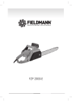
GB SILVERCAST-C Middle Frequency Centrifugal Casting Machine Instructions for Use Pi dental Ltd. Instructions for use Contents 1. 1.1 1.2 1.3 1.4 1.5 1.6 1.7 1.8 1.9 Safety instructions Intended use Symbols indicating risk Guarantee and liability Obligations of the authorized user Obligations of the personnel General information for the safe use of the equipment High risks Packaging Package contents 2. 2.1 2.2 Description of the Silvercast induction casting machine Function Assembling the machine 3. 3.1 3.2 3.3 Installation Positioning the machine Connecting the water supply in the laboratory Electrical installation in the laboratory 4. 4.1 4.2 4.3 4.4 4.5 4.6 Setting up and operation Inserting the casting ring and balancing the centrifugal arm Heating cycle Casting procedure Opening the casting chamber lid and removing the casting ring Switching off the casting machine Using the stop button 5. 5.1 5.2 5.3 5.4 Maintenance Cleaning the water inlet Cleaning the casting machine Crucible care Error indicators 6. Technical data 7. EC Conformity Declaration 2 GB Instructions for use 1. Caution: 1.1 GB Safety instructions Before switching the machine on, read through these instructions carefully. Intended use Silvercast induction casting machine is intended solely for dental laboratory use, for melting and centrifugally casting all conventional dental alloys with the exception of titanium. This machine should only be used for the intended purpose. The producer refuses any liability for damages originating from any other use of the machine. Intended use also includes adhering to the instructions for use as well as servicing and carrying out maintenance work at regular intervals. 1.2 Symbols indicating risk The following symbols are used in the instructions to indicate risks. Warning Indicates a potential danger to the life and health of the person. Disregarding this sign can critically affect a person’s health and may even result in injuries leading to death. Caution Indicates a potentially dangerous situation. Disregarding this sign can result in minor injury or damage to the equipment. 1.3 Guarantee and liability The manufacturer provides 2 years guarantee for the appliance with the serial number indicated on the last page of this document according to the General Conditions of Sale and Delivery. Guarantee and liability claims for damages to persons or equipment are invalid if the damage is found to have been resulted from any of the following cases: improper installation, operation, assembly or maintenance of the machine use of the machine other than for the purpose intended operation of the machine with faulty safety equipment or improperly installed or nonfunctioning safety and protective devices disregarding the Instructions for Use relating to transport, storage, assembly, operation and maintenance of the machine inadequate monitoring of the parts exposed to wear and tear unauthorized structural alterations to the machine repair carried out improperly. 3 Instructions for use 1.4 GB Obligations of the authorized user The authorized user is obliged to make sure that all those who operate the machine are familiar with the safety regulations and accident prevention and have been instructed on how to operate the machine have signed having read and understood the safety precautions and instructions for use have been instructed on the current regulations for the accident prevention. 1.5 Obligations of the personnel Before commencing any work, all those who operate the machine are obliged to adhere to the basic regulations regarding safety at work to sign having read and understood the safety instructions and instructions for use. 1.6 General information for the safe use of the equipment Do not modify the machine in any way. The machine should not be used if it is in any way faulty. Keep the working area clean. Untidiness at the workplace increases the risk of accidents. Do not reach into the machine while it is running. Do not open the machine until the casting arm is at rest. The casting chamber lid cannot be opened when the arm is rotating. For safety reasons, use only accessories and materials recommended by the instructions. Using materials other than those recommended in the instructions constitutes an accident risk for the operator and cannot therefore be regarded as intended use. Always disconnect the machine from the mains before commencing any maintenance work. 1.7 High risks Warning: The machine operates generating middle frequency electromagnetic waves and should not be operated by anyone having a heart pacemaker. Warning: Risk of burns on contact with the crucible or mould ring. Always use tongs to remove the hot mould ring after casting. 4 Instructions for use GB Warning: Risk of fire! Do not place any flammable object in the casting chamber. Warning: Always use protective goggles when observing the molten metal. Warning: Only alloys mentioned under 1.1 should be melted. Melting and casting light metals, such as aluminum, magnesium and titanium, can be particularly dangerous. 1.8 Packaging The packaging protects the machine during transit, but provides only limited protection against wet, heat and any mechanical force. The packaging should be disposed of in the proper manner observing the local environmental regulations. 1.9 Package contents 1 pc. 1 pc. 1 pc. 3 pcs. 1 set 1 set Silvercast induction casting machine Instructions for Use with CE Conformity Declaration ¾”end fittings, inner Ø 8 mm clips mould container (6 sizes: size 1-5 + 1 pieces of X size) mould ring (6 sizes: 4 parallel of tear-up system with rubber plate + 2 conical Dentaurum system usable from both sides, with plastic plate. 5 pcs. plastic funnel 1 pc. crucible for non-precious alloys 2. Description of the Silvercast induction casting machine 2.1 Function Silvercast is a compact, easy to operate induction casting machine for melting and casting all dental alloys with the exception of titanium and titanium alloys. It is ideal for use in smaller commercial laboratories as well as in private practice laboratories because it can be operated manually and has a variable heating control. On the other hand, large laboratories can make good use of it too, as its cooling system and capacity supports continuous operation. The machine operates based on the principle of energy transfer used in transformers and known as induction. By creating a middle-frequency magnetic field, a secondary current is produced through induction flows on the surface of the metal to be melted and this current is transformed into heat which then melts the metal. 5 Instructions for use GB The eddying currents created in the molten metal ensure that the metal is thoroughly mixed. The subsequent centrifugal casting into an investment also helps to produce a homogeneous mould. The main advantages of Silvercast induction casting machine are: 2.2 high melting capacity with low energy consumption homogeneous melting and casting minimum material loss less finishing required easy operation compactness easy maintenance. Assembling the machine The main part of the machine is a medium-frequency generator which is encased in a sheetsteel housing. The generator meets the requirements of the electromagnetic tolerance. The middle-frequency generator produces a 110 kHz electromagnetic field which heats and mixes the molten metal to a very homogeneous consistency. The induction coil (illus. 2,5) is watercooled and protected against overheating. The centrifugal arm (illus.2) in the casting chamber holds the crucible and the mould ring. The centrifugal arm has a counterweight to ensure smooth, quiet running. The induction coil (heating element) in the lower section of the chamber rises automatically to encircle the crucible when the program is started. After the heating phase, when the Casting button is pressed, the induction coil is lowered and the casting cycle commences. The melting process can be observed through a protective glass (illus. 2,1) which is integrated in the cover lid. 3. Installation 3.1 Positioning the machine Place the machine on a solid base, for example on a sturdy table, and set level. The installation place should be clean and as free from dust as possible. Caution: A minimum gap of 20 cm should be left between the casting machine and any appliances on either side. This ensures that the machine is well ventilated. Furnaces or other equipment emitting heat should not be placed next to the casting machine. 3.2 Connecting the water supply of the laboratory A fabric-reinforced water inlet pressure hose with ¾” threaded end fitting is used to supply water from the stopcock (illus.1) to the Water in connection on the back of the machine. 6 Instructions for use GB A hose with an inner diameter of 8 mm is used to drain the water from the hose nipple on the back of the machine into a siphon or directly into the domestic water drainage system. Ensure that there is no back pressure when the water is being drained. Caution: Check the water supply pressure if necessary before connecting the machine. Ensure that the water pressure does not fall below 3 bars and does not exceed 8 bars, even in summer. A water coolant pump unit should be fitted if the water pressure is too low. If the water pressure exceeds 8 bars, a pressure reduction valve should be fitted to the Water in connection of the machine. Caution: If the water supply system is known to build up deposits or collect dirt, a filter must be fitted to prevent the water sensor malfunctioning. 3.3 Electrical installation in the laboratory The casting machine should be connected exclusively into a 230 V earthed socket which is equipped with a 16 Amp circuit breaker or a 16 Amp slow-blow fuse. Warning: All electrical work on the socket or electricity supply and fuses may only be carried out by a qualified electrician. Automatic Fuses 2x16A Water out Type label Water in through ľ´´ hose Network connection 230V 50/60HZ Water draining Water supply from the city supply Illustration 1: Back of the machine with connections 7 GB Instructions for use 4. Setting up and operation 4.1 Inserting the mould ring and the crucible After it has been correctly installed, the machine can be set up for casting. Before each casting cycle the mould container matching by size with the mould ring and the crucible should be inserted in its place. 7. Casting chamber cover 5. View glass 6. Main switch 2. Crucible holder 1.Mouldframe 4. Induction coil 8. Mould container 3. Cradle Illustration 2: Casting chamber with centrifugal arm First open the stopcock of the water supply. Switch the machine on with the ON/OFF switch (illus. 2.6). An audible signal is heard when the machine is switched on and all the indicators light up briefly as a check that the LEDs are functioning properly. The green READY indicator (illus. 3.1) lights up when the water is circulating properly. Place the mould container matching by size with the mould ring into the cradle (illus. 2.3). Place the crucible with the ingots into the crucible holder (illus. 2.2) in the centrifugal arm with the casting spout pointing towards the mould ring. If the heating cycle is not to be carried out immediately, the machine can be switched off with the ON/OFF switch. 8 GB Instructions for use 4.2 Heating cycle The actual casting procedure can be carried out after the mould ring has been removed and the wax has been burnt out. Note: The hot mould ring can either be placed in the mould container just before starting the melting procedure or after the ingots have been preheated in the crucible using the preheating function. This prevents the mould ring cooling down too much. Caution: Danger of burn when touching the crucible or the mould ring. Always use tongs to remove the mould ring after the casting cycle. 1. Ready indicator 2. Heating indicator 7. Alloy selection 3. Error indicator 4. Cover status indicator 8. Program start button 5. Heating power regulation 9. Casting button 6. Stop button Illustration 3: Operating panel Check the water coolant supply before starting the heating cycle. Switch the machine on at the ON/OFF switch (illus. 2,6). An audible signal sounds when the machine is switched on and all the indicators light up briefly as a check that they are functioning properly. Then the green READY indicator (illus. 3,1) lights up. Place the crucible with the ingots into the crucible holder (illus. 2,2) with the casting spout pointing towards the casting ring. Note: Use a graphite insert in the crucible when melting precious metals with the exception of palladium alloys. 9 Instructions for use GB Preset the heat using the HEATING POWER regulator (illus. 3,5). Note: The HEATING POWER regulator should be set for each type of alloy and according to the amount of metal required so that during the 30 second preheat program the metal is still not fully melted. Set the centrifugal force using the ALLOY SELECTION switch (illus. 3,7). The setting depends on the type of alloy (precious or non-precious). Turn the centrifugal arm so, that the crucible is just above the induction coil. At this position you hear a continuous audible tone. Press the PROGRAM START button (illus. 3,8). The induction coil rises automatically to encircle the crucible for melting. Close the chamber cover. The red CLOSED sign (illus. 3,4) lights up and the yellow HEATING sign (illus 3,2) shows that the heating function is automatically activated. The metal begins getting melted after approx. 25 seconds. The melting procedure should only be observed through the protective glass (illus. 2,5). The HEATING POWER regulator (illus. 3,5) is used to regulate the heat during melting. When the metal is pre-molten, the casting chamber cover can be opened and the hot mould ring can be placed in the mould container. Use tongs to place the hot mould ring in the cradle (illus. 2,3). Position the mould ring so, that the flow is at the same height as the crucible spout. The centrifugal arm is balanced automatically (refer to section 4.1). Then close the casting chamber cover (illus. 2,7). The red CLOSED indicator (illus. 3,4) lights up when the cover is closed and the heating resumes automatically showed by the yellow HEATING indicator (illus. 3,2). Keep the casting chamber cover closed until the metal is molten and is ready for casting. Caution: Risk of burns. The heating cycle can produce high temperatures in the casting chamber. Note Press the red STOP button or open the cover to interrupt the heating cycle (refer to section 4.6) 4.3 Casting procedure After the casting chamber cover has been closed, the heating cycle resumes automatically. The yellow HEATING indicator (illus. 3,2) lights up again. Continue to observe the melting metal through the protective glass. When the metal is completely molten, press the CASTING button (illus. 3,9). Casting will start only if the cover is safely closed. 10 Instructions for use GB The centrifugal arm is rotated by the force of an electric motor. The centrifugal force casts the molten metal into the hot investment. The yellow HEATING indicator (illus. 3,2) goes out and the green READY indicator (illus. 3,1) flashes. 4.4 Opening the casting chamber cover and removing the casting ring The centrifugal arm must be at a complete standstill before the green READY indicator (illus. 3,1) lights up and the red CLOSED indicator (illus. 3,4) goes out. The casting chamber cover can now be opened and the mould ring removed. Caution: Risk of burns when removing the hot mould ring. Always wear protective gloves and use the proper tongs to remove the mould ring and the crucible. Caution: Do not use force to open the casting chamber cover. A locking mechanism prevents the casting chamber cover being opened during casting until the centrifugal arm is coming to a complete stop. 4.5 Switching off the casting machine You can switch the machine off using the ON/OFF switch (illus. 2,1). Note Note 4.6 For the faster cooling the casting machine should not be switched off between castings. It should not be switched off by the ON/OFF switch until the final casting cycle has been completed. The casting machine automatically cuts off the water supply after casting. The water tap therefore does not have to be closed after each casting procedure, but it should be turned off, if the casting machine is not being used for a longer period, e.g. over the weekend. Using the STOP button The STOP button (illus. 3,6) is not used normally, when the casting machine is used properly. It should only be used when the program cycle has to be interrupted because of an error or fault. Pressing the STOP button immediately stops the work in progress, e.g. melting the metal. 5. Maintenance Caution: Always disconnect all plugs of the casting machine from the mains during any servicing, cleaning or maintenance work and in case of any problem of operation. There should always be two people with electrical experience present when servicing and repairs are being carried out. 11 Instructions for use GB All work on the electrical components of the casting machine should only be carried out by a qualified electrician or by Pi dental experts. 5.1 Cleaning the water inflow The water filter in the water connection (illus. 1/illus.4) should be cleaned in every six months. First close the stopcock in the laboratory with the casting machine switched on. This prevents the water pressure still affecting the circulation of the water in the casting machine. Then switch the casting machine off and disconnect from the mains. After the water supply has been cut off and the casting machine has been disconnected from the mains, unscrew the water inlet pressure hose from the casting machine (illus.1/illus.4). The fine particle filter, which is in the water inlet connection of the casting machine, can be removed with tweezers. Clean the filter with a brush under running water or in an ultrasonic cleaner. Place the clean filter back into the opening at the water inlet connection and screw the water inlet pressure hose back on. Ensure that there is a washer between the water inlet connection and the end fitting on the water inlet pressure hose. Check that the hose connection is watertight before switching the casting machine on and turning the stopcock back on. Illustration 4: Position of the water filter in the water inlet connection 5.2 Cleaning the casting machine Wipe the casting machine occasionally with a damp cloth. Do not use abrasive cleaning agents or tools. After each casting procedure, the centrifugal arm should be cleared from any debris and checked to ensure the free running. Remove debris regularly from the casting chamber. It is important to ensure that no metal splinters get into the guiding mechanism of the induction coil. 5.3 Crucible care 12 Instructions for use GB To achieve an ideal casting the following points should be observed Crucibles (order no. 19-3000) should be stored in a dry, dust-free place where they are protected from any shock. The crucible should be checked after each melting cycle for any damage or wear. Crucibles with cracks should be discarded. All residues should be removed carefully from the crucible. Use tweezers to remove larger pieces of residue and then clean the crucible with compressed air. Mark the crucible on the outside with a pencil to indicate the alloy, which was used in it. Note: Use a different crucible for each alloy. Due to the characteristics of the materials used for the production of the crucibles, the ceramics industry has to work with large tolerances. This can result in a crucible sometimes jamming in the holder. If this happens, the crucible can be made to fit by filing it. In accordance with the ceramics industry’s terms of supply, no guarantee can be given neither with regard to the life span of the crucibles nor against damages occurring in transit. Crucibles for the Silvercast induction casting machine are normally available as follows: Crucibles: Graphite inserts: Packs of 6 1 Piece order no. 19-3000 order no. 19-4000 13 Instructions for use 5.4 GB Error indicators The casting machine is furnished with a fault monitoring system. The following errors can cause faults. Fault Cause Red ERROR indicator (illus. Overheating of the machine 3,10) lights up, audible signal due to poor air circulation sounds Remedy Allow a minimum gap of 20 cm between the casting machine and any surrounding units or walls Water circulation is cut off or Check water connections and short. turn on the stopcock The casting machine is Integrated heat safety device overheated as a result of too automatically cuts off the many casting cycles heating cycle for 5 minutes. If faults cannot be remedied using this troubleshooting chart, call your service technician or your dealer’s customer service and disconnect all plugs of the machine from the mains! 6. Technical data Mains voltage Mains frequency Max. current Max. power consumption Electric shock protection class Starting torque Max. weight of metal to be melted Max. melting temperature Water requirement Operational room temperature Storage temperature Relative ambient humidity Dimensions (Width x Height x Depth) Weight 230 V 50/60 Hz 16 A 2,4 kW I 0…21 Nm 100 g 1,750 ºC 1 liter per min 15-40 ºC 5-40 ºC max 70 % 660 x 600 x 400 mm 65 kg Note: This equipment has been tested and found to comply with the limits for a Class A digital device, pursuant to part 15 of the FCC Rules. These limits are designed to provide reasonable protection against harmful interference when the equipment is operated in a commercial environment. This equipment generates, uses, and can radiate radio frequency energy and, if not installed and used in accordance with the instruction manual, may cause harmful interference to radio communications. Operation of this equipment in a residential area is likely to cause harmful interference in which case the user will be required to correct the interference at his own expense. Modifications not expressly approved by the manufacturer could void the user's authority to operated the equipment under FCC rules. 14 GB Instructions for use EC CONFORMITY DECLARATION We, PIDENTAL Fogászati Gyártó Kft., 83-85 Szugló Street, 1141 Budapest, Hungary hereby declare that, according to its design and structure and in the implementation we released it for trade, the machine described below meets the relevant safety and health requirements of the EC Directives. Should the machine be subject to any modification without our written consent, this declaration shall be null and void. Machine description: Silvercast Machine type: Middle-frequency casting machine for dental alloys Serial number: EC Directives: 2006/95/EC Low Voltage Directive 2004/108/EC Electromagnetic Compatibility Directive Applicable harmonized rules: EN 61010-1:2001 EN 61010-2-010:2003 EN 61010-2-020:2006 ZEK 01.2-08/12.08 EN 61326-1:2006 Budapest, Hegedűs Tibor 15


![[eptar] Tiling – USER GUIDE](http://vs1.manualzilla.com/store/data/006882653_1-36727fe63aaec8266ab7e96604571074-150x150.png)