1
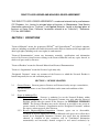
EPITORR User’s Guide Version 1.0 December 2006 RIGHT-TO-USE LICENSE AND NON-DISCLOSURE AGREEMENT THIS RIGHT-TO-USE LICENSE AGREEMENT is made and entered into by and between CIC Photonics, Inc., having its principal place of business in Albuquerque, New Mexico (hereinafter referred to as "Licensor"), and Applied Materials, having a principal place of business at Santa Clara, California, hereinafter referred to as "Licensee"). Reference: P.O. No. 4501245583 SECTION 1. DEFINITIONS "Licensed Material" means the proprietary SPGASTM and SpectraStreamTM and related computer software, including executable code and/or microcode on the delivered media and all copyrights and other legal rights (including trade secret rights) in such material. "Licensed Documentation" means any documents, materials, specifications and information received by Licensee from Licensor relating to the Licensed Material, and any copies thereof, in whole or in part, made by Licensee. "Licensed Products" means the Licensed Material and Licensed Documentation. "Licensee's Organization" means the Licensee legal entity only. “Designated Customer” means any customer of the Licensee to which the Licensed Product is loaned temporarily for test and evaluation purposes. SECTION 2. LICENSE GRANTED 2.1 Grant of License. Licensor grants to Licensee and Licensee hereby accepts a nonexclusive, non-transferable license to use Licensed Products on the terms and conditions of this Agreement. 2.2 Scope of Authorized Use. 2.2.1 Licensed Products. Licensee is authorized to use the Licensed Products within Licensee's Organization and at Designated Customer sites only when the Licensed Products remain under the control of the Licensee, for INTERNAL PURPOSES ONLY. The Licensed Products may not be delivered or provided to any person or persons outside of Licensee's Organization and its Designated Customers, without the express written approval of the Licensor. 2.2.2 Reverse Engineering/Non-Competition. Licensee agrees not to disassemble, decompile or reverse engineer the Licensed Materials and agrees not to allow these actions by its Designated Customers. Licensee also agrees that any information obtained in violation of this restriction will be Confidential Information automatically and irrevocably deemed assigned to and owned exclusively by 2 Licensor. Licensee further agrees not to distribute materials performing functions similar to those of the Licensed Materials without the prior written consent of Licensor. 2.3 Copyright. Licensor owns a copyright in the Licensed Products, as unpublished works or otherwise, and Licensee acknowledges same. 2.4 Assignment of License. Licensee's rights in and to the Licensed Software, as a result of this Agreement, may not be assigned, or otherwise transferred voluntarily, by operation of law, or otherwise, without Licensor's prior written consent. SECTION 3. TERM AND TERMINATION 3.1 The effective date of this Agreement shall be the date last signed below. This Agreement is for the life of the copyrights and trade secret rights to Licensed Products. Licensee may terminate this Agreement upon giving written notice to Licensor of its intent to terminate within thirty (30) days and by returning all copies of the Licensed Product in any form within said thirty (30) days. Licensor may terminate this License on ten (10) day's written notice for any material breach of this Agreement. 3.2 If a Maintenance Agreement has been purchased and is attached hereto, for a period of one (1) year from the effective date of said Maintenance Agreement or until this Agreement is terminated, whichever comes first, Licensor will send updates and modifications to the Licensee's specified point of contact. The Licensee point of contact is: Name: Address: Contact: Telephone: FAX: Maintenance Agreement ___ has ____ has not been purchased and ___ is ____ is not attached hereto. SECTION 4. PROPRIETARY INFORMATION 4.1 Restrictions on Disclosure. Licensee acknowledges that the Licensed Products contain proprietary and Confidential Information of Licensor. Licensee shall hold Confidential Information in confidence. Licensee shall not permit Confidential Information or any part thereof to be disclosed through sale, license, transfer or otherwise to any third person other than to employees of Licensee's Organization who must have access to Licensed Products in order to perform their work; provided, however, that Licensee shall have no obligation of confidentiality with respect to Information disclosed to Licensee by Licensor if: 3 (i) such information is, at the time of disclosure by Licensor to Licensee, in the public domain or such information thereafter becomes a part of the public domain without a breach of this Agreement by Licensee; or (ii) such information is known to Licensee at the time Licensor discloses it to Licensee; or (iii) such information is independently developed by Licensee; or (iv) such information is disclosed by Licensor to any third party, including the United States Government, without restriction as to further disclosure; or (v) such information is disclosed with the written approval of Licensor. Should Licensee determine that persons other than employees of Licensee require access to Confidential Information, such as employees of any subsidiary or parent company of Licensee, such disclosure may only be made with the prior written consent of Licensor. This Paragraph 4.1 shall survive the termination of this agreement. SECTION 5. LIMITED WARRANTY 5.1 The Licensed Products are warranted to perform substantially in accordance with the applicable manual provided with the Licensed Products for a period of one (1) year after the date of delivery of the Licensed Products. Licensor does not, however, warrant that the operation of the Licensed Products will meet Licensee requirements. 5.2 EXCEPT AS PROVIDED IN THIS LIMITED WARRANTY, LICENSOR MAKES AND LICENSEE RECEIVES NO WARRANTY, EXPRESS OR IMPLIED, INCLUDING BUT NOT LIMITED TO IMPLIED WARRANTIES OF MERCHANTABILITY AND/OR FITNESS FOR A PARTICULAR PURPOSE OR USE. 4 SECTION 6. LIMITATION OF REMEDIES 6.1 6.2 If Licensee reasonably determines that the Licensed Products do not perform as warranted, and notifies Licensor of the perceived defect during the aforesaid one (1) year warranty period, Licensor's entire liability and Licensee's exclusive remedy shall be for Licensor to: (i) Replace the Licensed Product, if determined necessary by Licensor, or, (ii) Use best efforts to respond within a reasonable time to telephone inquiries from Licensee with regard to problems with the Licensed Product. IN NO EVENT SHALL LICENSOR BE LIABLE TO LICENSEE FOR DAMAGES, INCLUDING ANY LOST PROFITS, LOST SAVINGS, LOST DATA, LOST OR DAMAGED LICENSED PRODUCTS, OR OTHER INCIDENTAL OR CONSEQUENTIAL DAMAGES ARISING OUT OF THE USE OR INABILITY TO USE THE LICENSED PRODUCTS OR FOR ANY CLAIM BY ANY OTHER PARTY. SECTION 7. GENERAL 7.1 Applicable Software. This Agreement applies to all purchases of the SPGAS and SpectraStream software products, past, present, and future, by Licensee, when purchased in conjunction with IRGAS Systems or separately as software. 7.2 Signature Authority. Licensor and Licensee acknowledge that the person signing this Agreement for each party has been properly authorized and empowered to enter into this Agreement. 7.3 Entire Agreement. This Agreement constitutes the entire agreement between the parties in connection with the subject matter hereof and supersedes all prior and contemporaneous agreements, understandings, negotiations, or discussions, whether oral or written, of the parties. 7.4 Applicable Law. This Agreement shall be construed and interpreted under the laws of the State of New Mexico and the parties agree that any lawsuit instituted based on this Agreement shall be brought in Albuquerque, New Mexico, in a court of proper jurisdiction. By: CIC Photonics, Inc. By: __________________ Signed:__________________________ Signed:__________________________ Name: Richard T. Meyer Name: Title: Title: Date: CEO & President Date: 5 FOREWORD Thank you for purchasing a CICP Photonics gas analysis system. We strive to build the best gas analyzers available and believe that you will be pleased with the performance of the IRGAS System. Should you have any difficulties at all please call (505) 343-1489 for technical assistance. We should be able to help you immediately. If you have any comments on this or any of our other products we would like to hear from you. We can be reached at the address, telephone numbers or e-mail address as given below. Thank you again for you business. Richard T. Meyer CEO & President 505-343-9500 Main 509-479-2980 Fax 505-343-1489 Technical Support CIC Photonics, Inc. 9000 Washington St. NE Albuquerque, NM 87113 [email protected] http://www.irgas.com COPYRIGHT © 2002 CIC Photonics, Inc. No information contained in this document may be reproduced in any form, in full or in part, without prior written permission from CIC Photonics, Inc. DISCLAIMER This document contains product specifications and performance statements that may be in conflict with other CIC Photonics published literature, such as product flyers and product catalogs. All specifications, product characteristics, and performance statements included in this document are given as suggestive specifications only. In case of conflict between product characteristics given in this document and specifications given in the official CIC Photonics Product Catalogs, the latter take precedence. CIC Photonics, Inc. reserves the right to make changes to the specifications of all equipment and software, and contents of this document, without obligation to notify any person or organization of such changes. Every effort has been made to insure that the information contained in this document is current and accurate. However, no guarantee is given or implied that the document is error-free or that the information is accurate. CIC Photonics, Inc. makes no representations or warranties with regard to the product and instructional and reference materials, including, but not limited to, all implied warranties of merchantability and fitness for a particular purpose. CIC Photonics, Inc. does not warrant, guarantee, or make any representations regarding the use, or the results of the use, of any software or written materials in terms of correctness, accuracy, reliability, currentness, or otherwise. CIC Photonics, Inc. shall not be liable for errors or omissions contained in its software or manuals, any interruptions of service, loss of business or anticipatory profits and/or for incidental or consequential damages in connection with the furnishing, performance or use of these materials even if CIC Photonics, Inc. has been advised of the possibility of such damages. All equipment, software, and manuals are sold as is. The entire risk as to the results and performance of the equipment and software is assumed by the user. TRADEMARKS Windows is a registered trademark of Microsoft Corporation. Workir is a registered trademark of ABB Bomem, Inc. GRAMS is a registered trademark of Thermo Galactic. IRGAS, SPGAS, and SpectraStream are registered trademarks of CIC Photonics, Inc. 6 WARRANTY ON PRODUCTS I. Since CIC Photonics builds its product to last, we warrant them that way. If you have a problem with our product, within the first year of ownership or within the specified warranty on a specific product, that is a result of a defect in workmanship or the wearing out of a component that should not wear out, we shall fix it. Products to be repaired under warranty are to be shipped back to our factory at user’s expense; after repair, product will be returned at CICP’s expense. II. Parts that normally wear out or are consumed or can be damaged in the normal operation of the product, such as fragile optical elements and seals (lenses, windows, crystals, mirrors, filters, C-seals, O-rings, etc.), are warranted against defect in manufacture only for a period of 30 days after original delivery to the purchaser. III. Technical assistance for either hardware or software that can be provided by telephone, fax, or email will be provided by CICP at no time charge to end users for the life of the products. IV. After the warranty period has expired, CICP offers service either on a time and materials basis or on an annual service and maintenance plan. 7 TABLE OF CONTENTS 1.0 INTRODUCTION………………………………………………………………………………………1 2.0 UNPACKING AND INSTALLATION…………………………………………………………………3 2.1 REMOVAL FROM SHIPPING CRATE AND PALLET……………………………….…...3 2.2 ELECTRICAL, ELECTRONIC, AND GAS CONNECTIONS……………………………...3 3.0 DESCRIPTION OF MAJOR COMPONENTS………………………………………………………….4 3.1 IRGAS SYSTEM OVERVIEW………………………………………………………….…...4 3.2 IRGAS SYSTEM OPERATIONAL MODES………………………………………………..6 3.3 BOMEM WORKIR FTIR SPECTROMETER…………………………………………….…6 3.4 4RUNNER LONG PATH GAS CELL……………………………………………………….6 3.5 TEMPERATURE CONTROLLER…………………………………………………………..7 3.6 CPU AND TOUCH SCREEN MONITOR…………………………………………………..7 3.7 PURGE AND SAMPLE GAS PLUMBING…………………………………………………8 3.8 SPGAS SYSTEM MANAGEMENT AND GAS QUANTIFICATION SOFTWARE……..12 3.9 SPECTRASTREAM FAST RESPONSE SOFTWARE MODULE………………………...12 3.10 ELECTRICAL SYSTEMS………………………………………………………………….12 4.0 SYSTEM START-UP OPERATIONS…………………………………………………………………14 4.1 PURGE GAS FLOW AND SYSTEM SWITCHES………………………...………………14 4.2 TEMPERATURE CONTROLLER AND GAS CELL HEATER.………………………….14 4.3 FTIR SPECTROMETER……………………………………………………………………14 4.4 COMPUTER SYSTEM…………………………………………………………………….14 4.5 SPGAS/SPECTRASTREAM SOFTWARE DISPLAYS…………………………………...16 4.6 SYSTEM TESTS………………………………..…………………....….………….………16 5.0 FULL SYSTEM OPERATIONAL PROCEDURES……………………………………………..…….21 5.1 GAS CELL PURGE………………………………………………………………..………..21 5.2 AUTOMATED DATA COLLECTION AND DISPLAY………………………………..…21 5.3 RECORDING, ARCHIVING, AND RECALLING OF COLLECTED DATA……..……..21 5.4 DOWNLOADING ARCHIVED DATA RECORDS…………………………….…………23 6.0 SYSTEM SHUTDOWN PROCEDURES……………………………………………….…………….23 6.1 TEMPORARY SHUTDOWN………………………………………………………………21 6.2 LONG TERM SHUTDOWN……………………………………………………………….24 6.3 MOISTURE PROTECTION………………………………………………………………..24 7.0 PACKING FOR SHIPMENT…………………………………………………..………..…………….24 8.0 SYSTEM DIAGNOSTICS AND TECHNICAL SUPPORT………………………….………..……..24 8.1 USER TESTS………………………………………………………………………..……...24 8.2 TELEPHONE AND EMAIL SUPPORT………………………………………….…….….24 8.3 TROUBLE-SHOOTING………………………………………………………………..…..25 8.3.1 GAS CELL DEGRADATION: MIRRORS, SEALS, WINDOWS……….……25 8.3.2 TEMPERATURE CONTROLLER AND HEATER…………………….……..25 8.3.3 FTIR SPECTROMETER……………………………………………….………25 8.3.4 CPU AND MONITOR………………………………………………………….25 8.3.5 NITROGEN PURIFIER AND GAS LINES……………………….….……….25 8.3.6 ELECTRICAL SYSTEM: FANS, FUSES……………………………………..26 8.3.7 VIBRATION AND SHOCK ISOLATORS……………………………………26 8.4 REMOVAL OF GAS CELL FOR WARRANTY REPAIR……………………………….26 9.0 APPENDICES…………………………………………………………………………………………27 8 LIST OF FIGURES FIGURE 1. FIGURE 2. FIGURE 3. FIGURE 4. FIGURE 5. FIGURE 6. FIGURE 7. FIGURE 8. FIGURE 9. FTIR SPECTROMETER AND PC INTERCONNECTION………………1 PROCESSES 1 AND 2 DIAGRAM………………………………….…….2 IRGAS-100T SYSTEM BLOCK DIAGRAM………………….….......…..5 START-UP SCREEN DISPLAY………………………………………....14 TYPICAL SCREEN DISPLAY OF CONCENTRATION VS TIME…..…16 MULTIPLE AND FAST SCAN CONCENTRATION DISPLAYS….…...17 SINGLE BEAM BACKGROUND RECORD………………………..........18 SINGLE BEAM SAMPLE RECORD………………………………….…..19 SINGLE BEAM MOISTURE BACKGROUND PEAK……………………21 1.0 Introduction The EPITORR Turnkey Gas Analysis System is a transportable version of CIC Photonics, Inc.’s product line of IRGAS – Integrated Real-Time Gas Analysis Solutions that was especially designed for applied materials. The EPITORR has been designed and developed to serve AMAT’s need for a high-sensitivity, fast-response time instrument. Typically this entails the measurement of gas compositions and impurity species within epitaxial reactors at the low ppb level within seconds. The EPITORR is designed for service with the numerous corrosive and toxic gases that are used in epitaxial reactors. The heart of the EPITORR is the all stainless steel 4RunnerTM long path gas cell; it provides the direct interface with the reactant gas flows. The 4Runner gas cell has a five-year track record of high performance in the analysis of all electrical gases in applications all over the world. The EPITORR is an industrial turnkey system that provides an automatic on-line monitoring analytical tool for the detection of impurities in corrosive and non-corrosive gases in real-time. The system is based on FTIR Spectroscopy and is controlled by SPGAS (Specialty Gas Analysis Software), which is a sophisticated software running on a personal computer. A system architecture was designed to provide the integration and control of the hardware elements, as well as the spectral analysis and chemometrics, to determine the concentration of impurities in gases. FTIR Spectroscopy offers the best characteristics to perform real-time detection of moisture and other impurities that may be present in epitaxial reactors. Since the infrared light detector is not in contact with the corrosive sample, it is not affected and the instrument can therefore be set for a continuous operation and scanning of the sample. The real-time gas analysis is performed through an FTIR Spectrometer, which contains a special gas sample compartment (gas cell) that is connected directly to a gas line that supplies the sample gas. Since the spectrometer is connected directly to a computer (see Figure 1), the spectrometer can be set to perform continuously an x number of scans of the sample gas and store this data as an interferogram. Every time an interferogram is completed, the computer retrieves this interferogram from the spectrometer and performs the quantitative gas analysis of the impurities. Gas Cell (A special designed gas sampling compartment) Personal Computer Purge Box (Used to interconnect the gas cell with the spectrometer inside the spectrometer's sample compartment) FTIR Spectrometer Figure 1 FTIR Spectrometer and Personal Computer Interconnection 1 Process 1 Process 2 System Initialization No, collect a new background spectra Is background spectra valid? Yes, continue sampling gases Interferogram Queue Wait until there is a stored interferogram in the queue and then retrieve it Set condition to collect a background spectra Calculate the absorption spectra of the sample based on the last spectrometer background reading Collect a background spectra and store it Perform chemometrics on data from the sampled gas to determine impurity concentrations Set and validate condition for sampling gases Retrieve data from spectrometer and store it Figure 2 Processes 1 and 2 block diagram The gas analysis process is divided in two main processes (Figure 2). One process is in charge of the data collection and the second process is in charge of the data processing. Process 1 controls the interaction between the spectrometer and the computer. Additionally, process 1 interacts with and synchronizes other sub-processes that set and control the sampling and the environmental conditions of the spectrometer. These sub-processes are in charge of controlling the gas handling system and the temperature controller if required. 2.0 Unpacking and Installation The EPITORR is a high performance instrument that includes an interferometer, laser, mirrors, windows, filters, high vacuum seals, and electronics. Hence, it must always be handled with a degree of care and precaution to prevent physical damage and optical misalignments. The EPITORR has been built into a Hardigg molded plastic enclosure of the type used in numerous transportable commercial and military instrumentation packages. A custom-designed vibration and shock mounting structure, which is bolted to the walls and floor of the Hardigg enclosure, provides isolation of the FTIR spectrometer and 4Runner gas cell subassembly; the internal CPU is embedded in the touch screen monitor. The enclosure has wheels on its bottom for easy movement within a lab or plant. 2 2.1 Removal from Shipping Crate and Pallet The EPITORR has been shipped inside a wooden crate mounted on a pallet. The top and side walls of the crate should be unscrewed from each other and removed to gain access to the instrument. All crate components should be stored for reuse and reshipping. The EPITORR has been affixed to a custom wooden pallet with tie-down straps over the sides of the enclosure. The contractors on the nylon straps should be released and the straps removed from the pallet. The straps, protective cardboard edge covers, and pallet (which has been designed for the unit with wheels) should be saved to use for later shipments of the system. Once the straps and cover are removed, the entire enclosure should be lifted off the pallet so that it can be set down on its wheels. The total weight of the EPITORR, without the pallet, is approximately 200 lbs; the enclosure has two handles on each side for lifting and rolling. Obviously it may take four persons to lift the unit off of the pallet. This should be done before opening the top lid of the enclosure, since it adds rigidity to the total physical enclosure. 2.2 Electrical, Electronic, and Gas Connections Once the EPITORR has been removed from the pallet and wheeled to its location for first use, then open the lid of the enclosure by disengaging the five locking clips and lifting the lid. The lid has one internal guy-wire, which allows the lid to be lifted back to a stable open position. The top panel is fitted with all the electrical, electronic, and gas connections and switches that are required for integrating the EPITORR with a user’s test station; all points of connection are labeled and include the following: Electrical power connector (120 volts, 6 amps): three-prong twist-lock male System switch (2 amps): flip switch Computer switch (1 amp): flip switch Heater switch (3 amps): flip switch Data terminal: Ethernet 10/100 female plug Floppy disk port (for transferring/archiving data) Nitrogen purge connector: male VCR fitting (to source of high purity N2 gas) Process gas “IN” connector: male VCR fitting (to source of process gas) Process gas “OUT” connector: male VCR fitting (to process gas exhaust) Also mounted on the top panel are: Two fans for exhausting cooling air from the internal volume Air filter (washable) for input of cooling air Touch screen monitor Gas cell temperature indicator/controller 3 3.0 Description of Major Components 3.1 EPITORR System Overview A System Block Diagram is provided in Figure 3. As will be seen, the use and operation of the EPITORR System are in general quite simple and easy to perform. EPITORR offers a robust design and works under Microsoft’s Windows XP professional Operating System. The minimum requirements of the system are as follow: SPGAS Minimum Hardware Requirements: • Pentium or AMD 133 Mhz • 64 MB Ram • One ISA slot free • 100 MB of free hard drive space Software Requirements: • Windows XP Professional 4 Figure 3. EPITORR System Block Diagram 5 3.2 EPITORR System Operational Modes The EPITORR system takes advantage of the built-in security features that Windows XP offers. These features allow one to set an account that will run the system in Operational Mode and another account for system Maintenance Mode. By logging-on in the Operational account, the EPITORR system starts automatically, and when the EPITORR system is closed, it automatically logs-off from the Operational account session. The Maintenance account for the EPITORR system allows access to all the EPITORR system configuration features. The EPITORR system does not start automatically every time the user logs-on in the Maintenance account. The Maintenance account provides access to the Windows XP standard desktop, from which the EPITORR system can be accessed or updated. The user can run the EPITORR System by double clicking on the IRGAS icon on the Window’s screen. 3.3 Bomem WorkIR FTIR Spectrometer The Bomem WorkIR FTIR spectrometer was chosen for the EPITORR because of its high quality patented interferometer, its total compactness and modest weight, and its industrial ruggedness. Technical features of the WorkIR are provided on the next page. The internal optics are KBr and the IR detector is a TE-Cooled InAs detector. The WorkIR internal compartment should be purged with ultra-dry nitrogen at all times. Electrical power is provided to the WorkIR when the “system” switch is turned on; it should be left “on” at all times to keep the spectrometer at a stable operating temperature and to reduce ambient moisture collection on the hydroscopic KBr optics; the cooling fans are continuously operating during this time. If the EPITORR is “stored” for any period of time, the WorkIR should first be purged and sealed with dry nitrogen. A complete Instruction Manual for the WorkIR is provided. 3.4 4Runner Long Path Gas Cell The 4Runner Long Path Gas Cell is an all stainless steel cell with stainless steel mirrors that have a custom coating structure of MgF2/Gold/Ti onto the stainless steel substrate. This configuration provides both high reflectivity in the infrared and chemical resistance to most all corrosive gases. The cell includes Chemraz O-rings are used in the following places: window mounts, objective mirrors, window seals, sight port cap, and the top and bottom seals. The IR beam input/output windows are IR Quartz for high IR transmission. The 4Runner gas cell is mounted on a purge box containing a two-position transfer mirror assembly. The transfer mirrors are moved in and out of the IR beam by means of an electronicallydriven motor and gear-drive. When the mirrors are aligned with the IR beam, the IR beam is transferred into and out-of the gas cell through the IR Quartz windows. When the mirrors are moved out of the IR beam, a wire-mesh filter moves into the beam to prevent saturation of the InAs detector. The cycling of the mirrors is controlled by the SPGAS/SpectraStream software program. The 4Runner is optically-coupled to the WorkIR using the optical housings provide with the spectrometer. This assembly of components is enclosed in a blue-anodized aluminum “Permeation Cover.” The permeation cover and its volume are flushed continuously with the purge nitrogen that escapes from the 4Runner purge box, which significantly reduces and/or eliminates air/moisture permeation through the Chemraz O-rings into the gas cell volume. 6 The WorkIR, 4Runner purge box, and optical housings (and the permeation cover) should be continuously purged with ultra-dry nitrogen at all times. The 4Runner gas cell volume should also be continuously purged when not being used to measure a process gas stream. Once the EPITORR System has been conditioned with ultra-dry nitrogen purging, the system can subsequently be closed-off from the sample and purge gas supply lines and transported to another in-plant location without significant deterioration of its moisture-dry status. Actual testing has shown that the system will maintain its dry condition for up to an hour or longer. In most cases, this is long enough to move the system from one process line to another and to reconnect the system for application. 3.5 Temperature Controller The 4Runner cell body is controlled with a 1/16 DIN Microprocessor-Based Auto-Tuning Controller. It drives a sheet heater with an imbedded Type K thermocouple that is mounted cylindrically on the cell body. The temperature setting is manually adjustable with touch switches on the face of the controller. The preset readout is in °C. Normal operating temperature range is ambient to 200°C. Warning: The Chemraz O-rings are only rated to 260°C for continuous use. Always operate the temperature controller in the “auto-tune mode” with a preset temperature maximum; that ensures that the temperature does not exceed the safe limit for the heater and the O-rings. A brief description of the operation of the controller is included in the 4Runner User’s Guide; and a complete User’s Manual is provided. 3.6 CPU and Touch screen Monitor The CPU is located inside the touch screen monitor. An electronic cable connects it to the touch screen monitor which is mounted on the top lid but can removed to the top panel for easier use. These units function in the same general manner as most PCs. The installed operating system is Microsoft XP professional. The CPU has been preloaded with CIC Photonics’ SPGASTM and SpectraStreamTM software and with HITRAN-generated gas calibration data for H2O, CO2, CH4, and HF. Both H2O and CO2 in ratio can be used to ascertain the presence of any air leakages into a process tool. 3.7 Purge and Sample Gas Plumbing VCR connections for the nitrogen purge gas (in) and for the process gas (in and out) are accessible at the back of the enclosure, on the left and right sides, respectively. Internally the purge gas line connects to a nitrogen purifier for moisture, which reduces the moisture purity of the ultradry nitrogen supply gas to the ppb level. This level of purity of the purge gas is required to ensure the best LOD for moisture in the process gases. 7 The nitrogen purifier is provided with a check valve at one end to protect it from air contamination when the nitrogen supply line is not connected; a manual shut-off valve is also located on the back side of the enclosure. The purifier under normal EPITORR usage will last for six to twelve months before regeneration is required; it can easily be changed out with a replacement unit. Warning: The nitrogen purifier should never be exposed to ambient air, since air moisture will contaminate the purifier. The process gas line is a direct stainless steel plumbing line from the top panel connection to the gas cell and back again without any valves, filters, or purifiers. The user must provide all mass flow controllers and other devices that may be required for handling the process gas. In addition, a separate connection to a house-supply of purified ultra-dry nitrogen is required for purging the 4Runner gas cell between process gas samples and for recording background spectra. 3.8 SPGAS System Management and Gas Quantification Software The complete version of CIC Photonics’ proprietary software, SPGAS, provides both system management of the hardware components and advanced gas quantification capability. The version installed in the EPITORR requires some manual operations of the hardware components—e.g. setting the temperature controller, opening/closing gas valves, etc. As stated above, the SPGAS software for the EPITORR has HITRAN-generated calibration data preinstalled for H2O, CH4, HF, and CO2. The installed reference calibrations for both species are 1 ppm; Beer’s Law is integrated to calculate all other concentrations for matching observed data with calculated data. 3.9 SpectraStream Fast Response Software Module SpectraStream is a proprietary (U.S. Patent Application Serial No. 09/731,550) add-on module to SPGAS. It provides a fast-response “early-warning” indication of sudden changes (within seconds) in the composition of the streaming gas that might arise from supply gas purity variations, system leakages, process tool failures, etc. Use of SpectraStream requires the motorized transfer mirror assembly described above. 3.10 Electrical Systems The electrical system for the EPITORR is a standard 120 volt, 6 amp system. There are three separate switched and fused circuits for the system, computer, and heater (for the gas cell). The heater is a stand-alone circuit with a 3-amp fuse; the computer is a subcircuit (1 amp fuse) off the main system fuse (2 amp). The system switch turns on and off all components except for the gas cell heater. A schematic of the electrical circuits is provided upon request. 8 4.0 System Start-up Operations 4.1 Purge Gas Flow and System Switches First start the flow of the ultra-dry nitrogen purge gas through the spectrometer and transfer mirror optics and separately through the gas cell; then turn on the system and computer switches. Purging of the system requires a total of 10 slpm; 5 slpm for the spectrometer and 5 slpm for the optical housing assembly. Internally, the EPITORR has two flow regulators, calibrated to provide 5 slpm each at 30 psig. Therefore, the system requires a constant supply of ultra-dry nitrogen at 30 psig at the purge inlet gas port. In addition and separately, the gas cell needs to be purged before and after any flow of process gases. This is best achieved by connecting the process gas line to the process reactor manifold so that either ultra-pure nitrogen or hydrogen can be applied as a purge gas. 4.2 Temperature Controller and Gas Cell Heater We recommend using 50°C as the on-going operational temperature for the gas cell during gas analyses and 125°C for the bakeout periods. The temperature controller has been preset at the factory at 60°C; it is manually adjustable to other temperatures. For the initial bakeout of the gas cell, we recommend 125°C with purge nitrogen for a 24hour start-up conditioning period. 4.3 FTIR Spectrometer The FTIR spectrometer is turned on when the system switch is turned on. It requires between three to six hours to stabilize for quantitative data collection; but it does start operating as soon as the system is turned on. The FTIR resolution has been preset at the factory for 2 cm-1, which is the resolution required for use with the SPGAS software; therefore, do not make any attempt to change the resolution. 4.4 Computer System The CPU and touch screen monitor become activated when the computer switch is turned on. The first screen to appear will look like Figure 4. Toward the middle upper right of the screen is a “Start/Stop” button, which will show “Start” initially because the computer has already activated the SPGAS software. Touching the button alternately “starts” and “stops” the operation of the spectrometer. At the lower right position are two displays: the upper is labeled “Show Spectra” with options for “Background,” “Sample,” and “Absorbance.” Below it is a display labeled “Collecting:” which indicates one of the following operations: “Background,” “Moving Mirrors,” or “sample.” Below it is a time line showing the “Time Left” for each of those three operations. The SPGAS software is causing the FTIR and transfer mirrors to cycle repeatedly through those three 9 Figure 4. Start-Up Screen Display 10 operations. With each completed cycle, the SPGAS performs a quantitative analysis of the collected data to generate the screen displays of spectra. At the “Show Spectra” display, one chooses which of the three options one wants displayed on the main portion of the screen. One can switch back and forth between the current background spectrum, the current sample spectrum, or the calculated absorbance record. At the top right of the screen, just below the “SpectraStream” logo is a scan bar, which shows on a 0 to 100% scale the percentage of the selected number of scans that have been performed by the FTIR. 4.5 SPGAS/SpectraStream Software Displays A typical SPGAS screen display is shown in Figure 5. It provides a graphical display of the concentrations of the selected gaseous species as a function of time. The gaseous species are those prescribed in advance to the factory for the inclusion of HITRAN calibration data. Also presented at the bottom of the screen is the “Concentration Log,” for the selected molecules. Two sets of concentration and standard error numbers are listed. The first set to the left are the concentration in ppb and its associated standard error from the long-term or multiple scan collection of data. The second set to the right presents the “FCT” (fast concentration tracker) results and associated standard error. The FCT numbers are generated by SpectraStream from single scan data collection to provide the fast-response, early-warning detection of changes in gas composition or impurity levels. The associated standard errors are greater because fewer data points are used in the calculations. These numbers are continuously updated as the SPGAS analyses proceeds. Above the graphical display are one or more buttons for the selected calibration gases. Touching one of these buttons brings up a display for that gas of both the multiple scan and the fast scan concentrations as a function of time. One such display is shown in Figure 6. The solid curve presents the multiple scan results and the dashed curve presents the single scan results. 4.6 System Tests There are two easy system tests that will reveal if the EPITORR is performing correctly. Both are based upon displays of single beam background data curves. One test determines if the movable mirrors in the optical transfer box actually move in and out of the IR beam as controlled by the SpectraStream module. The second test determines if the nitrogen purging of the spectrometer and optics has reduced the background moisture level to a minimum level. For the first test, switch to a background single beam record by touching the “Background” button under “Show Spectra.” This brings onto the screen a single beam record, Figure 7. Take note of or write down the maximum height of the single beam trace in arbitrary units. Then switch to the “Sample” single beam display and take note of its maximum height; see Figure 8. If the mirrors are moving “in” and “out” of the IR beam, the height of the “sample” single beam should be less than the height of the “Background” single beam. This is a consequence of the fact that in the “Sample” position, the IR beam is traversing a longer distance through the gas cell. 11 Figure 5. Typical Screen Display of Concentration vs Time 12 Figure 6. Multiple and Fast Scan Concentration Displays 13 Figure 7. Single Beam Background Record 14 Figure 8. Single Beam Sample Record 15 For the second test, display again the “Background” single beam record and look for the moisture absorption peak at 1653 cm-1. Magnify the display of that peak by touching the screen at that point and applying a downward left to right sweep to a scale size that is more easily readable. Estimate the effective magnitude of that peak from its peak up to a smoothed-curve position on the single beam. If the magnitude in arbitrary units is less than 0.05, adequate purging has occurred and one can proceed to sampling process gas for analysis; if not, then more nitrogen purging may be required. See Figure 9. 5.0 Full System Operational Procedures 5.1 Gas Cell Purge The gas cell should have been purged with ultra-pure nitrogen or hydrogen from the process tool manifold prior to and between the additions of the reactor treatment gases. 5.2 Automated Data Collection and Display As indicated in the start-up procedures, once the system is turned on, data collection begins immediately and continues to cycle between background data collection and sample data collection with a quantification analysis of absorbance performed for each complete cycle. The absorbance data are then converted to concentrations via the HITRAN gas calibrations and the resulting concentration values are displayed on the screen as a function of absolute time. The EPITORR is based upon the system operator being an active observer of the displays of gas concentrations to determine if departures from expected concentration levels occur. Such departures may occur due to changes in the quality of the supply gases, deterioration of inline gas purifiers, leaks in the gas lines or gas manifold components, degradation of seals in the process tool, alterations in the operating performance of the process tool, etc. The EPITORR is also dependent on the system operator keeping an independent log of operational changes with the process tool as a function of absolute time; this is necessary so that data archived by the EPITORR can be correlated at any later time with the performance of the process tool. 5.3 Recording, Archiving and Recalling of Collected Data Each cycle of background, sample, and absorbance data is automatically stored in a Grams SPC file format in archive folders on the hard disk of the CPU. The spectral records are stored in archive folders (D:\Irgas\Spectral Records) as the spectra are collected. “Spectral Records” Filename Convention: Background_”TimeStamp”.spc Sample_”TimeStamp”.spc Absorbance_”TimeStamp”.spc 16 Figure 9. Single Beam Moisture Background Peak 17 “TimeStamp” = “YY-MM-DD HH-MM-SS” A file is created about every 30 seconds. The “Spectra” files are stored inside a zip file in ½-hour increments to keep the file size manageable at < 1.4 mb: BackgroundTimeStamp.zip Sample.TimeStamp.zip Absorbance.TimeStamp.zip The “zip” files in turn are stored inside a folder with the creation date as their name: D:\IRGAS\Spectral Records\”Date”\ where “Date” = “YY-MM-DD” “Quantification Log” Filename Convention: Quan_”DateStamp”.Log “DateStamp” = “YY-MM-DD” The Quantification Log files are text files that are easily readable by software like MS Excel. A quantification is produced every 30 seconds and stored inside its Quantification Log file. One Quantification Log file is produced per day. These files are stored inside a folder with the year and month as their name: D:\IRGAS\Quantification Log\”YY-MM”\ The quantification calculations are stored in separate archive folders (D:\IRGAS\Quantification Log) in a similar manner. Files are retrieved by their date and hour identification. The file sizes have been defined for content size corresponding to a floppy disk, so that individual folders can be downloaded. 5.4 Downloading Archived Data Records It becomes necessary for the system operator to download archived data about every 30 days in order to free-up space on the hard disk. Use MS Windows standard procedures to copy files to floppy disks. A more efficient way is via the Ethernet 10/100 port for transfer of the data to the system operator’s in-house network; the latter likely requires engaging the assistance of the internal IT Department. 6.0 System Shutdown Procedures 6.1 Temporary Shutdown If the EPITORR is being shut down only temporarily and will be used again in the near term, then the system switch should be left on so that the FTIR spectrometer power remains on to 18 keep the internal temperature above ambient. The computer and heater switches may be turned off. It is also desirable to keep the nitrogen purge gas flowing through the spectrometer, transfer optics, and separately through the gas cell. 6.2 Long Term Shutdown Before turning off all power switches and terminating flow of purge nitrogen, the gas cell should be purged thoroughly with nitrogen using a purge, pump-out, bakeout procedure to rid the gas cell and process gas lines of all traces of the process gas; three cycles of purging and pumping with the gas cell temperature elevated is probably adequate. Allow the cell to cool to ambient temperature with purge nitrogen before stopping the flow and then cap the input and output lines with VCR caps and seals. 6.3 Moisture Protection The above procedures are designed partly to remove all adsorbed moisture from the gas lines and gas cell. Residual moisture in the presence of acid gases can be very destructive to the mirrors in the gas cell. 7.0 Packing for Shipment The EPITORR should be repacked for shipping forward in the same manner as it was received. That entails placing it back on the custom pallet so that the wheels are protected, replacing the top cardboard cover, tying it down with the four nylon straps, and reinstalling the panels of the wooden crate. 8.0 System Diagnostics and Technical Support 8.1 User Tests Repeat the tests described in Section 4.6 to ascertain if the system is performing correctly; call for technical support if there are any major departures from the prescribed test results. There is a built-in diagnostic to determine if the transfer mirrors in the gas cell purge box are functioning properly—that is, providing the movement in and out of the IR beam position. This diagnostic is provided at the following location: D:\IRGAS\PurgeBoxDiagnostic.exe 8.2 Telephone and Email Support Telephone technical support is available Monday through Friday, 8:30 am to 5:30 pm U.S. Mountain Time by calling 505-343-1489, 343-9520, or 343-9500; fax 509-479-2980. Inquiries may also be sent at anytime to: [email protected] with copy to [email protected]. 19 8.3 Trouble-shooting 8.3.1 Gas Cell Degradation: Mirrors, Seals, Windows The best way to track any degradation of the gas cell mirrors and windows is to keep a daily or weekly record of the energy throughput in a ratio measurement of the single beam magnitude for the IR beam through the empty cell (a “Sample” reading) compared to that for the IR beam bypassing the cell (a “Background” reading). When that ratio decreases to less than two-thirds of the value recorded for the cell when brand new, then there is some indication that either the windows are becoming coated or the mirror reflectivity is diminishing. At that point, fax or email your records to CIC Photonics for examination. Occasional testing of the gas cell and plumbing lines with a helium leak detector will provide assurances that the VCR fittings, and Chemraz O-rings are intact. Long term exposure of the Chemraz O-rings to high temperatures and acid gases can lead to their degradation. 8.3.2 Temperature Controller and Heater If there is indication that the gas cell is not being heated, first check the fuse on the temperature controller; a blown fuse may indicate a short in the wiring to the heater. Using an ohmmeter, then check the resistance across the leads to the heater; a good heater should read approximately 50 ohms. Do not overdrive the heating element by exceeding the temperature limit; the silicone rubber composition of the sheet heater will start to degrade at 300°C. 8.3.3 FTIR Spectrometer For proper operation, the spectrometer operating temperature must be kept at or below 30°C and should not exceed 40°C. In order to maintain a stable operating temperature, heat dissipators have been added to the spectrometer body and with the gas cell enclosure to transfer heat to the circulating air stream, which is provided by the two exhaust fans. The fans come on when the system switch is activated; if they do not come on, do not operate the spectrometer; shut the system down and call for technical support. 8.3.4 CPU and Monitor The computer uses a standard Windows XP professional Operating System; any IT Department should be able to troubleshoot it if necessary; or call CICP technical support. To shut down the CPU, first touch the “STOP” button on the screen; then click “OK” at the screen message and turn off the computer switch on the top panel. If the CPU takes too long to respond after you click “OK,” you may proceed to turn off the panel switch. If the Touch screen appears not to be functioning, look at the mouse symbol in the lower right bar on the screen; observe whether the RED indicator is on the left side of the mouse; if not touch the top left of the mouse to activate it. The mouse symbol operates like a physical mouse with left and right buttons, which you can toggle back and forth. 20 To use an on-screen keyboard, touch the keyboard symbol on the lower right bar. To use a physical keyboard, open the top panel and use a PS/2 connector to connect to the terminal on the internal CPU. If the system software has to be reinstalled, a CD Drive is required for connection to the CPU; call technical support for a copy of the software. 8.3.5 Nitrogen Purifier and Gas Lines The expected lifetime of the nitrogen purifier under normal continuous operation of the system is six to nine months, so long as it is not exposed to air. Indication that it may becoming saturated with moisture comes from a steady increase in the measured moisture content in the “Background” records. When this occurs to the extent that the background moisture is significantly interfering with quantitative measurements of moisture as an impurity in the process gases, the nitrogen purifier should be replaced. 8.3.6 Electrical System: Fans, Fuses, The system electrical circuitry is protected with a combination of three fuses (1, 2, and 3 amp). If any of these fail, a thorough check of the associated circuit should be conducted. 8.3.7 Vibration and Shock Isolators The internal instrument package, CPU, and nitrogen purifier are mounted within the system enclosure by means of a vibration and shock isolator assembly. The top panel may be removed to inspect the inside if there is any indication that some component may have come loose. Call for technical support if that occurs. 8.4 Removal of Gas Cell for Warranty Repair Should it become necessary to return the gas cell due to degradation of mirrors, windows, or seals, please call technical support for instructions. The gas cell can be removed and returned without having to return the entire IRGAS system. In brief what is involved is (1) flushing the cell well with purge nitrogen, (2) removing the blue anodized cover box which encloses the gas cell, (3) disconnecting the VCR fittings and capping them, (4) disconnecting the optical couplers at the purge box, and (5) lifting the cell off the spectrometer and out of the system enclosure. Then special packing and shipping procedures are to be followed. 21