1
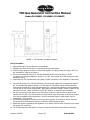
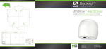
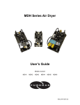
TOC Gas Generator Instruction Manual
Models P011008F1, P011008F4, P011008F5
Application
The TOC Gas Generator is designed for TOC Analyzers or any system requiring up to 500 cc/min of ultradry, CO2-free air.
System Requirements and Specifications
1.
2.
3.
4.
5.
6.
7.
Inlet Air Pressure: 100-125 PSIG Oil-Free Compressed Air
Minimum Inlet Air Flow: 1 liter/min @ 100 PSIG
Outlet Air Pressure: User Regulated from 0-80 PSIG.
Outlet Air Flow/Purity: Up to 500 cc/min at less than 1-ppm moisture and CO2.
Inlet Connection: 1/8” NPT (or 1/4” NPT Using Supplied Adapter)
Outlet Connection: 1/8” NPT (or 1/8” Tube Using Supplied Elbow)
Power Requirements: 100-240 Vac, 47-63 Hz, Single Phase, 400 mA
Inspection
Upon receipt of the TOC Gas Generator, please inspect the system to verify all parts are present and that
no shipping damage has occurred. If damaged, immediately file a claim with the shipping company.
The following parts should be included. If any are missing, please contact PUREGAS.
Item
1
2
3
4
5
6
7
8
9
10
11
12
Qty
1
1
1
1
1
3
1
1
1
1
1
1
Part Description
TOC Gas Generator Assembly
Filter- Coalescing, Inlet
Filter- Carbon, Inlet
Filter-Regulator, Outlet
Gauge- 1/8 NPT
1/8 NPT Hex Nipple
Power Supply w/ Plug Adapters
Adapter, 1/8 NPT X 1/4 FPT
Elbow- 1/8 NPT X 1/8 Tube
Mounting Template
Puregas Dryer/Adsorber Manual
TOC Instruction Manual
PUREGAS Part No.
N/A
P010616 (10F05ED)
P010976F1 (14F05Z)
P010618 (14E01B13FC)
PAT15093 (9692678)
PTM3
P011011F1
PMP25A1
P011007F1
P011020
P010535
P011021
Tools Required for Installation
The following tools will be required for installation:
1.
2.
3.
4.
5.
Wrenches: 7/16”, 9/16”, 11/16”
Adjustable Wrench
3/16” Hex Key
Drill and 3/8” Bit (if wall mounting is desired)
Pipe Thread Sealant or Teflon Thread Tape
Revised: 12/29/05
Page 1 of 3
P/N P011021
TOC Gas Generator Instruction Manual
Models P011008F1, P011008F4, P011008F5
FIGURE 1. TOC Generator Installation Diagram
Set-up Procedure
1. Apply thread seal on all pipe fittings to be assembled.
2. Assemble inlet filters as per Figure 1. Note flow direction and sequence.
3. Install pressure gauge to front port of outlet filter-regulator and plug to back port using a 3/16” hex
key. Assemble to outlet as per Figure 1.
4. Connect compressed air inlet line to TOC Gas Generator at filter inlet using either 1/8” NPT
connection or the supplied adapter to convert to ¼” NPT. Do not allow air to flow through unit until
energized (Step 6).
5. Pipe outlet from TOC Gas Generator using either 1/8 NPT connection or the supplied 1/8 Tube fitting.
6. Connect inlet power to the TOC Gas Generator using the power supply with the appropriate plug for
US- or European-style electrical outlets. For other types of connections, utilize the European plug
cord and cut the plug off to mount the appropriate plug. Note that the inlet power must be between
100-240 Vac at 47-63 Hertz (single phase). Note that a push-button ON/OFF switch is located on the
inlet side of the unit. When the switch is in the ‘OFF’ position, no outlet air will be available.
7. Run the unit with the on/off switch in the ‘ON’ position (pushed in) with the inlet air pressure set
between 100-125 PSI. The TOC Generator will cycle towers every 45 seconds, at which time a pulse
of air will be released inside the generator. The unit continually purges a small stream of air for
regeneration. This is normal.
8. Set the desired application pressure using the pressure regulator. First pull up to unlock, then turn
the knob until the desired outlet pressure is achieved. Relock by pushing down.
9. Outlet flow must be regulated by the application or by means of a flow meter such that no more than
500 cc/min flow is allowed.
10. The TOC Gas Generator will require 3-5 hours of initial run-time before best results are achieved.
Revised: 12/29/05
Page 2 of 3
P/N P011021
TOC Gas Generator Instruction Manual
Models P011008F1, P011008F4, P011008F5
Maintenance
At 6-month intervals, the inlet and outlet filter elements should be replaced. To replace filter elements,
de-energize the system and drain pressure to 0 PSIG. Unscrew the filter bowl (counterclockwise) to
access the filter element. Carefully unscrew the element (counterclockwise) and replace with new
element. It is recommended that the filter bowl be cleaned with a mild soap solution before installing it
back on the filter housing. After completing the element replacement, leak-test the filter with soapy water
prior to returning the unit to service.
•
•
•
P010617 - Replacement Element for P010616 Inlet Coalescing Filter (1 Required)
P010668 - Replacement Element for P010976F1 Inlet Carbon Filter (1 Required)
P010621 - Replacement Element for Outlet Filter-Regulator (1 Required)
These parts are available in one convenient maintenance kit: P011048F27 – TOC Maintenance Kit.
Be sure to schedule your next maintenance for 6 months and re-order the TOC Maintenance Kit.
For additional maintenance and replacement parts information, please see the supplied PUREGAS manual
(P010535).
Further Assistance
If further assistance is required, please contact:
PUREGAS, LLC
226A Commerce Street
Broomfield, Colorado 80020
Tel: 800.521.5351
Tel: 303.427.3700
Fax: 303.657.2205
[email protected]
www.puregas.com
Revised: 12/29/05
Page 3 of 3
P/N P011021