1
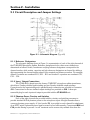
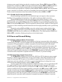
JT-MS-8N3
8 Channel 3 Way Microphone Splitter
with Phantom Power Circuitry
USER MANUAL
Revision 2.0
Table of Contents
Section 1 - Introduction . . . . . . . . . . . . . . . . . . . . . . . . . . . . . . . . . . . . . . . . . . 3
Section 2 - Installation
2.1 Circuit Description and Jumper Settings
Figure 2.1 - Schematic Diagram . . . . . . . . . . . . . . . . . . . . . . . . . . . . . . . .
2.1.1 Reference Designators . . . . . . . . . . . . . . . . . . . . . . . . . . . . . . . . . . . . . . . .
2.1.2 Input / Output Connections . . . . . . . . . . . . . . . . . . . . . . . . . . . . . . . . . . . . .
2.1.3 Phantom Power Circuitry and Switches . . . . . . . . . . . . . . . . . . . . . . . . . . . .
2.1.4 Ground Lift Circuitry and Switches . . . . . . . . . . . . . . . . . . . . . . . . . . . . . . .
2.2 Power and Ground Wiring
2.2.1 Chassis and Groundplane Connections . . . . . . . . . . . . . . . . . . . . . . . . . . . .
2.2.2 Phantom Power Supply Connections . . . . . . . . . . . . . . . . . . . . . . . . . . . . .
2.3 Input and Output Wiring
2.3.1 Input Wiring . . . . . . . . . . . . . . . . . . . . . . . . . . . . . . . . . . . . . . . . . . . . . . . . .
2.3.2 Output Wiring . . . . . . . . . . . . . . . . . . . . . . . . . . . . . . . . . . . . . . . . . . . . . . .
Figure 2.3 - Component Layout . . . . . . . . . . . . . . . . . . . . . . . . . . . . . . . .
2.4 Mounting
2.4.1 Rack Panel Mounting . . . . . . . . . . . . . . . . . . . . . . . . . . . . . . . . . . . . . . . . . .
2.4.2 Bulkhead Panel Mounting . . . . . . . . . . . . . . . . . . . . . . . . . . . . . . . . . . . . . .
Figure 2.4.1 - Rack Panel Drilling Guides . . . . . . . . . . . . . . . . . . . . .
4
4
4
4
5
5
5
6
6
6
7
7
7
Section 3 - Specifications and Physical Dimensions
3.1 Electrical Specifications
3.1.1 Frequency Response . . . . . . . . . . . . . . . . . . . . . . . . . . . . . . . . . . . . . . . . . .
3.1.2 Level Handling and Distortion . . . . . . . . . . . . . . . . . . . . . . . . . . . . . . . . . . .
3.1.3 Input Impedance . . . . . . . . . . . . . . . . . . . . . . . . . . . . . . . . . . . . . . . . . . . . .
3.1.4 Losses . . . . . . . . . . . . . . . . . . . . . . . . . . . . . . . . . . . . . . . . . . . . . . . . . . . . .
3.1.5 Common Mode Rejection Ratio . . . . . . . . . . . . . . . . . . . . . . . . . . . . . . . . . .
3.1.6 Phantom Power Requirements . . . . . . . . . . . . . . . . . . . . . . . . . . . . . . . . . .
3.2 Mechanical and Environmental Specifications
3.2.1 Dimensions . . . . . . . . . . . . . . . . . . . . . . . . . . . . . . . . . . . . . . . . . . . . . . . . .
Figure 3.2.1 - Mechanical Dimensions . . . . . . . . . . . . . . . . . . . . . . . . . . .
3.2.2 Weight . . . . . . . . . . . . . . . . . . . . . . . . . . . . . . . . . . . . . . . . . . . . . . . . . . . . .
3.2.3 Temperature Range and Humidity . . . . . . . . . . . . . . . . . . . . . . . . . . . . . . .
8
8
8
8
8
8
9
9
9
9
Section 4 - Warranty . . . . . . . . . . . . . . . . . . . . . . . . . . . . . . . . . . . . . . . . . . . . . . . . . . . . . 10
Printed in U.S.A. Copyright © 2001, Jensen Transformers, Inc.
2
Section 1 - Introduction
The Jensen JT-MS-8N3 provides 8 channels of extremely high quality 3 way microphone
splitting with 48 Volt phantom power individually selectable on each channel. This functionality is
provided in a compact 11.35"W x 4.75"H x 2.25"D package allowing 7 units (56 channels) to be
mounted vertically on a 7U size rack panel (see Figure 2.4.1). Excellent frequency response and
extremely low distortion are provided by the Jensen JT-MB-DPC microphone splitting transformers
that are used in the JT-MS-8N3.
Features:
•
8 Channels of Microphone Splitting/Isolation
•
Removable Screw Terminal I/O Connectors
•
Input, Direct Output and 2 Isolated Outputs per Channel
•
Individual Faraday Shields on All Inputs and Outputs for Maximum Noise Immunity
•
Ground Lift Switches Provided for Input and Each Output
•
Switchable Phantom Power Circuitry Provided on all Channels
•
Typical Distortion of only 0.001% at 1kHz
•
Extremely Wide 0.5Hz to 100kHz Bandwidth
•
Compact Form Factor Allows High Packaging Density
•
Rugged Steel Frame and 0.093" PCB Provide Added Durability
Printed in U.S.A. Copyright © 2001, Jensen Transformers, Inc.
3
Section 2 - Installation
2.1 Circuit Description and Jumper Settings
Figure 2.1 - Schematic Diagram (Typ of 8)
2.1.1 Reference Designators
The schematic diagram shown in Figure 1 is representative of each of the eight channels of
the JT-MS-8N3 Microphone Splitter. Reference designators for the other seven channels are
determined as follows: Switch, transformer and plug reference designators correspond to the
channel number, while resistor, capacitor and jack reference designators are formed by adding a
digit representing the channel number ahead of the nominal part reference number. For example,
channel 1 resistors are numbered R11, R12 ... R19 and channel 3 capacitors are numbered C31,
C32 ... C34.
2.1.2 Input / Output Connections
The JT-MS-8N3 is based upon the Jensen JT-MB-DPC microphone splitter transformer,
which has a Faraday shielded input winding and two Faraday shielded output windings.
Connections for the input winding and a parallel through connection are provided on connector
J11. Connections for the two isolated output windings are provided on J12. A three pin
removable plug for each input and output is provided with the JT-MS-8N3 unit.
2.1.3 Phantom Power Circuitry and Switches
Each of the eight channels are provided with the circuitry and switching necessary to
provide standard 48 Volt phantom power to the microphone input. All eight channels share a
common phantom power supply. A 3 pin header, P1, is provided on each channel for attachment
of an SPDT switch if phantom power must be turned on and off frequently. Components R18 and
C14 provide filtering to prevent “on-off” transients and to remove any residual noise from the
Printed in U.S.A. Copyright © 2001, Jensen Transformers, Inc.
4
phantom power supply before it reaches the microphone input. Resistor R15 discharges C14 to
ground if the connections to J13 are left open inadvertently. Resistors R16 and R17 provide the
phantom power to the microphone input and are precision matched to maintain balanced
common mode input impedances. Dipswitch positions S1-1, S1-2 and S1-3 allow the phantom
power connections to be either connected or completely disconnected from the microphone input.
Under normal circumstances, these three switches should be either all ON or all OFF.
2.1.4 Ground Lift Circuitry and Switches
Ground switching is provided for each individual input and output to allow maximum
flexibility in the grounding and termination of the splitter transformer shield connections.
Dipswitch S1-4 controls whether the microphone input shield is floating or connected to
ground through a low impedance network. Resistor R13 provides a low impedance to ground at
low frequencies and capacitor C13 provides a low impedance to ground at high frequencies when
S1-4 is in the default ON position. This low impedance network is used, instead of a hard ground
connection, to limit circulating currents between devices that might potentially create a ground loop
problem.
Dipswitch positions S1-5 and S1-6 connect the isolated output winding shields of the
microphone splitter transformer to ground through low impedance networks consisting of R11,
C12, R12 and C11 when the switches are in the ON position. The default position of S1-5 and
S1-6 is OFF, to simulate a floating microphone at the isolated output.
2.2 Power and Ground Wiring
2.2.1 Chassis and Groundplane Connections
The JT-MS-8N3 incorporates a groundplane on the top (component side) of the printed
circuit board to provide a very low impedance for the individual input and output ground dipswitch
connections. This groundplane is normally connected to the steel chassis plate by the default
jumper connection at P10. If alternate grounding connections are required for some reason, this
jumper may be moved to its alternate position, and the groundplane connection may be hardwired through the GND terminals on J91. Wire sizes between 14 and 26 gauge, either stranded or
solid, may be used to make connections to the JT-MS-8N3. Stranded wire should be used if
connections will be subjected to repeated movement or vibration, to prevent breakage.
2.2.2 Phantom Power Supply Connections
The JT-MS-8N3 is designed to be used with a 48 Volt to 52 Volt phantom power supply.
Normally, a 48 Volt supply will work fine. In some cases though, when using microphones that
require the maximum 48 Volt power to be available for proper operation, the phantom power
supply may need to be adjusted to 52 Volts to overcome the slight drop in voltage that occurs
across the transient filtering network consists of R18 and C14.
A power supply with a floating (transformer isolated) secondary, such as a typical linear ACDC supply, should be used to prevent creating any inadvertent paths to ground. The positive
terminal of the power supply should be connected to the 48+ terminal of J91. The negative, or
common, terminal of the power supply should be connected to the 48C terminal of J91. Parallel
through connections are provided on J91 to facilitate “daisy-chaining” of the phantom power
connections when utilizing multiple JT-MS-8N3 assemblies. Wire sizes between 14 and 26 gauge,
either stranded or solid, may be used to make connections to the JT-MS-8N3. Stranded wire
should be used if connections will be subjected to repeated movement or vibration, to prevent
Printed in U.S.A. Copyright © 2001, Jensen Transformers, Inc.
5
breakage.
Under normal circumstances, the low side of the phantom power supply, 48C, is connected
directly to the groundplane, GND, through the jumper at P9. If this needs to be changed for some
reason, the jumper may be moved to its alternate position, and the phantom power supply
common, 48C on J91, may connected to some other reference point.
2.3 Input and Output Wiring
In order to avoid wiring confusion, the HI, LO and SHIELD connections are arranged in the same
order for each of the INPUT, THRU, OUTPUT 1 and OUTPUT 2 connector positions.
2.3.1 Input Wiring
INPUT and THRU connections are provided on pins 1 through 6 of J11:
INPUT HI, LO and Shield connections are on pins 1, 2 and 3 respectively.
THRU HI, LO and Shield connections are on pins 4, 5 and 6 respectively.
2.3.2 Output Wiring
Isolated Output connections are provided on pins 1 through 6 of J12.
OUTPUT 1 HI, LO and Shield connections are on pins 1, 2 and 3 respectively.
OUTPUT 2 HI, LO and Shield connections are on pins 4, 5 and 6 respectively.
Wire sizes between 14 and 26 gauge, either stranded or solid, may be used to make
connections to the JT-MS-8N3. Stranded wire should be used if connections will be subjected to
repeated movement or vibration, to prevent breakage.
Figure 2.3 - Component Layout
Printed in U.S.A. Copyright © 2001, Jensen Transformers, Inc.
6
2.4 Mounting
The JT-MS-8N3 is equipped with three sets of mounting holes to provide the flexibility
required to accommodate many different types of installation requirements. It may be mounted
either vertically or horizontally on a 19" rack type panel or it may be secured to a wall or bulkhead.
2.4.1 Rack Panel Mounting
Four 8-32 PEM type fasteners are provided along the bottom mounting flange of the JTMS-8N3 for mounting to standard 19" rack panels. A single JT-MS-8N3 unit may be mounted
horizontally to a 2U rack panel. Up to seven JT-MS-8N3 units may be mounted vertically to a 7U
rack panel. See Figure 2.4.1 for 2U and 7U rack panel drilling guides.
2.4.2 Bulkhead Panel Mounting
Four 0.172" diameter mounting holes are provided along the bottom mounting flange and
along the top edge of the JT-MS-8N3 for mounting the unit with the printed circuit board either
parallel to or perpendicular to a bulkhead or wall. If the unit is mounted with the printed circuit
board parallel to the bulkhead or wall, four right angle mounting brackets may be also used to
attach the bottom flange to the wall for additional rigidity.
Figure 4.2.1 - Rack Panel Drilling Guides
Printed in U.S.A. Copyright © 2001, Jensen Transformers, Inc.
7
Section 3 - Specifications
3.1 Electrical Specifications
3.1.1 Frequency Response (150 Ohm source, 1500 Ohm preamp load at each isolated output)
High Frequency -3dB Cutoff
Isolated Output 1 . . . . . . . . . . . . . . . . . . . . . . . . . . . . . . . . . . . . . . . . . . . . . 108kHz
Isolated Output 2 . . . . . . . . . . . . . . . . . . . . . . . . . . . . . . . . . . . . . . . . . . . . . 130kHz
Low Frequency -3dB Cutoff
Isolated Output 1 . . . . . . . . . . . . . . . . . . . . . . . . . . . . . . . . . . . . . . . . . . . . . . . 0.4Hz
Isolated Output 2 . . . . . . . . . . . . . . . . . . . . . . . . . . . . . . . . . . . . . . . . . . . . . . . 0.4Hz
20Hz / 20kHz Response re: 1kHz
Isolated Output 1 . . . . . . . . . . . . . . . . . . . . . . . . . . . . . . . . . . . . . -0.10dB / -0.10dB
Isolated Output 2 . . . . . . . . . . . . . . . . . . . . . . . . . . . . . . . . . . . . . -0.10dB / -0.04dB
3.1.2 Level Handling and Distortion
Maximum 20Hz Input Level at 1% THD . . . . . . . . . . . . . . . . . . . . . . . . . . +2dBu (0.975V)
Maximum 50Hz Input Level at 1% THD . . . . . . . . . . . . . . . . . . . . . . . . . +10dBu (2.449V)
Total Harmonic Distortion at 20Hz and -20dBu . . . . . . . . . . . . . . . . . . . . . . . . . . . . 0.05%
Total Harmonic Distortion at 1kHz and -20dBu . . . . . . . . . . . . . . . . . . . . . . . . . . . . 0.001%
3.1.3 Input Impedance
Input Impedance with no preamp loads . . . . . . . . . . . . . . . . . . . . . . . . . . . . . . . 1.52k Ohms
Input Impedance with 1 1500 Ohm preamp load . . . . . . . . . . . . . . . . . . . . . . . . 818 Ohms
Input Impedance with 2 1500 Ohm preamp loads . . . . . . . . . . . . . . . . . . . . . . . . 569 Ohms
3.1.4 Losses
Output with 1500 Ohm preamp load referenced to Input
Isolated Output 1 . . . . . . . . . . . . . . . . . . . . . . . . . . . . . . . . . . . . . . . . . . . . . -1.32dB
Isolated Output 2 . . . . . . . . . . . . . . . . . . . . . . . . . . . . . . . . . . . . . . . . . . . . . -1.25dB
3.1.5 Common Mode Rejection Ratio
60Hz CMRR
Isolated Output 1 . . . . . . . . . . . . . . . . . . . . . . . . . . . . . . . . . . . . . . . . . . . . . . 120dB
Isolated Output 2 . . . . . . . . . . . . . . . . . . . . . . . . . . . . . . . . . . . . . . . . . . . . . . 110dB
3kHz CMRR
Isolated Output 1 . . . . . . . . . . . . . . . . . . . . . . . . . . . . . . . . . . . . . . . . . . . . . . . 90dB
Isolated Output 2 . . . . . . . . . . . . . . . . . . . . . . . . . . . . . . . . . . . . . . . . . . . . . . . 80dB
3.1.6 Phantom Power Requirements
Nominal Input Voltage . . . . . . . . . . . . . . . . . . . . . . . . . . . . . . . . . . . . . . . . . . . . . . . 48 Volts
Maximum Input Voltage . . . . . . . . . . . . . . . . . . . . . . . . . . . . . . . . . . . . . . . . . . . . . . 56 Volts
Nominal Phantom Current (Total of 8 Channels - 48 Volts) . . . . . . . . . . . . . . 53 milliamps
Maximum Phantom Power Current (All 8 Channels Shorted - 56 Volts) . . . . 125 milliamps
Printed in U.S.A. Copyright © 2001, Jensen Transformers, Inc.
8
3.2 Mechanical and Environmental Specifications
3.2.1 Dimensions
Length . . . . . . . . . . . . . . . . . . . . . . . . . . . . . . . . . . . . . . . . . . . . . 11.35 Inches (288.3 mm)
Width . . . . . . . . . . . . . . . . . . . . . . . . . . . . . . . . . . . . . . . . . . . . . . . 4.75 Inches (120.6 mm)
Height . . . . . . . . . . . . . . . . . . . . . . . . . . . . . . . . . . . . . . . . . . . . . . . 2.25 Inches (57.1 mm)
3.2.2 Weight
Net Weight (Including all 34 Plug-in Connectors and Mtg. Screws) . . . . . 3.75 lb. (1.70 kg.)
Shipping Weight . . . . . . . . . . . . . . . . . . . . . . . . . . . . . . . . . . . . . . . . . . . . . 4.5 lb. (2.1 kg.)
3.2.3 Temperature Range and Humidity
Operation or Storage Temperature . . . . . . . 32E to 158E Fahrenheit (0E to 70ECentigrade)
Humidity . . . . . . . . . . . . . . . . . . . . . . . . . . . . . . . . . . . . . . . . 10% to 90% non-condensing
Figure 3.2.1 - Mechanical Dimensions
Printed in U.S.A. Copyright © 2001, Jensen Transformers, Inc.
9
Section 4 - Warranty
For a period of 1 YEAR after purchase, Jensen Transformers, Inc. will, free of charge, repair
or replace any part of an ISO-MAX® product that fails due to defective materials or workmanship.
For a period of 20 YEARS after purchase, Jensen Transformers, Inc. will, free of charge,
repair or replace any Jensen OEM transformer or any Jensen transformer contained in an ISOMAX® product that fails due to defective materials or workmanship.
Both limited warranties are subject to the following limitations:
1) Defects that are, in the sole judgement of Jensen, the result of accident, misuse, abuse, neglect,
mishandling, misapplication, faulty installation, unauthorized repair, modification, or acts of God
will not be covered by this warranty.
2) In the absence of proof of date of purchase, the date of manufacture (as determined from lot
numbers of internal parts and the records of Jensen Transformers, Inc.) shall be used in its place.
3) There are no express warranties except as listed above.
4) JENSEN TRANSFORMERS, INC. SHALL NOT BE LIABLE FOR INCIDENTAL OR
CONSEQUENTIAL DAMAGES RESULTING FROM THE USE OF THIS PRODUCT OR ARISING
OUT OF THE BREACH OF THIS WARRANTY. Duration of implied warranties, if any, is limited
to 12 months. If a problem develops with this product during the warranty period, call or write us
before attempting any repair. We can help you identify specific problems, and possibly solve the
problem, before the unit is returned to us for repair or replacement. In any case, DO NOT
RETURN THE UNIT WITHOUT AUTHORIZATION and instructions from us. Jensen cannot be
responsible for damage due to shipping or improper packaging.
Limitations of Liability
The information provided by Jensen about its products been checked and is believed to be
accurate; however, no responsibility is assumed by Jensen for its use nor for any infringements of
patents which may result from its use. No license is granted by implication or otherwise under any
patent or patent right of Jensen Transformers, Inc.
JENSEN PRODUCTS ARE NOT AUTHORIZED FOR USE AS CRITICAL
COMPONENTS IN LIFE SUPPORT DEVICES OR SYSTEMS, OR IN ANY
APPLICATION WHERE THEIR FAILURE COULD CAUSE INJURY OR DEATH.
Jensen reserves the right to make changes without further notice to any of its products.
Jensen makes no warranty, representation or guarantee regarding the suitability of any of its
products for any particular purpose, nor does Jensen assume any liability arising out of the
application or use of any product or circuit, and specifically disclaims any and all liability, including
without limitation consequential or incidental damages.
Printed in U.S.A. Copyright © 2001, Jensen Transformers, Inc.
10