1
breakage.
Under normal circumstances, the low side of the phantom power supply, 48C, is connected
directly to the groundplane, GND, through the jumper at P9. If this needs to be changed for some
reason, the jumper may be moved to its alternate position, and the phantom power supply
common, 48C on J91, may connected to some other reference point.
2.3 Input and Output Wiring
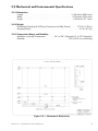
In order to avoid wiring confusion, the HI, LO and SHIELD connections are arranged in the same
order for each of the INPUT, THRU, OUTPUT 1 and OUTPUT 2 connector positions.
2.3.1 Input Wiring
INPUT and THRU connections are provided on pins 1 through 6 of J11:
INPUT HI, LO and Shield connections are on pins 1, 2 and 3 respectively.
THRU HI, LO and Shield connections are on pins 4, 5 and 6 respectively.
2.3.2 Output Wiring
Isolated Output connections are provided on pins 1 through 6 of J12.
OUTPUT 1 HI, LO and Shield connections are on pins 1, 2 and 3 respectively.
OUTPUT 2 HI, LO and Shield connections are on pins 4, 5 and 6 respectively.
Wire sizes between 14 and 26 gauge, either stranded or solid, may be used to make
connections to the JT-MS-8N3. Stranded wire should be used if connections will be subjected to
repeated movement or vibration, to prevent breakage.
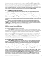
Figure 2.3 - Component Layout
Printed in U.S.A. Copyright © 2001, Jensen Transformers, Inc.
6