1
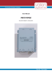
User Manual for the Family of
Acoustic Emission Signal Conditioners
ASCO-PXx
Contents:
Applications ............................................................................................................................................. 2
1
2
Blockdiagram ........................................................................................................................................... 2
3
Sensors ..................................................................................................................................................... 2
4
ASCO-P Derivatives................................................................................................................................. 3
4.1 Overview on all ASCO-P Derivatives ..................................................................................................3
4.1.1 ASCO-Px ............................................................................................................................... 3
4.1.2 ASCO-PNx, PHx.................................................................................................................... 3
4.1.3 ASCO-PHx ............................................................................................................................ 3
4.2 Properties of ASCO-P Derivatives (typical) ........................................................................................3
4.3 Property „APK-ASL“ ............................................................................................................................3
4.4 Revisions.............................................................................................................................................4
4.5 Special versions ..................................................................................................................................4
5
Specifications of ASCO-Pxx ................................................................................................................... 5
5.1 AE-Preamplifier (sensor-connector):...................................................................................................5
5.2 Threshold-Input: ..................................................................................................................................5
5.3 Filter Output:........................................................................................................................................5
5.4 APK-Output: (Peak-Amplitude) ...........................................................................................................5
5.5 ASL-Output: (Average Signal Level) ...................................................................................................5
5.6 Reset Input: .........................................................................................................................................5
5.7 Opto-Output:........................................................................................................................................5
5.8 Supply Voltage: ...................................................................................................................................5
5.9 Connectors (ASCO-side): ...................................................................................................................5
5.10 Housing: (aluminium profile) ...............................................................................................................5
5.11 Environment conditions:......................................................................................................................5
5.12 Accessories available:.........................................................................................................................5
6
I/O-Connector Pinout............................................................................................................................... 6
7
Modification of the Peak-Stretcher-Time............................................................................................... 6
8
Modification of the Pulse Width (Opto-Coupling-Output) ................................................................... 6
9
Adjustments (not recommended without being trained)..................................................................... 7
10 Component Location on the Printed Circuit Board.............................................................................. 7
10.1 Top side: (R251, R301 not inserted. Parallel to R25, R30 for easy modification) ..............................7
10.2 Bottom side: ........................................................................................................................................7
11 Details on ASCO-P Results..................................................................................................................... 8
11.1 APK Acoustic Peak .............................................................................................................................8
11.2 ASL Average Signal Level ..................................................................................................................9
11.2.1 How the ASL is obtained ....................................................................................................... 9
12 How to start ............................................................................................................................................ 10
12.1 General..............................................................................................................................................10
12.2 Connections ......................................................................................................................................10
12.3 Sensor-Coupling ...............................................................................................................................10
12.4 Testing Environment and Noise ........................................................................................................11
12.5 First Analysis .....................................................................................................................................11
13 Regulations concerning redemption and disposal of ASCO-P ........................................................ 11
Tel: +49 8178 9674-400
Fax: +49 8178 9674-444
file: ASCOmanE0803 page 1/12
Copyright © 2008, Vallen Systeme GmbH
Schäftlarner Weg 26a, 82057 Icking, (Munich), Germany
email: [email protected]
http://www.vallen.de
Manual ASCO-P
1
Applications
The ASCO-P (Acoustic Signal Conditioner with Peak Detector) lets you detect damage mechanisms, such
as crack formation, crack growth, fiber breakage, delamination, debonding of surfaces and others, as they
happen! This works with all brittle materials, e.g. fiber reinforced plastics, composites, ceramics, metals and
many more. In addition, the ASCO-P can detect and monitor leaks, partial discharge, particle impact, flow
turbulences, friction, corrosion and more.
The ASCO-P conditions the AE signal such that it can be recorded and evaluated by using a low-cost PC
plug-in data acquisition card and a minimum of software that shows voltage over time. With ASCO-P the
integration of AE measurements into an industrial application becomes straight forward and very
cost effective. The ASCO-P forms a very useful completion of your mechanical testing machine (tensile,
bending, scratch tests etc.) because it provides valuable information on the damage process in your sample
with very little effort.
2
Blockdiagram
The AE signal (delivered by a piezo-electrical AE-sensor) is fed-in over a BNC-connector and amplified by a
low noise preamplifier. A filter module rejects undesired frequency components. The high frequency signal is
rectified and the logarithm is obtained. This signal is smoothened by a low pass filter and presented at the
Output ASL (average signal level). In parallel, the logarithm signal is processed by a peak-stretcher which
holds even very short peak values for a defined time period and presents it at the Output APK (AE peak
amplitude). The log signal is compared against a threshold fed-in as analogue voltage (e.g. the analogue
output of a PC card). When the signal exceeds the selected threshold a pulse is generated, fed over an
optocoupler and presented at the pins Optocoupler+ and Optocoupler-. Depending on the application this
can trigger e.g. an alarm, or an image record, an event counter, or a more detailed analysis of the incoming
data.
3
Sensors
For the detection of rapid changes in the material, such as crack formation and growth, fracture, partial
discharge, etc., we recommend our sensor VS150-M which has the peak sensitivity at 150kHz. For the
detection of leak or friction in the range 25 to 80kHz, we recommend the VS30-V. For high frequencies up to
1.3MHz, e.g. from thin fiber reinforced materials or paper the VS700-D is well suited.
In order to meet special requirements, for instance high temperatures, different sensors have to be chosen.
Sensor and the model of the ASCO-P family have to be chosen according to the frequency range of interest.
Tel: +49 8178 9674-400
Fax: +49 8178 9674-444
file: ASCOmanE0803 page 2/12
Copyright © 2008, Vallen Systeme GmbH
Schäftlarner Weg 26a, 82057 Icking, (Munich), Germany
email: [email protected]
http://www.vallen.de
Manual ASCO-P
4
ASCO-P Derivatives
4.1
Overview on all ASCO-P Derivatives
4.1.1
ASCO-Px
The Suffix ’x’ is replaced by a number which specifies together with P/PN or PH a frequency range
according to table 4.2. ASCO-Px is identical to the former ASCO-P with filter module FMx.
4.1.2
ASCO-PNx, PHx
The derivatives ASCO-PNx und PHx are successors of the ASCO-Px. They differ from ASCO-Px with
respect to the low-pass at the ASL-Output. For the ASCO-Px this low-pass is 2-pole 50Hz, for ASCO-PNx
and –PHx this low pass is 1-pole 86Hz. The 1-pole filter allows the determination of an energy-proportional
result for each detection interval. An optimum is reached for 5000 Scans/s. For such a high sample rate we
recommend to enable the short PST (Peak Stretching Time) by removing jumper JP2. This also allows to
resolve hit rates up to 1000/s and more.
4.1.3
ASCO-PHx
With the ASCO-PHx the usable frequency range is 90 to 1300kHz. In addition to the higher frequency range
this derivative realizes a considerably shorter rise time of the APK-Output (7µs instead of 25µs). This implies
an increased electric noise. For higher frequencies we recommend higher sampling rates and also the
shorter PST.
4.2
Properties of ASCO-P Derivatives (typical)
frequency
APKASL
APK
ASL
APK
noise
noise
range
noise
rise time
noise
Derivative
[kHz]
50R [V]
ASL-filter
50R [V]
50R [dB]
[µs]
50R [dB]
ASCO-P1
90-295
25µs
0,654
0,948
16,4
23,7
2-pole 50Hz
ASCO-P2
20-84
25µs
0,428
0,591
10,7
14,8
2-pole 50Hz
ASCO-P3
240-575
25µs
0,954
1,233
23,9
30,8
2-pole 50Hz
ASCO-P4
195-375
25µs
0,858
1,163
21,5
29,1
2-pole 50Hz
90-295
25µs
0,654
0,948
16,4
23,7
1-pole 86Hz
ASCO-PN1
20-84
25µs
0,428
0,591
10,7
14,8
1-pole 86Hz
ASCO-PN2
ASCO-PN3
240-575
25µs
0,954
1,233
23,9
30,8
1-pole 86Hz
ASCO-PN4
195-375
25µs
0,858
1,163
21,5
29,1
1-pole 86Hz
ASCO-PH1
90-295
7µs
0,813
1,125
20,3
28,1
1-pole 86Hz
240-710
7µs
0,935
1,347
23,4
33,7
1-pole 86Hz
ASCO-PH3
ASCO-PH4
190-385
7µs
0,920
1,323
23,0
33,1
1-pole 86Hz
90-1300
7µs
0,971
1,243
24,3
31,1
1-pole 86Hz
ASCO-PH5
ASCO-PH6
240-1200
7µs
0,958
1,330
24,0
33,3
1-pole 86Hz
The bold printed derivatives PN1, PN2, PH3 and PH5 are preferred on stock for short delivery time.
4.3
Property „APK-ASL“
APK and ASL are derived from the same logarithmic output, but APK represents the peak amplitude and
ASL the average. The average is gained by a smoothing low-pass. This causes a difference between the
levels of APK (e.g. of a sineburst) and ASL (e.g. a continuous sinewave) which increases with decreasing
frequency. The following table shows this difference at 2 frequencies for each ASCO-P derivative: at the socalled testing frequency and half the testing frequency. Each ASCO-P derivative is adjusted such that the
APK Output at the testing frequency is optimized for lowest deviation from the input (burst) signal. The
testing protocol coming with the ASCO-P shows (among others) the frequency dependence of the APK
output and the difference „APK-ASL“ (example below). Negative values for APK-ASL appear, if the APK
risetime hinders the APK level to reach the peak level. For the measurement of short bursts of frequencies
above 300kHz we recommend the derivatives ASCO-PHx.
Tel: +49 8178 9674-400
Fax: +49 8178 9674-444
file: ASCOmanE0803 page 3/12
Copyright © 2008, Vallen Systeme GmbH
Schäftlarner Weg 26a, 82057 Icking, (Munich), Germany
email: [email protected]
http://www.vallen.de
Manual ASCO-P
Derivative
ASCO-P1
ASCO-P2
ASCO-P3
ASCO-P4
ASCO-PN1
ASCO-PN2
ASCO-PN3
ASCO-PN4
ASCO-PH1
ASCO-PH3
ASCO-PH4
ASCO-PH5
ASCO-PH6
Frequency range
[kHz]
90-295
20-84
240-575
195-375
90-295
20-84
240-575
195-375
90-295
240-710
190-385
90-1300
240-1200
Test frequency
[kHz]
200
60
500
300
200
60
500
300
200
500
300
500
500
APK-ASL [dB]
at test frequency
0dB
1,3dB
-1,2
0
0dB
1,3dB
-1,2
0
3
0,6
1,8
0,6
0,5
APK-ASL [dB]
at 0,5*test frequency
0,7dB
2,7dB
-0,3
0,3
0,7dB
2,7dB
-0,3
0,3
4,6
2,1
3,4
2,2
2,5
Example for frequency dependence of APK and APK-ASL (ASCO-PN4), as shown in the testing protocol:
dB
95
APK[dB]
APK-ASL[dB]
dB
1,0
90
0,5
85
0,0
80
-0,5
75
-1,0
70
-1,5
65
-2,0
60
-2,5
10000
10
100
1000
kHz
4.4
Revisions
ASCO-P-R1:
initial standard version
ASCO-P-R2:
developed for option O1, R2 became standard for ASCO-P delivered after July 2004
- Opto output: driving capability increased from 2.5mA to 10mA,
- Internal pullup-resistor at Pin 2 (Sub D 15) reduced from 2K2 auf 680R
ASCO-P-R3..R5 not relevant
ASCO-Px-R6: Modification for reduced noise especially at low frequencies, and change of adjusting
procedure and testing protocol (automatic)
ASCO-PNx-R0, ASCO-PHx-R0: like ASCO-P-R6, ASL Output filters changed to 1-pole, 86Hz.
4.5
Special versions
ASCO-P-O1: (available since February 2004):
- Like ASCO-P1-R2, from 12/2005 like ASCO-P1-R6
- Supply voltage: 22-26V instead of 7-15V, feed in this higher voltage ONLY at the JACK PLUG,
NOT at the SubD15-connector.
- Peak-Stretching Time: 1.5ms
- Opto Output Pulse Width: 1ms
Tel: +49 8178 9674-400
Fax: +49 8178 9674-444
file: ASCOmanE0803 page 4/12
Copyright © 2008, Vallen Systeme GmbH
Schäftlarner Weg 26a, 82057 Icking, (Munich), Germany
email: [email protected]
http://www.vallen.de
Manual ASCO-P
5
Specifications of ASCO-Pxx
Derivative overview in paragraph 4.
5.1
AE-Preamplifier (sensor-connector):
Input impedance:
Meas.range:
Gain:
Noise (Inp.50R):
Freq. range [kHz]:
Filter roll-off:
Charakteristic:
5.2
>10MOhm parallel 10pF
±100mVPK = 100dBAE
20dB
P1, PN1:24dBAE
P2, PN2: 16dBAE
P3, PN3, P4, PN4:31dBAE
PHx: 34dBAE
P1, PN1, PH1: 90-290
P2:20-85, P3:240-575, PH3:240710, P4, PH4:195-380, PH5: 901300, PH6:240-1200
high-pass 24dB/Octave, low-pass
12dB/Octave
Butterworth,
Threshold-Input:
Voltage:
5.3
like ASL, Ri = 10kOhm
Filter Output:
Voltage:
approx. 2VPP @ 100dBAE
equals 0.2VPP @ sensor
5mA
Max. load:
5.4
Connectors (ASCO-side):
A. BNC-socket: AE-sensor (e.g. VS150-M)
B. 5.5/2.1mm jack plug: Power supply (7-15VDC,
plus at inner, minus at outer pole)
C. 15-pole D-connector, male (see block diagram)
Pin 1:
Power +7 to 15VDC (0V: pin 9)
Pin 2:
Internal Pullup to 5V (see chapter 12)
Pin 3:
Optocoupler +
Pin 4:
Output APK (0-4V)
Pin 5:
Input Threshold (0-4.24V)
Pin 6:
Input Reset (0-5V)
Pin 7:
do not connect, for manufacturer test only
Pin 8:
Output ASL (0-4.24V)
Pin 9:
GND / Power Pin 10:
Optocoupler Pin 11-14: GND / Power Pin 15:
Output Filter(2VPP @100 dBAE)
5.10
Housing:
(aluminium profile)
APK-Output: (Peak-Amplitude)
Voltage:
Rise time (-3dB):
Peak-Stretching:
Fehler:
5.5
5.9
4,0V @ 100dBAE, 200kHz
40mV/dBAE,<10mA
Px, PNx: 25µs, PHx: 7µs
(sine burst excitation)
51ms from last amplitude
increase. 0,5ms w/o. jumper.
±1dB (40-95dBAE, PHx:45-100)
ASL-Output: (Average Signal Level)
Voltage:
APK-ASL-Offset:
40mV/dBAE <10mA
P1: 0/0,7dB @200/100kHz;
P2, P2N: 1,3/2,7dB@60/30kHz
P3, P3N: -0,8/-0,3dB@500/250k
P4, P4N:0/0,3dB@300/150kHz
PH4; 1,8/3,4dB@300/150kHz
PH3, 5, 6: 0,6/2,2@500/250kHz
Smoothing low-pass: PX: 50Hz, 12dB/Octave,
PNx, PHx: 86Hz 6dB/Octave
Error:
±1dB (35-95dBAE)
5.6
2-5V or open:
0V:
5.7
Peak Stretching: normal
Peak Stretching: off
Opto-Output:
normal:
activated:
Pulse duration:
5.8
Weight:
Reset Input:
open (5V max)
at threshold-crossing (see
para.12)
52-62ms, no post-trigger
Supply Voltage:
Voltage:
Power consumption:
Power feed in:
Control:
7-15VDC Low Noise!
max. 100mA
SubD 15 (female)or jack plug
internal to +5V
5.11
Environment conditions:
Temperature range:
Humidity:
5.12
300g
-30 to +70°C
0-90% not condensing
Accessories available:
ASCO-NTE: Power supply for 230VAC
ASCO-CBL: Cable D-Sub15pol. to 2*BNC
DAQ1-Set: Data acquisition set for USB Bus
For sensors, modifications, special versions or PC
integration, please contact us.
Specifications subject to change as product developments made.
Tel: +49 8178 9674-400
Fax: +49 8178 9674-444
file: ASCOmanE0803 page 5/12
Copyright © 2008, Vallen Systeme GmbH
Schäftlarner Weg 26a, 82057 Icking, (Munich), Germany
email: [email protected]
http://www.vallen.de
Manual ASCO-P
6
I/O-Connector Pinout
With Reset Input low, the peak-stretcher output
(APK Out) follows the logarithmic output without
delay. Reset Input is usually open. For handshake
with a microprocessor.
Threshold Input can stay open if Opto Out not
used. Threshold does not influence ASL Out or
APK Out.
Opto Out- can be connected to GND (Pin 11),
Opto Out+ to the Pull-Up resistor (Pin 2), if the
isolation is not desired.
Power- and Power+ are in parallel to the separate
5.5mm power socket (connecting jack plug not
required if I/O-connector is used for power
supply).
Pin 2 (Pullup): See chapter 12 “Releases”
Male connector at ASCO-P, female at cable.
7
Modification of the Peak-Stretcher-Time
The APK-Out signal is clamped to the highest peak amplitude for the duration of the Peak-Stretching-Time to
enable a relatively slow and low-cost data acquisition system to measure very short AE-peak amplitudes
over a very large dynamic range.
The Peak-Stretching-Time comes usually set to 51-53ms (adjustable at pot. P3). Removing jumper JP2
disconnects C43 and shortens the Peak-Stretching-Time to about 0.5ms. Values between can be realized by
modfiying C43/C431. By enlarging R25, stretching times up to 1 second and more can be achieved.
Peak-Hold-Time
(ms)
51
R25
C43
C431
47kOhm
1,5
0,5
47kOhm
47kOhm
1µF / 35V Tantal
factory setting
not used
not used
10nF
factory setting
33nF
10nF
factory setting
8
Jumper
JP2
Inserted
Open
Open
Modification of the Pulse Width (Opto-Coupling-Output)
ASCO-P comes with a pulse width of 52 to 62ms and can be modified as shown in the table:
Pulse Width
R30
C39
( ms )
52-62
1.5MOhm
100nF
10
300kOhm.
100nF
1
30kOhm
100nF
The pulse width restarts with each threshold crossing. This can cause a larger pulse width.
All resistors are of model SMD 1206, 1% metal film, all capacitors SMD 1206, 5%, COG. (if values are not
produced from COG, material: X7R (10%, higher temperature coefficient).
Tel: +49 8178 9674-400
Fax: +49 8178 9674-444
file: ASCOmanE0803 page 6/12
Copyright © 2008, Vallen-Systeme GmbH
Schäftlarner Weg 26a, 82057 Icking, (Munich), Germany
email: [email protected]
http://www.vallen.de
Manual ASCO-P
9
P1:
P2:
P3:
Adjustments (not recommended without being trained)
turn right to increase slope of logarithm curve (should be: 40mV/dB)
turn right to shift up logarithm curve (should show: 3,6V @ 90dBAE input)
turn right to increase Peak-Stretching-Time
10
Component Location on the Printed Circuit Board
10.1
Top side: (R251, R301 not inserted. Parallel to R25, R30 for easy modification)
10.2
Bottom side:
Tel: +49 8178 9674-400
Fax: +49 8178 9674-444
file: ASCOmanE0803 page 7/12
Copyright © 2008, Vallen-Systeme GmbH
Schäftlarner Weg 26a, 82057 Icking, (Munich), Germany
email: [email protected]
http://www.vallen.de
Manual ASCO-P
11
Details on ASCO-P Results
11.1
APK Acoustic Peak
Top signal (chan 1):
APK (Peak Stretcher Output)
Lower signal (chan2):
Input signal generated by
ACAL3 AE-calibrator
For better understanding, the
peak stretching time has
been shortened to about
80 µs. APK starts at 800mV
which corresponds to 20dBAE
(40mV/dB) or 10µV input
which was the noise level of
the calibrator.
The
maximum
peak
amplitude
of
100mV
corresponds
to
100dBAE
which is converted to 4V
(40mV/dB). This level is kept
constant during the peakstretching time.
This example demonstrates
the ASCO’s very high
dynamic range of 80dB.
Picture on the right:
Like above, but the gated
sine wave input demonstrates the rise time of the
ASCO-P.
Derivatives Px und PNx
have an APK rise time of
25µs
(-3dB/-120mV point with
90dB step).
Derivatives PHx have 7µs
rise time and extend the
frequency range to higher
values (thereby increasing
the noise).
For detecting very short
spikes (e.g. AE from
paper) we recommend the
ASCO-PH5 (90-1300kHz)
or -PH6 (250-1200kHz).
Tel: +49 8178 9674-400
Fax: +49 8178 9674-444
file: ASCOmanE0803 page 8/12
Copyright © 2008, Vallen-Systeme GmbH
Schäftlarner Weg 26a, 82057 Icking, (Munich), Germany
email: [email protected]
http://www.vallen.de
Manual ASCO-P
Top signal (Ch2):
APK
(Peak-Stretching
Output)
Below (Ch1):
Internal logarithmic envelope
signal,
(Peak-Stretching
Input)
Lowest curve (R1):
Sensor signal.
The picture on the left shows
the response of the APK
output to an AE-sensor
signal. Peak-Stretching Time
for better demonstration
shortened to about 150µs.
The input peak amplitude of
10mV (80dBAE) is converted
to 3.2V output (40mV/dB
*80dBAE => 3.2V)
11.2
ASL Average Signal Level
11.2.1
How the ASL is obtained
The ASL is a measure for the averaged signal level and somehow related with the energy.
The ASL is obtained from the sensor signal by (see also block diagram on page 2):
a) first preamplifying the signal to optimize the signal-to-noise ratio
b) next applying a frequency filter (letting pass only the desired frequency range,e.g. 90-295kHz)
c) then rectifying the filtered signal and converting it to a logarithmic representation (to cope with the huge
dynamic of AE signals)
d) and feeding this over a low pass filter
The output of the low pass filter is what you get as ASL signal.
Basically the low pass is a combination of resistor (R) and capacitor (C). Such a combination has a time
constant (Tc), defined as: Tc=R*C
The frequency limit (f) of this combination is defined: f = 1/(2*PI*R*C) = 1/(2*PI*Tc)
With PI = 3.14159...
From this one can derive Tc= 1/(2*PI*f)
=> low pass of 50Hz: Tc = 3,18ms
=> low pass of 86Hz: Tc = 1,8ms
That means the averaging is done with a time constant of 3,18ms or 1,8ms respectively.
Tel: +49 8178 9674-400
Fax: +49 8178 9674-444
file: ASCOmanE0803 page 9/12
Copyright © 2008, Vallen-Systeme GmbH
Schäftlarner Weg 26a, 82057 Icking, (Munich), Germany
email: [email protected]
http://www.vallen.de
Manual ASCO-P
Upper curve: ASL-Output
Lower curve: Sensor signal
Low-passing the ’logarithmic
envelope’ provides the ASLOutput.
As the pictures shows, the
ASL signal follows input
changes with delay. The ASLOutput therefore is suited to
analyse continuous signals,
e.g. from leakage.
In contrast, the APK output is
suited to indicate signals from
rapid changes, such as cracks,
fracture, partial discharge and
more.
For the energy analysis of
short bursts the derivatives
ASCO-PNx and -PHx are
optimized.
The combination of both outputs (ASL and APK) in one module makes the ASCO-P a very versatile AEfrontend module.
12
How to start
12.1
General
The ASCO-P as well as the sensor are high-tech components. In order to avoid damage, prevent them from
mechanical shock (e.g. do not drop them on the floor).
12.2
Connections
The ASCO-P requires a 7V ... 15V DC low noise power supply. We recommend to use a linearly regulated
power supply rather than a so-called “switched” power supply, on reasons of lower noise. You can supply
this voltage to the ASCO-P either via the jack plug or via the 15pol Sub-D connector (for details see section
5). If it is ordered, we also supply the cable to connect the sensor to the BNC-connector of the ASCO-P. The
sensor to ASCO-P cable is sensitive to folding and pulling from the connectors.
Data output is the 15pol Sub-D connector of the ASCO-P. You can use the enclosed cable (supplied only if
ordered) to make the APK and ASL signal available at separate BNC-connectors (female). You may also
have a cable customized to fit your data acquisition system.
Minimum requirements for the data acquisition system for use with the ASCO-P: analogue DC input 0-4V.
The required sampling rate and settling time depends on the selected Peak Stretching Time (PST):
For 50ms PST, 50Hz sampling rate and 20ms settling time are sufficient. For 0.5ms PST, 5000Hz and 0,2ms
settling time are recommended. If your data acquisition system has a low pass filter it should not show
overshooting. (The term “settling time” defines the delay the data acquisition output needs to follow a step
wise change of the input signal with desired accuracy)
12.3
Sensor-Coupling
The active area of the sensor (the white ceramic plate in case of the VS150-M) and the area of your sample
where the sensor is to be placed should be as clean as possible. It is of particular importance to wipe off
“grains” such as dust, sand, or metallic particles.
Tel: +49 8178 9674-400
Fax: +49 8178 9674-444
file: ASCOmanE0803 page 10/12
Copyright © 2008, Vallen-Systeme GmbH
Schäftlarner Weg 26a, 82057 Icking, (Munich), Germany
email: [email protected]
http://www.vallen.de
Manual ASCO-P
The sensor shall be coupled to the sample using a thin layer of couplant. Layer thickness less than 0.1mm is
desired. Put some couplant on the sensitive area of the sensor, then press it (force: 5-50N) against the
sample while slightly moving it (approx. +/-2mm). Couplants that are most commonly used are grease
(temporary) or silicon adhesive (for permanent installation). For long time tests, be sure that the couplant is
one that does not evaporate or change its properties (e.g. due to temperature or chemical interaction). Avoid
using couplants that form brittle bonds; these may generate AE-signals when the structure deforms under
test loading.
The sensor should be pressed against the sample by an elastic force of about 5 to 50 N (we offer magnet
hold-downs for sensor mounting on ferritic materials). Avoid electrical contact between the metallic sensor
housing and any conducting surface (for instance, metal samples); contact between the housing and
conducting surfaces result in ground loops which are a source of electrical noise.
Check the coupling by breaking a pencil lead about 3cm away from the sensor: An inclined angle (approx.
30°) between the sample surface and pencil is usually best. Gently press until the lead breaks. The
corresponding APK signal should correspond to 90dB minimum on most test structures (on extremely thick
parts, amplitudes from a pencil lead break may be slightly less). If the amplitude of the APK signal is too low,
please remove the sensor, remount the sensor (including the coupling) and repeat the sensor check.
12.4
Testing Environment and Noise
The ASCO-P in combination with an AE sensor is an extremely sensitive measurement instrument. It will
detect small acoustic signals (elastic waves) in your sample in the filtered frequency range. Try to
acoustically isolate your sample against unwanted external influences.
12.5
First Analysis
We recommend for a first, simple analysis to display the ASCO-P output against time and – if available –
against external parameters (such as load, distance, number of cycles, etc.). To investigate if a certain
process (e.g. crack growth, delamination, leakage, etc.) can be detected by the ASCO-P we recommend the
following two sample tests. In test one, take a sample that follows or contains a known process and in the
second test take one which is known not to follow or contain this process. Comparing the data should simply
indicate if the ASCO-P is suited to detect this process in your very special application.
For ASCO-P we provide an easy to operate but versatile data acquisition module well suited for many
process monitoring applications: ASCO-DAQ2. Connected to a PC using the standard USB 2.x interface the
4-channel data acquisition module samples APK, ASL, external parameters like stress, strain, pressure,
temperature, etc at a programmable sampling rate and stores the data to file.
ASCO-DAQ2 comes with ready-to-use powerful AscoDaq software package for data acquisition and
analysis including automated monitoring and alarm modes.
13
Regulations concerning redemption and disposal of ASCO-P
We, Vallen-Systeme GmbH, are registered manufacturer of the measurement instrument ASCO-PXY
(WEEE-Reg.-Nr. DE 68150283) where XY indicate different instrument versions regarding frequency ranges,
implemented filters and signal conditioning.
According to German law (§10 subparagraph 2 of Elektro- und Elektronikgerätegesetz – ElektroG) and in the
interests of our customers, we accept the obligation for redemption and appropriate disposal of those ASCOP measurements instruments which have been placed by us on the market within the scope of the before
mentioned law, after August 13, 2005.
For this we provide the following procedure:
• Owners of old instruments request our agreement with the return of old instruments. The goods to
be returned must be described unambiguously and identified by serial number and/or the
identification numbers.
•
Upon our approval owners may ship the goods free of costs for us.
•
We will dispose the goods according to the relevant laws and regulations on our costs.
•
Goods returned without our approval will not be accepted and returned to the owner on his account.
With this measure we wish to serve our customers in the best way to properly dispose old instruments and to
contribute to re-use, recycling and proper disposal of electronic waste.
Tel: +49 8178 9674-400
Fax: +49 8178 9674-444
file: ASCOmanE0803 page 11/12
Copyright © 2008, Vallen-Systeme GmbH
Schäftlarner Weg 26a, 82057 Icking, (Munich), Germany
email: [email protected]
http://www.vallen.de
Manual ASCO-P
Equipment labelled with the symbol shown left must be disposed separately from unsorted
municipal waste within the European Union.
Tel: +49 8178 9674-400
Fax: +49 8178 9674-444
file: ASCOmanE0803 page 12/12
Copyright © 2008, Vallen-Systeme GmbH
Schäftlarner Weg 26a, 82057 Icking, (Munich), Germany
email: [email protected]
http://www.vallen.de