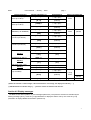
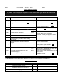
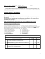
1
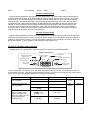
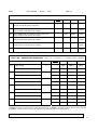
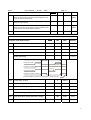
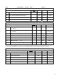
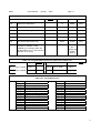
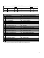
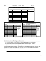
Be42
User's Manual - January - 2009
page 1
Be42 User’s Manual
The information in this document is subject to change without notice.
No part of this document may be copied or reproduced in any form or any means without the prior written
consent of Bernini Design company. Bernini Design assumes no responsibility for any errors which may appear
in this instruction manual or in the wiring diagrams.
Although Bernini Design has taken all possible steps to ensure that the User Manual is complete, bug free and
up-to-date, we accept that errors may occur. If you encounter problems with this instruction manual, please
complete this form and send it back to us.
FAX Message (++39 0386 31657), From:________________________________________
Name:_____________Company:_____________________Tel/Fax:___________________
I would like to report the following error: _______________________________________
__________________________________________________________________________
Customer Support BERNINI DESIGN SRL ITALY
e-mail: [email protected]
mobile: ++39 335 7077148. Tel:++39 0386-31445 (fax 31657).
Warranty
Bernini Design SRL (hereinafter "BD") warrants that Be42 shall be free from defect in material or workmanship
for a period of 3 years from the BD delivery date. BD shall, at its option, repair or replace the product without
charge. BD shall return the Be42 to the buyer with the Default parameters at no extra charge. The buyer shall
furnish sufficient information on any alleged defects in the product, so as to enable BD to determine their cause
and existence. If the Be42 is not defective, or the product is defective for reason other than covered by this
warranty, the buyer will be charged accordingly. This warranty shall not apply if the Be42 has not been used in
accordance with the User Manual and other operating instruction, particularly if any defects are caused by
misuse, improper repair attempts, negligence in use or handling.
This purchase is non-refundable.
This equipment complies with the EMC protection requirements
WARNING!! High voltage is present inside the Be42. To avoid electric-shock hazard, operating
personnel must not remove the protective cover. Do not disconnect the grounding connection. The Be42
can start the engine at anytime. Do not work on equipment, which is controlled by the Be42. When
servicing the engine, disconnect the battery and battery charger. We recommend that warning signs be
placed on equipment indicating the above.
1
Be42
User's Manual - January - 2009
page 2
Alphabetic index of the sections (see also alphabetic index on page 3)
Alternator Failure E04 ......7.02B [P.15]
Alarms................................4.10, 8.0
Alarm output control........ 7.09, [39]
Alarm inputs......................7.06, 8.0
Automatic ..........................2.3
Battery, Alarms.................4.10 [Er.13]
Belt break .........................4.10 [Er.02]
Choke, control ..................Table 7.03 [P.22]
Charger Alternator............11.0, 7.03 [P.26]
Contactor...........................2.21
Display ...............................3.0
Display Messages ............4.10, 4.20
Er.0.. Error codes .............4.10
[FAIL] Memory error.........4.10 [FAIL]
Emergency input ..............4.10[Er.08]
Fail to Start........................4.10[Er.11]
Fail to Stop ........................4.10[Er.07]
Front Panel........................1.0 Figure 1
Frequency .........................7.02A [P.11][P.12]
Fuel Level ..........................7.04 [P.36 - - 38]
Generator Voltage ............7.02 [P.9] [P.10]
Generator Frequency .......7.02 [P.11] [P.12]
Generator Failure E04 ......7.02B [P.15]
Glow Plugs ........................7.03 [P.22]
Hi-U, Over Voltage............7.02A [P.10]
Hour Counter ....................3.0
LED, LEDs .........................5.0
Lamp Test..........................5.1
Lo-U, Under Voltage.........7.02A [P.09]
Lock, Remote Lock E03...4.10
Low Battery voltage .........4.10,[Er.13]
Messages (Display).............4.0
Manual ..................................2.2
Oil pressure ........................7.03B [P.29]
Operating modes.................2.0
Overload...............................4.10 [Er.05]
Overload (external) .............7.07 [20][21]
Over Frequency...................4.10 [Er.01]
Over Voltage HI-U................4.10 [HI-U]
Parameters...........................7.0
Parameters reading ............6.0
Periodic test.........................7.05A [P.41][P.42]
Pre Glow...............................7.03[P.22]
Push buttons .......................2.0, 2.2
Rest time ..............................7.03A [P.21]
Rent Programming..............7.05B [P.47]
R.P.M...................................7.02B [P.16]
Settings (Parameters).........7.0
Start ......................................2.2
Start Attempts .....................7.03B [P.31]
Starting Failure....................4.10 [Er.11]
Stop, Stop solenoid ............7.03A [P.25]
Temperature ........................7.03B [P.30]
Test, Remote Test ..............7.07 [10] [11]
Test operating mode...........2.4
Transformer, Current..........7.02B [P.18]
Under Voltage Lo-U ............7.02A [P.09]
Under Frequency.................7.02A [P.11]
Voltage measurements.......3.0
Warm-Up time......................7.03A [P.23]
Mains Failure.....................7.01A [P.01]
Mains Restore ...................7.01B [P.02]
Mains Simulation..............7.07 [15]
Measurements ..................3.0
2
Be42
User's Manual - January - 2009
page 3
Be42 OEM's Manual - Contents
1.0 Introduction...................................................... page 4
2.0 Operating Mode selection .............................. page 4
2.1 OFF mode....................................................... page 5
2.2 MANUAL operating mode................................ page 5
2.3 AUTO operating mode..................................... page 6
2.4 TEST operating mode ..................................... page 6
2.5 PROGRAM operating mode ............................ page 6
3.0 DISPLAY measurements................................. page 6
4.0 DISPLAY messages......................................... page 7
5.0 LED indicators ................................................. page 9
5.1 Lamp and Display Test .................................. page 9
6.0 READING the parameters .............................. page 9
7.0 Programmable Parameter............................... page 9
Table 7.01A-B Mains Failure Control................... page 10
Table 7.02A-B Generator Parameters ................ page 11
Table 7.03A-B Engine Parameters ..................... page 11-12
Table 7.04 Alarms Options .................................. page 12
Table 7.05A-B Miscellaneous ............................. page 12-13
Table 7.06 Programmable Inputs ........................ page 13
Table 7.07 Input Options list................................ page 13
Table 7.08 Programmable Outputs ..................... page 15
Table 7.09 Outputs Options list ........................... page 14
Table 7.10 Oil Pressure Sensor .......................... page 15
Table 7.11 Temperature Sensor.......................... page 15
Table 7.12 Fuel Level Sensor.............................. page 15
8.0 Alarms, Warnings & Shutdowns .................... page 15
9.0 Automatic Periodic Test ................................. page 16
10.0 Panel & Genset builder notes....................... page 16
3
Be42
User's Manual - January - 2009
page 4
Section 1.0 Introduction
The Be42 integrates a 3-Phase Automatic Transfer Switch controller (A.T.S.) and a Generating Set controller.
The Be42 provides visual indication by means of LEDs and Display for Fuel Level, Engine & Electrical
parameters, Alarms and Status of the contactors. It features 7 Operating modes and provides a RS485 interface
for remote control & monitoring. The version Be42-N does not indicate Oil pressure / Temperature and Fuel
Level. Specifications or notes about BE42-N will be indicated with the notation ‘(**)’. Figure 1 presents the panel
layout.
Figure 1: Front Panel layout
Alarm
acknowledge
pushbutton
Display control
& indicators
Alarm
messages
F10
A
V
Hz / R.P.M.
Engine
h / Prog.
F9
F8
F1
F2
Manual Engine
Control
F3
F4
F6
F5
F7
Operating Mode
pushbuttons & LEDs
Contactors
Control
Section 2.0 Operating Mode selection
The operating modes are selected by pushbuttons and indicated by means of green LEDs:
Operating Modes Pusbuttons
Operating Modes
MANUAL Mode
green LED
MAN
Pushbutton
TEST Mode
green LED
AUTO Mode
green LED
OFF
OFF
TEST
TEST
AUTO
AUTO
Pushbutton
Pushbutton
Pushbutton
Every time the power supply is switched on, the Be42 returns to the “AUTO” operating mode, if the BE42 was in
TEST or AUTO prior to power down. In the other cases, the Be42 will enter the OFF mode. The following table
indicates the operating modes.
4
Be42
User's Manual - January - 2009
page 5
2.1 OFF mode
Push the [OFF] pushbutton to enter this operating mode. OFF mode clears the fault alarms and allows you to
read the parameters (section 6.0). The Display and LEDs are turned off and a dot on the display will blink slowly.
Push one of the pushbuttons on the front panel to energize the display.
2.2 MANUAL operating mode
The MANUAL operating mode allows you to manually control the Engine and Contactors.
Instructions
Push the [MAN] pushbutton to select the MANUAL mode (if in
AUTO mode, push the OFF button first). Push the [START]
pushbutton until engine starts; the display indicates the message
[. . . .] during the starting attempts (and [! ! ! !] during the preheat).
When the engine is running, the green LED turns on. To stop the
engine, push the [STOP] pushbutton until the [StOP] message
appears on the display. If the engine has already stopped, it is
possible to reset the STOP sequence by pressing the [STOP]
pushbutton.
Manual Engine Control
Engine Running
green LED
STOP
Pushbutton
START
Pushbutton
2.21 Manual Control of the LOAD
To control the contactors follow the instructions:
Contactors Control Panel
Generator
Presence LED
(Green)
KG-closed
indicator
(Green)
Instructions
KM-closed
indicator
(Green)
KG
Mains
Presence LED
(Green)
KM
KM
Pushbutton
(push to close)
KG
Pushbutton
(push to close)
[ O ]Pushbutton
(push to open)
Select the MANUAL mode, start the engine (see
above) and wait until the ‘Generator Presence’
green Led turns on.
Push the [ I ] (KG) pushbuttons to close the
contactor of the Generator. To transfer the Load
to Mains, push the [ I ] (KM) pushbutton (the [KG]
will open after a short delay).
To open a contactor, push the [O] pushbutton at
anytime.
! ! WARNING ! !
LINE VOLTAGE IS EXPOSED WITHIN THE Be42, THE LOAD OR ANCILLARY CIRCUITRY EVEN WHEN
THE GREEN LEDs ARE TOTALLY OFF
5
Be42
User's Manual - January - 2009
page 6
2.3 AUTO operating mode
Push the [AUTO] pushbutton until the green LED will illuminate. The engine starts when the Be42 detects
a Mains failure. The contactor of the MAINS (KM) opens after a delay. After the warm-up time, if the Voltage
and Frequency are within the settings, the contactor of the Generator (KG) will close. If the Mains restores,
the KG will open. The KM will close after a programmable changeover timing. The Engine will stop after a
cooling down time. If the engine shuts down, the KM will close only if the Mains is within the programmed
settings. In AUTO operating mode, the Be42 will periodically test the engine if the parameters [P.41] and
[P.42] have been programmed (see section 6.0). During this test, the green LED of the AUTO operating
mode will continue to blink. In AUTO operating mode, the Be42 can start and stop the engine according to
programmable inputs (ask to your Panel manufacturer).
2.4 TEST operating mode
Push the [TEST] pushbutton until the green LED will illuminate.The Be42 starts the engine and transfers the
load to the Generator if the [P.17] is [on]. To stop the engine, select the AUTO operating mode (if the Mains is
present) or select the OFF mode. If you push the [STOP] pushbutton when the Be42 is in AUTO or TEST, the
[Er.09] will energize. To clear the alarm, select the OFF mode (section 8.0).
Section 3.0 Display measurements
The Be42 features a 4 Digit display, two pushbuttons and 5 yellow Leds as indicated below.
Display and Menus
Frequency-Speed
Display menu
Vac-Generator-Mains
Display menu
Generator-Current
Display menu
[ F8 ] control
Pushbutton
A
V
Hz / R.P.M.
Engine
F8
OIL-°C-%FUEL-Vb
Display menu
h-count - Programming
Display menu
h / Prog.
F9
[ F9 ]
Display control
Pushbutton
4Digit Display
Use [←F8] and [F9→] to select a menu. Use [ACK-F10] (see the layout in section 1.0) to display the name of
the parameter. The OFF mode shuts down the display and turns on the dot on the right side of it. Push a button
to turn on the panel. The following table lists the functions of the display.
Display Function
Current of the Generator
(0 up to 2000A)
Voltage of the Generator
(60V up to 998V)
Display indications (*)
[XXXX] Ampere
Pushbutton(s)
[A -G]
[ACK-F10]
[GXXX]
Volt L1-L2
[U -G]
Voltage of the Mains
(60V up to 998V). If the
Mains is simulated, see
otion [15] in table 7.07, the
display will show the
message [U-on]
[nXXX] (VL1-2)
[-XXX] (V L2-3)
[_XXX] (L1-L3)
[U -on]
[←F8] or [F9→]
[←F8] or [F9→]
Menu & Led indicator
Aac
Yellow
menu
Vac
menu
Yellow
[ACK-F10]
[←F8] or [F9→]
[ACK-F10]
6
Be42
User's Manual - January - 2009
Display Function
Generator Frequency
(20Hz up to 70Hz)
page 7
Display indications (*)
[GXXX] Hz
Pushbutton(s)
[H - G]
[ACK-F10]
[nXXX] Hz
[←F8] or [F9→]
Mains Frequency
(20Hz up to 70Hz)
[H - n]
Speed
(600RPM up to 4000RPM)
Battery Voltage
(5,5 Vdc up to 36Vdc)
Charger Voltage
(3.0 Vdc up to 36Vdc)
Oil Pressure 0.0-20.0 Bar
[←F8] or [F9→]
[ACK-F10]
[XXXX] RPM
[←F8] or [F9→]
[SPd]
[ACK-F10]
[bXX.X] Vdc
[←F8] or [F9→]
[batt]
[ACK-F10]
[cXX.X] Vdc
[←F8] or [F9→]
[Char.]
[ACK-F10]
[PXX.X] Bar
Menu & Led indicator
Hz/RPM
Yellow
menu
Hz/RPM
menu
Yellow
(blinks)
Engine
Yellow
[←F8] or [F9→]
NOTE (**)
[ bar ]
Temperature 0°-250 °C
NOTE (**)
Fuel Level % 0% - 99%
NOTE (**)
Hours-count
(0 up to 9999h)
OFF
[XXX °] °C
[ACK]
[←F8] or [F9→]
[ °C ]
[ACK]
[F XX] %
[←F8] or [F9→]
[FUEL]
[XXXX] h
[ACK-F10]
[←F8] or [F9→]
[Hour]
[ACK-F10]
h/Prog
menu
[OFF-F7]
OFF
[
.]
Yellow
Yellow
(blinks)
OFF
(*)NOTE: X indicates a numerical digit, if the measurement is out of range, the display will indicate [- - - -]
(**)NOTE: Be42-N will indicate always [- - - -] beacuse it does not interface with sensors.
Section 4.0 Display messages
The Be42 shows alarms (table 4.10) and messages (table 4.20). The presence of alarms is indicated by the
blinking message [ ALAr.]. Push the [→F9] pushbuttons to display the alarms one by one. Push the [←F8]
pushbutton to display additional information (section 8.0).
7
Be42
User's Manual - January - 2009
page 8
Table 4.10: Alarm messages
( !!! ) NOTE: consult always your supplier or the user manual of the engine. A short description of the
alarms is indicated below.
Display
Description of the Alarm
Display
Description of the Alarm
[Er.01]
Over Frequency Shutdown
( °°° )
[Er. 14]
Low Oil Pressure Shutdown
[Er.02]
Engine Belt Break Shutdown
( !!! )
[Er. 15]
Temperature Switch Shutdown
[Er.03]
Remote LOCK Shutdown.
[Hi-C]
[Er.04]
Alternator Failure Shutdown
( !!! )
[Hi-U]
Over Current Shutdown or Warning (push
[←F8] to display the value).
( °°° )
Over Voltage / Under Voltage Shutdown
[Er.05]
Overload Warning or Shutdown
( °°° )
[Lo-U]
[Er.06]
Under Frequency Shutdown
( °°° )
[InP.2]
[Er.07]
Fail To STOP Shutdown
( !!! )
[InP.3]
[Er.08]
[Er.10]
Emergency Shutdown. (Wait for the end
of the Emergency condition before starting
the engine).
Emergency Shutdown from the Front
Panel. (Cancel the Alarm and restart the
engine).
Maintenance SERVICE warning ( !!! )
[Er.11]
Fail To START Shutdown
[InP.1]
[Er.09]
( !!! )
[Er. 13]
Low Fuel Shutdown (Fill the tank and
restart the engine)
Battery Voltage Warning
( !!! )
( !!! )
( °°° )
Input 1-2-3-4 Shutdown / Warning
Normally these alarms protect your
Generator. Consult your supplier for further
details.
[InP.4]
[-oIL] (**)
Oil pressure warning or sensor failure. Push
[←F8] to display the value.
( !!! )
[ -°C] (**)
Water temperature warning or sensor failure.
Push [←F8] to display the value. ( !!! )
[FUEL]
Fuel level warning (High or Low) or sensor
failure. Push [←F8] to display the value. (Fill
the tank and restart the engine)
Push [←F8] to display the remaining hours of
Rent contract.
There is an internal failure or memory error in
the BE42 controller
( !!! )
(**)
[Er.12]
( !!! )
[rEnt.]
[FAIL]
( °°° ) NOTE: verify if you are Overloading the Generator: consult an electrician.
l
(**)NOTE: Be42-N will note indicate these messages; this controller does not interface with the Sensor.
4.20 Operating messages
Message
[rESt]
[n-on]
['''']
[StoP]
Description
The Be42 is counting the rest time
between the starting attempts
MAINS Simulated. A programmable input
simulates the presence of the Mains.
The Be42 is performing the pre-glow
The Be42 is stopping the engine
Message
[ProG]
Description
The Be42 is in program mode
[-CAL]
The Be42 is in calibration mode
[. . . .]
[tEst]
[----]
The Be42 is performing the start
The Be42 is in Troubleshooting mode
The measurement is not available
8
Be42
User's Manual - January - 2009
page 9
Section 5.0 LED indicators
5.1 Lamp and Display Test
To test the LEDs and DISPLAY push the [OFF] pushbutton; the display turns off. Push and hold the [←F8]
and [F9→] pushbuttons simultaneously. The LEDs and DISPLAYs remain energised as long as the pushbuttons
are pressed and held together.
Section 6.0 Reading of the Parameters
To read the setting of the parameters, follow the instructions:
1) - Press the [OFF] pushbutton until the LEDs and display turn OFF.
2) - Push the [←F8] or [F9→] pushbutton to select a parameter (section 7.0).
3) - Push [START-F1] to display the setting of the parameter (example: [P.10] = [450]; the Overvoltage limit is
set to 450Volt).
4) - Push [STOP-F2] to display the setting of the sub-parameter (example: [P.10] = [2'']. The timing delay of
Overvolatge is set to 2 seconds).
5) - Push the [←F8] or [F9→] pushbutton to select another parameter.
NOTE: if the pushbuttons remain inoperative for more than 5 minutes, the Be42 enters the OFF mode.
Section 7.0 Programmable Parameters
You are not allowed to program the controller. You can read the setting of the paramaters. If you need
information contact the manufacturer of your panel. The parameters are divided into classes as indicated below.
We recommend that you read the parameters and record the settings on this paper (use the Setting column).
Allowed settings are indicated in the columns ‘Min’, ‘Max’ and ‘Options’.
7.01A, B - Mains Failure Control
7.02A, B - Generator Parameters
7.03A, B - Engine Parameters
7.04 - Alarms Options
7.05A, B - Miscellaneous
7.06 - Programmable Inputs
Table 7.01A - Mains Failure Control
7.07 - Input Options List
7.08 - Programmable Outputs
7.09 - Output Options table
7.10 - Oil Pressure Sensor
7.11 - Temperature Sensor
7.12 - Fuel level Sensor
Note: [ xx " ] = seconds, [ xx ' ] = minutes, [xxh ] = hours
Parameter Code & Description
P.0 Mains Contactor control (KM). If the Mains Failure persists for more than [P.0]
Setting
Min
Max
0
59mins
0
23h
0
23h
(seconds or minutes), the Mains contactor will open and the [P.1] timer will start to
count. The Mains contactor will close only after the [P.2] timing.
P.1 Mains Failure time. After the [P.0] timing (see above), the engine will start if the
Mains Failure persists for the [P.1] time.
P.2 Mains Restore time. The Be42 transfers the Load to the Mains once the MAINS is
stable for at least [P.2] (seconds, minutes or hours) . During [P.2] , the engine will
continue to run ON-LOAD. After [P.2], the [P.24] timer will take place to run the engine
OFF-LOAD (the contactor of the generator will open)
9
Be42
User's Manual - January - 2009
page 10
Table 7.01B - Mains Failure Control Note: [ xx " ] = seconds, [ xx ' ] = minutes, [ oFF ] = disabled
Parameter Code & Description
Setting
P.3 Contactors changeover. This timing introduces a delay
Min
Max
Options
0.1secs 15.0secs
-
between the switching of the contactors.
P.4 Under voltage limit. If the Phase-to-Phase voltage falls
60V
998V
60V
998V
20.0Hz
70.0Hz
20.0Hz
70.0Hz
-
-
[oFF]
under this limit, the [P.0] timer will energise.
P.5 Over voltage limit. If the Phase-to-Phase voltage rises
[oFF]
above the limit, the [P.0] timer will energise.
P.6 Under Hz limit. If the Phase-to-Phase frequency falls
[oFF]
under the limit, the [P.0] timer will energise.
P.7 Over Hz limit. If the Phase-to-Phase frequency rises
[oFF]
above the limit, the [P.0] timer will energise.
P.8 Phase Selection. It allows a 3-Phase or Single Phase control
Table 7.02A - GENERATOR PARAMETERS
Parameter Code & Description
P.9
Note: [ xx " ] = seconds, [ xx ' ] = minutes, [ oFF ] = disabled
Mode (°)
Under voltage
1
Under voltage delay
P.10 Over voltage
2
Over voltage delay
P.11 Under Frequency
1
Under Frequency delay
P.12 Over Frequency
2
Over Frequency delay
P.13 Warning current limit
3
Warning current delay
P.14 Over current shut down
Over current shut down delay
[3-Ph]
[Ph-n]
1
Setting
Min
Max
Options
60V
998V
[oFF]
1sec
15secs
-
60V
998V
[oFF]
1sec
15secs
-
20.0Hz
70.0Hz
[oFF]
1sec
15secs
-
20.0Hz
70.0Hz
[oFF]
1sec
15secs
-
10A
2000A
[oFF]
1sec
15mins
-
10A
2000A
[oFF]
1sec
15mins
-
(°) Mode1: The engine shuts down,after a cooling down time ([P.24]). (°) Mode2: The engine shuts down without a cooling down time.
(°) Mode3: The Be42 provides a warning if the parameters rises above the setting for the specified timing.
Table 7.02B - GENERATOR PARAMETERS
Note: [ oFF ] = disabled, [ on ] = enabled
10
Be42
User's Manual - January - 2009
Parameter Code & Description
page 11
Min
Max
Setting
P.15 Alternator failure options. The alarm [E04] energises if the
Options
-
-
[on]
[oFF]
2
4
-
-
-
[on]
[oFF]
50A
2000A
-
voltage (or the frequency) is lower than the setting of P.9 (or
P11) for more than 150 seconds.
P.16 Alternator number of Poles. Options [2] or [4] allow you to
display the engine speed.
P.17 Generator Contactor Control. The option [off] inhibits the
transfer of the load to the generator in TEST operating mode
(or remote TEST) when the MAINS is present.
P.18 CT size (/5Aac).
Table 7.03A - ENGINE PARAMETERS Note: [ xx " ] = seconds, [ xx ' ] = minutes, [ oFF ] = disabled
Setting
Parameter Code & Description
Min
Max
Options
P.19
Crank delay
0
15secs
-
P.20
Crank time
1 sec
15secs
-
P.21
Rest time
3secs
15secs
-
P.22
Pre-glow time
1sec
59mins
[ oFF ]
-
-
1-2-3-4
Modes (see below)
Starting Motor
Pre-glow mode 1
[ P.20 ]
Total rest timing
[ P.22 ]
[ P.22 ]
Pre-glow mode 2
[ P.21 ]
Pre-glow mode 3
Pre-glow mode 4 (Choke)
[ P.22 ]
Crank termination (engine running detect) [ P.26]..27]..28 ]
P.23
Engine Warm up time
0
59mins
-
P.24
Engine Cooling time
0
59mins
-
P.25
Stop Solenoid timing (Energized to stop)
1sec
59mins
-
P.26
Crank termination setting (Charger Alternator)
3.0V
30.0V
[oFF]
Belt break setting (Charger Alternator)
3.0V
30.0V
[oFF]
P.27
Crank termination setting (Generator Voltage)
60V
998V
[oFF]
P.28
Crank termination (GeneratorFrequency)
20.0Hz
70.0Hz
[oFF]
11
Be42
User's Manual - January - 2009
page 12
Table 7.03B - ENGINE PARAMETERS Note: [ xx " ] = seconds, [ xx ' ] = minutes, [ oFF ] = disabled
Setting
Parameter Code & Description
P.29
Low Oil pressure warning (**)
P.30
High engine temperature warning (**)
P.31
Crank attempts (numbers)
P.32
Purge timing (for Gas fuelled engine)
Min
Max
Options
0.1Bar
20.0 Bar
[oFF]
40°C
250°C
[oFF]
3
15
-
1sec
15secs
-
Table 7.04 - ALARM OPTIONS Note: [ xx " ] = seconds, [ xx ' ] = minutes, [ oFF ] = disabled
Setting
Parameter Code & Description
Min
Max
Options
2secs
90secs
-
P.33
Alarms bypass (for oil, temperature, auxiliary12-3-4 alarms)
P.34
Fail to stop alarm control (oFF = inhibited,
on = enabled)
-
-
[oFF]/ [on]
P.35
Emergency contact type (Input #36)
-
-
[n.o. / n.c.]
P.36
No fuel in the tank delay
15secs
99mins
[oFF]
P.37
Low fuel % limit
(**)
1%
99%
[oFF]
P.38
High fuel % limit
(**)
1%
99%
[oFF]
P.39
Engine temperature contact type
-
-
[n.o. / n.c.]
(**) The controller BE42N will not allow you to modifify the [OFF] setting (it does not support sensors)
Table 7.05A - MISCELLANEOUS Note: [ xx " ] = seconds, [ xx ' ] = minutes, [ oFF ] = disabled
Parameter Code & Description
Setting
Min
Max
Options
P.40
EJP time
1 sec
99 mins
-
P.41
Periodic Test interval
1 Day
60 Days
[oFF]
P.42
Periodic Test duration
1 min
99 mins
-
P.43
Test timeout ([OFF= no timeout)
1 min
99 mins
[oFF]
P.44
Maintenance SERVICE 1
1h
9999h
[oFF]
12
Be42
User's Manual - January - 2009
page 13
Table 7.05B - MISCELLANEOUS Note: [ xx " ] = seconds, [ xx ' ] = minutes, [ oFF ] = disabled
Setting
Parameter Code & Description
Min
Max
Options
P.45
Maintenance SERVICE 2
1h
9999h
[oFF]
P.46
Maintenance SERVICE 3
1h
9999h
[oFF]
P.47
Rent Contract Setting
1h
9999h
[oFF]
P.48
NFPA - 110 Level 1&2
-
-
[on]/[oFF]
P.49
RS485 Node Address
1
127
-
P.50
Horn timeout (see section 8.0)
5secs
15mins
[oFF]
P.51
Hour Counter set (over 9999, a dot
will appear to indicate a value
multiplied by10. Example 3250. will
indicate 32500 hours. In this case the
relosultion is 10 hours)
0h
50.000
[oFF]
(the
display will
indicate
[5000.])
Table 7.06 - Programmable inputs (see options list in table 7.07)
Parameter
Options
Setting
Parameter
Options
[InP.1]
Input 1/ Mode [n.o.][n.c.]
[InP.3] Input 3 / Mode
[n.o.][n.c.]
[InP.2]
Input 2 /Mode [n.o.][n.c.]
[InP.4] Input 4 / Mode
[n.o. ][n.c.]
Setting
Table 7.07 - Input Options List
Option
[0]
[1]
[2]
[3]
[4]
[5]
[6]
[7]
[8]
[9]
[ 10 ]
[ 11 ]
[ 12 ]
[ 13 ]
Option
Off: disables the input
Immediate Stop
Bypass and Stop
Cooling and Stop
Bypass+Cooling and Stop
Warning only
Bypass and Warning
Remote Manual Mode
Remote Auto Mode
Remote Off Mode
Remote Engine Test
Remote Generator Test
Ejp function
Remote LOCK
[ 14 ]
[ 15 ]
[ 16 ]
[ 17 ]
[ 18 ]
[ 19 ]
[ 20 ]
[ 21 ]
[ 22 ]
[ 23 ]
[ 24 ]
[ 25 ]
[ 26 ]
Generator simulation ON
Mains Simultation ON
Front panel LEDs test
Alarm acknowledge
Display Right Pushbutton
Display Left Pushbutton
Overload Input Warning
Overload Input Shutdown
KG Forced closed
KM Forced closed
KG LED Feedback
KM LED Feedback
Idle Engine
13
Be42
User's Manual - January - 2009
7.08 - Programmable Outputs
Parameter Code & description
Setting
page 14
Parameter Code &description
Setting
Options
[Out.1]
Output 1
[Out.3] Output 3
see 7.09
[Out.2]
Output 2
[Out.4] Output 4
see 7.09
Table 7.09 - Output Options Table
Option & description
Option & description
[ 0 ] Output is disabled
[32]
Alarm form Input 2: Shutdown/Warning
[ 1 ] Under Frequency Shutdown
[33]
Alarm form Input 3: Shutdown/Warning
[ 2 ] Over Frequency Shutdown
[34]
Alarm form Input 4: Shutdown/Warning
[ 3 ] Over Current Shutdown
[35]
Cumulative Oil Alarms
[ 4 ] Over Current Warning
[36]
Cumulative Temperature Alarms
[ 5 ] Overload Warning or Shutdown
[37]
Cumulative Alternator Alarms
[ 6 ] Over Voltage Shutdown
[38]
Common Fuel Alarms
[ 7 ] Under Voltage Shutdown
[39]
Horn Output
[ 8 ] Alternator Failure Shutdown
[40]
Crank Delay (Start Warning)
[ 9 ] Low Oil Pressure Warning (**)
[41]
Presence of Nominal Mains Parameters
[10] Low Oil Pressure Shutdown
[42]
Mains Failure Timing
[11] Oil Sender Failure Warning (**)
[43]
Mains Restore Timing
[12] High Temperature Warning (**)
[44]
KG Status
[13] Temperature Switch Shutdown
[45]
KM Status
[14] Temperature Sender Failure Warning (**)
[46]
Pre-glow MODE 1/2/3/4
[15] Low Battery Voltage Warning
[47]
PURGE (gas engine valve control)
[16] High Battery Voltage Warning
[48]
RENT<48h
[17] Low Fuel Shutdown (switch)
[49]
RENT=0h (Expired)
[18] Fuel Low Warning (sensor) (**)
[50]
Engine Running Status
[19] Fuel Reserve Warning (switch)
[51]
Presence of Nominal Generator Voltage
[20] Fuel high Warning (sensor) (**)
[52]
BE42 in OFF MODE (Status)
[21] Fuel Sender Failure Warning (**)
[53]
BE42 in MANUAL MODE (Status)
[22] Emergency Stop Shutdown (Er08)
[54]
BE42 in AUTO MODE (Status)
[23] Stop Pushbutton Used in AUTO (Er09)
[55]
BE42 in TEST MODE (Status)
[24] Maintenance SERVICE 1 (Er10)
[56]
BE42 in LOCK MODE (Status)
[25] Maintenance SERVICE 2 (Er10)
[57]
Automatic Periodic Test
[26] Maintenance SERVICE 3 (Er10)
[58]
Cooling Timing
[27] Engine Belt Break Shutdown
[59]
Warm up Timing
[28] Fail To START Shutdown
-[29] Fail To STOP Shutdown
-[30] Indication of Parameter Error warning
-[31] Alarm form Input 1: Shutdown/Warning
-(**) This option will not trigger the output of the BE42N (it does not support sensors)
14
Be42
User's Manual - January - 2009
page 15
Table 7.10 - Oil Pressure Sensor Settings (**)
Display
Parameter
[Pr.1]
[-r1-]
[Pr.2]
[-r2-]
[Pr.3]
[-r3-]
[Pr.4]
[-r4-]
[Pr.5]
[-r5-]
[Pr.6]
[-r6-]
Pressure
Resistance
Pressure
Resistance
Pressure
Resistance
Pressure
Resistance
Pressure
Resistance
Pressure
Resistance
Setting
0 up to 20 Bar
0 up to 2000
Ohm
7.11 - Temperature Sensor (**)
Display
[°C1]
[-r1-]
[°C 2]
[-r2-]
[°C 3]
[-r3- ]
[°C 4]
[-r4- ]
[°C 5]
[-r5- ]
[°C 6]
[-r6- ]
Parameter
Temperature
Resistance
Temperature
Resistance
Temperature
Resistance
Temperature
Resistance
Temperature
Resistance
Temperature
Resistance
Setting
Range
0°C up to
250°C
0 Ohm up
to 2000
Ohm
Range
7.12 - Fuel Level Sensor (**)
Display
Parameter
[FUE1]
[-r1-]
[FUE2]
[-r2-]
[FUE3]
[-r3-]
[FUE4]
[-r4-]
[FUE5]
[-r5-]
[FUE6]
[-r6-]
Fuel Level
Resistance
Fuel Level
Resistance
Fuel Level
Resistance
Fuel Level
Resistance
Fuel Level
Resistance
Fuel Level
Resistance
Setting
Range
0% up to
99%
0 Ohm
up to
2000
Ohm
(**) These parameters are not availbale on the controller BE42N (it does not support sensors)
Section 8.0 - Alarms, Warnings and Shutdowns
The Be42 features Shutdowns (the engine stops) and Warnings (the engine will continue to run) and provides:
A) - a general indication of alarm presence by means of the message [ALAr.] on the display
B) - symbols and ideograms on the front panel to indicate alarms (see Figure 1, section 1)
C) - display messages indicating warnings and shutdowns (see Table 4.1)
D) - a pushbutton to silence the Horn ( [ACK-F10] )
To silence the HORN (if provided by your Panel manufacturer), push the [ACK-F10] pushbutton.
To browse the alarm memory push the [→F9] pushbutton. To display details about the alarm, push the [←F8]
pushbutton. To clear the alarm from the panel, remove the cause of the alarm and then press the [OFF]
pushbutton. The Table 4.10 in section 4.0 indicates all alarms.
!!! WARNING !!! In case of Alarm consult always your supplier or the user manual of the engine
15
Be42
User's Manual - January - 2009
page 16
Section 9.0 Automatic Periodic Test
The Be42 does not use an internal real time clock for the programmed days of automatic test. To see if your
controller is programmed with a Periodic Test, enter the READING PARAMETER MODE and read the setting of
[P.41] (table 7.05). You could experiment with shifting the periodic tests. To avoid error accumulation, we
recommend the following procedures.
A) - Power off the controller (if a switch is provided by your panel manufacturer) or disconnect the battery.
B) - Connect the supply and select the 'AUTO' operating mode.
The Be42 will start the engine after the programmed days. The engine will run OFF-LOAD for the time
programmed in the [P.42] (Periodic test duration). If the Mains fails during the Periodic Test, the Be42 will
transfer the load to the generator.
IMPORTANT NOTICE If the Vdc supply is removed, the Be42 looses the counts of the days. If the supply
restores, the Be42 starts to count the days from zero. To synchronize the periodic start follow the instruction of
the section 9.0
!! WARNING !!
High voltage is present inside the Be42. To avoid electric-shock hazard, operating personnel must not
remove the protective cover. Do not disconnect the grounding connection. The Be42 can start the
engine at anytime. Do not work on equipment, which is controlled by the Be42. When servicing the
engine, disconnect the battery and battery charger. We recommend that warning signs be placed on
equipment indicating the above.
10.0 - Panel & Gen-set Builders Notes
________________________________________
________________________________________
________________________________________
________________________________________
11.0 - SUPPORT & ASSISTANCE
You can contact us at anytime:
[email protected]
[email protected]
24h/24h worldwide: +40 721 241 361 or +39 335 7077148
16