1
The Solar Array
Hardware
The solar array is made up of 42 panels each rated at 0.5V and 125mA in noon sunlight.
Each individual cell contains a solder strip on the top that is the negative terminal and
anywhere on the back of the panel is the positive terminal. The cells are soldered
together in a manner to get a voltage that is higher than the battery voltage at full charge
and to get the highest possible amount of current. This is done by wiring three sets of 14
cells in series. Then each one of these cells is solder together in parallel to produce a
theoretical 7V @ 375mA in full noon sun.
To stop current from flowing back into the solar cells and wasting energy, diodes were
placed on the positive terminal of each of the 3 series sets. The diodes that were used are
1N4003 diodes rated at 12V @ 1A maximum which is below the maximum output the
solar array can produce.
The cells are attached to a 6”x8” piece of perf-board using foam double sided tape. They
are arranged in six rows of seven to fit on the perf-board with little room to spare. All of
the spare wire is taped to the perf-board using electrical tape to prevent short circuits
The perf-board is attached to the robot using 3 long bolts. Two of the bolts are attached
to the back of the BoeBot through the predrilled holes. The third bolt is attached to the
front of the robot through a precut slot that was drilled out to accommodate the girth of
the bolt. Each bolt is attached to the BoeBot and perf-board using four washers and four
nuts with one set on each side of a surface.
Light Seeking
Hardware
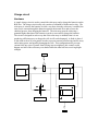
The Photoresistors that were used to design the
light seeking work by varying their resistance
with the amount of light it senses. A high
resistance indicates very low light and a low
resistance indicates bright light. A simple RC
circuit is used to measure the resistance of the
photoresistors by measuring the time it takes a
capacitor to discharge through the
photoresistor to ground. Refer to the diagram
for a schematic of the RC circuit used.
To achieve our light seeking algorithm two
photoresistors were mounted on the front
corners of the perf-board using electrical tape.
These two photoresistors worked in
conjunction for navigational purposes. Also, one resistor was placed flat on the top of the