1
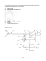
Artemis Labs
Model TA-1 Instruction Manual
Dear Customer
Congratulations! You have purchased a unique tonearm that will transcribe the most accurate
detail and provide the most musically enjoyable reproduction from your vinyl records. The
tonearm features ceramic hybrid bearings of the highest quality, reducing bearing friction to
unprecedented low levels (<2mg), insuring years of trouble free performance. To take full
advantage of this inherently superior design please take the time to study and familiarise
yourself with this manual.
I hope you will enjoy mounting and adjusting the tonearm and rediscovering your record
collection.
1. Mounting the tonearm
Mounting the arm requires drilling a 23 mm (0.90 inch) to 25mm (0.98 inch) max. hole (Rega
mounting) in your plinth or armboard plus a single (tapped) hole for the mounting screw (A.1,
non-magnetic M6, supplied with the arm).
The pivot to spindle distance for your arm measures 222mm. Please study the mounting
schematic for the correct placement of the teardrop shaped mounting collar (A) and its
mounting screw. Deviations from the suggested orientation are permissible as long as the
mounting collar (A) doesn't interfere with the arm's counterweight, while maintaining the p-s
distance of 222mm.
Once you have found a suitable position and drilled/tapped the M6 hole, screw the mounting
collar (A) to the base or plinth of your tonearm using the supplied M6 screw or, if your turntable
features a wooden plinth, a suitable brass or stainless wood screw.
If you need to secure your arm (i.e. when carrying the turntable around), please use a rubber
band. The arm doesn't feature a locking mechanism as these always leave marks with time
AND resonate. There is no rsk omitting this feature as the arm's design doesn't allow for the
cartridge to be “dropped” onto the plinth or mounting board.
Page 1
The following schematics will help you to identify the tonearm parts including the set screws
necessary to properly align your arm and cartridge:
A:
Mounting collar
A.1: Mounting screw, M6, cylinder head
A.2: Mounting collar set screw
B.:
Arm shaft
C:
Lift holder bar
C.1: Antiskating adjustment screw
D, D.2: Counterweight
D.1: Counter weight set screw
E:
Armwand receptacle
E.1: Armwand set screw
F:
Armwand
F.1: Headshell section
F.2: Headshell set screw
G:
Headshell, cartridge mounting plate
H:
Arm lift
H.1: Lift bank
I:
Skating compensation screw
Arm seen from left:
Page 2
Arm seen from right:
Armwand/counterweight assembly, seen from above:
2)
The tonearm wiring
This tonearm comes standard with a cable that was chosen for it’s sonic and mechanical
properties. The signal is carried in a single run from the cartridge clips to the headamp or
phonostage omitting additional soldered connections..
The wiring exist the tonearm shaft through a disc that acts as a strain relief. Do not loosen either
of the two set screws on the lower end of the shaft or the disc at its very end as this will disable
the strain relief.
Page 3
3)
Electrical connections, grounding
The conductors/connectors are colour-coded according to the international standard:
Red = right channel, hot ; green = right channel, ground ; white = left channel, hot ; blue = left
channel, ground .
RCA plugs: red = right channel ; black = left channel
The standard wiring is shielded from the arm to the RCA-plugs. The “ground” wire is to be
connected to the following amplification stage’s “ground”. If you use a “star grounding” pattern,
connect the ground wire to your “central” ground.
4)
Adjusting your tonearm/cartridge
4.1)
Alignment of the arm relative to the turntable
After the arm collar (A) has been screwed down to the arm board or plinth (excessive force is
not required), first insert the wiring, then the shaft (B) into the collar (A) as far as it is required to
end up with the armwand (F) roughly parallel to the platter. Then turn the shaft (B) so the
tonearm in its resting position (armwand at rest close to the right end of the lift bank) will be
parallel to the right side of the turntable plinth or so it's visually agreeable if your turntable has
an irregular or circular shape. Any position is fine as long as the armwand will be within range
of the liftbank throughout the usable record radius.
4.2)
Mounting your cartridge
The cartridge can be mounted to the cartridge mounting plate( G), using the supplied M2.5 nonmagnetic stainless steel screws while the plate is “off” the tonearm. First separate the mounting
plate (G) from the armwand by unscrewing the headshell set screw (F.2) . Usually it is sufficient
to tighten the M2.5 screws well, but not excessively so. Over tightened screws can result in
internal tensions in the cartridge body, negatively affecting the sound or even damaging the
internal structure. Don’t forget: the next step after “REALLY tight” is “totally loose” :-(.
Connecting the mounting plate (G) with the armwand requires re-tightening the headshell set
screw (F.2). The applied torque should be varied from just finger tight to “reasonably” tight,
excessive application of force is not recommended (see paragraph 5).
4.3)
Tracking force, overhang and tangency (“zenith”)
Take the counter weight (D.2) and slide it onto the back section of the armwand (F). Leave your
“stylus cover” (if your cartridge features such a device) on and set the tracking force to approx.
1.5 gr. Tighten the counterweight set screw (E.1) just so that you can still slide and turn the
counterweight without applying too much pressure.
Using a proper template(i.e. Dennesen, Wallytractor, AccuTrak, Dr. Feickert or mine – which
comes with the arm), overhang is now adjusted by first loosening the screw (F.2) just so it
barely “grips”, then sliding the cartridge mounting plate (G) towards or away from the bearing.
Using the supplied alignment gauge will result in achieving a proper “outer” zero-point
(120.9mm) once you have managed to get the “inner” zero-point (66.04mm) right.
Next, check the tangency of the cantilever (at the zero-points) as seen from above/front – hold
the armlift so that the stylus is not quite touching the alignment gauge - and if necessary, raise it
Page 4
again and turn the headshell mounting plate -without sliding it forward or backward again-,
making sure the cantilever (not the cartridge body) is tangential to the record. Finally, tighten
screw (F.2) again.
If the cantilever of your cartridge is aligned perfectly parallel with the sides of the cartridge body
(rarely the case!), you'll find the front of the headshell plate to be perfectly parallel with the front
of the headshell (F.1). The cartridge mounting plate (G) has bevelled/polished edges to make it
easier to see slight deviations from parallel alignment relative to the front of the headshell (F.1).
A “non-parallel” cartridge mounting plate alignment is therefore required if the cantilever isn't
well aligned relative to the cart body.
Now set the tracking force to the value recommended by the cartridge manufacturer by sliding
the counter weight (D) again forward or backward on the end stub of the armwand. It is
recommendable to use a high quality digital gauge, but even the venerable Shure “see-saw”
gauge will yield dependable, if only low res measurements. This is because the Artemis arm is a
neutral balance design, so changes in VTA, record thickness or measuring “height” of your VTF
gauge will not change VTF setting.
4.4)
VTA/SRA (Vertical Tracking Angle/Stylus Rake Angle)-adjustment
As a starting point you should raise or lower the tonearm until the armwand (F) appears to be
parallel to the record surface with the needle in the groove.
Just unscrew the VTA-set screw (A.2), then slide the shaft (B) up or down until this has been
achieved. The fine adjustment has to be carried out using your ears. Raise or lower the arm by
small increments until you have reached a position that combines precise placement of images
with an effortless delivery of dynamic contrasts. Sibiliants should come from the same position
in space as the singer’s head, not from a point in front of it!
4.5)
Antiskating
To compensate for the skating force turn the antiskating-adjustment screw (C.1) clockwise to
increase force and counter-clockwise to reduce it. Skating compensation will always be a
compromise because the required compensation force for a given VTF depends upon the stylus
geometry, the quality of the polished contact zone, the vinyl formulation, the modulation level,
arm bearing friction, etc. The skating force compensation of the Artemis Labs TA-1 is sufficient
for a tracking force up to 2.3 gr. Upon request higher tracking forces can be compensated for by
exchanging the antiskating screw (please contact Artemis Labs). In any case a slight under
compensation is always to be preferred over even the slightest overcompensation. The use of
most test records and their “torture tracks” (>80µ) will yield too high a compensation because
there are no continuous signals of this magnitude on any record. As a start, just put the
diamond on the space between the leadout grooves (or a “blank” record, i.e. Cardas sweeper
record) and adjust antiskating until the arm/cartridge combo wanders slowly towards the center
of the record.
From then on, use your ears...
5)
The “finetuning”
Everyone who has to mount cartridges frequently understands the importance of precisely
adjusting an arm/cartridge combination to release it’s full potential.
Overhang, azimuth, VTA, tracking force and, if featured, variable damping of the arm movement
are all important parameters.
Page 5
The overhang adjustment was described already, nevertheless let me add that a single “perfect”
overhang setting does not exist. Should you own a lot of records that are cut close to the inner
groove you might consider using 63mm instead of 66mm as your inner “zero point” – many
crescendo finales of symphonic works could be tracked with reduced distortion this way.
On the other hand exist a lot of “Pop-records” with no modulation but leadout groove already
where the “inner” zero point is located. One doesn’t even benefit from this second distortion
minimum.
For an arm of 239mm eff. l. (like the Artemis TA-1 arm) a “correct” overhang adjustment (after
Baerwald) results in average tracing-error-related tracking distortion of barely more than 0.4%.
Next, the azimuth should be adjusted so that crosstalk is the same for both channels. With a
“perfect” (equal output on both channels) cartridge, this can be done by using a mono record
played back via an X-adaptor or through your preamp switched to mono.
Reverse the headshell clips on one channel only (switch red and green i.e.) and adjust for the
weakest signal coming from your speakers.
It's better to adjust for equal crosstalk using a proper test record or, better yet, use Dr. Feickert's
Adjust Plus software.
Azimuth on the TA-1 arm is altered by loosening the armwand set screw (E.1) enough to allow
turning the armwand (F) clock or counter clockwise until the headshell plate appears to be
parallel with the record surface (as a starting point). If the resulting image stability leaves
something to be desired, turn the armwand in small increments clock or counter clockwise. This
will allow you to compensate for minor misalignments of the stylus/cantilever assembly.
Once you’ve “hit it on the nail” a centrally recorded female voice should be precisely located in
space with no difference in the decay characteristics between channels.
Starting with the armwand parallel to the record surface, VTA adjustment should be carried out
in small steps until the best separation between individual instrument in space, the least amount
of “grain” audible and the best integration of fundamentals and upper harmonics is achieved
(see above).
There is no “perfect” position, varying record thickness and a different cutting angle used for
most records made before 1965 necessitate a new setting for every other record (if you want to
get the absolute “best” out of each record). Stylus shapes are also more or less susceptible to
changes in the VTA – generally speaking, the “sharper” the stylus (smaller radius, longer
contact zone), the more sensitive to changes.. The more time you spend on adjusting the VTA
the less you’ll get to actually enjoy your records.
The tracking force determines the tracking ability and also the position of the coils in the
magnetic generator. Follow the manufacturer’s recommendation and try increasing or lowering
the tracking force by increments of 0.05gr. Low frequency tracking ability shouldn’t be (much)
lower than 70my. Soundwise more relevant is the high frequency tracking ability. The
appropriate tracks on the Shure TT115 test record are helpful to get closer to the optimal
tracking force.
Again, being able to “sail” through every torture test doesn't mean your setting is perfect. Too
high a tracking force will help cope with demanding test records, but much more important is the
proper load on the cantilever/damper assembly to ensure maximum dynamics.
The counter weight (D) features a bottom element (D.2) that can be screwed to its upper
counterpart more or less tightly (a polymer element gets compressed up to a point where finally
“hard” contact is made. In addition, the inset (screwed in from the bottom) can be exchanged for
a lighter or heavier cylinder (available through Artemis Labs), allowing for an increase or
decrease of total counterweight mass without altering the overall mass distribution of the arm.
This way, even ultra light or very heavy cartridges can be used as long as their
weight/compliance yields a fundamental arm cartridge resonance frequency of 8-12Hz.
Page 6
The amount of tightening of any of the arm’s screws has an influence on the energy
transmission and dissipation and should be experimented with.
Generally speaking, only screws A.1 and A.2 should be tightened well. Screws D.1 (tightest),
E.1 (less tight) and F.2 (seldom more than finger tight) require some experimentation.
Should you have any questions regarding mounting/adjusting or technical details of this
tonearm, feel free to contact us via phone or email.
Equally welcome is any sort of criticism or suggestions for improvements.
Yours truly
Frank Schröder
General info:
Eff. length: 239,3mm
Pivot to spindle distance: 222mm
Overhang: 17,29mm
Offset Angle: 23º
Eff. mass with supplied cartridge mounting plate: 14gr – (19gr with optional heavy
cartridge mounting plate, 12,5gr. with ultralight cmp)
Shaft diameter: 23mm
Distance between mounting surface and platter level: ~25-60mm, best:~30-35mm
Ceramic hybrid bearings with unprecedented low friction: <2mg vertically, <3,5mg
horizontally
Internal magnetic damping for the horizontal movement
Frictionless, resonance free magnetic antiskating
Cryogenics treated, low loss, high purity copper wiring (single run from cartridge clips to
RCAs), 1m from arm to RCAs
Armwand made out of Kingwood
Available in black and silver
Contact Information:
[email protected]
Page 7