1
Contents
Section 1 :
1.01
1.02
1.03
Section 2 :
2.01
2.02
2.03
General Information ................................................................................................................. 3
Description ...................................................................................................................................... 3
Operating Principle ........................................................................................................................ 3
Performance .................................................................................................................................... 3
Installation of Pressure Cell .................................................................................................. 4
Test during Installation ................................................................................................................ 4
Cable Connection and Potting ..................................................................................................... 4
Installation in Fill ........................................................................................................................... 4
Section 3 :
Installation at Interface between Concrete and Soil .................................................. 6
Section 4 :
Installation in Concrete Lined Tunnel................................................................................ 7
4.01
4.02
Section 5 :
5.01
5.02
5.03
Section 6 :
6.01
Preparation of Mortar Pad ............................................................................................................ 7
Installation of Cell ......................................................................................................................... 7
Installation in Rock ................................................................................................................... 8
Preparation of Slot ........................................................................................................................ 8
Installation of Cell and Grouting Down Hole Installations .................................................... 8
Installation of Cell and Grouting Up Hole Installations ......................................................... 8
Compensating Cells for Concrete or Grout Shrinkage ................................................. 9
Compensating the Cell ................................................................................................................. 9
Section 7 :
Installation and Termination of Cables ........................................................................... 10
7.01
7.02
7.03
7.03.1.1
7.03.1.2
7.03.1.3
7.03.1.4
General .......................................................................................................................................... 10
Installation in Trenches .............................................................................................................. 10
Cable Jointing ............................................................................................................................... 10
Preparation of the Cable ............................................................................................................ 10
Conductor Connections .............................................................................................................. 10
Fitting Mould ................................................................................................................................. 10
Filling with Resin ......................................................................................................................... 11
Section 8 :
Termination of Cables ............................................................................................................ 12
Section 9 :
Vibrating Wire Pressure Cell Data Reduction ............................................................... 13
9.01
9.02
Appendix A.
The Calibration Certificate ......................................................................................................... 13
Data Reduction............................................................................................................................. 13
Example of Calibration Sheet ........................................................................................... 16
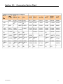
Section 10 : Conversion Factor Chart ........................................................................................................ 17
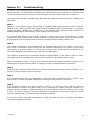
Section 11 : Troubleshooting ....................................................................................................................... 18
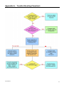
Appendix A. Trouble Shooting Flowchart .............................................................................................. 19
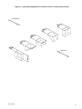
Figure 1: Typical Arrangement for Cluster of Five. Total Pressure Cells ............................................................ 21
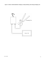
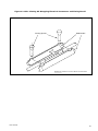
Figure 2: Stress Cell Installation Crimping of Compensating Tube Using Crimping Tool ................................... 22
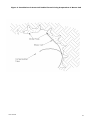
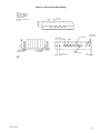
Figure 3: Installation of Stress Cell behind Tunnel Lining Preparation of Mortar Pad ......................................... 23
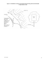
Figure 4: Installation of Stress Cell behind Tunnel Fixing Cell and Positioned Compensation Tube .................. 24
Figure 5: Preparation of Cable Joint .................................................................................................................... 25
Figure 6: Cable Jointing Kit Wrapping Electrical Connectors and Fitting Mould .................................................. 26
Figure 7: Stress Cell Slot Drilling ......................................................................................................................... 27
Figure 8: Installation of Stress Cells and Supports Prior to Grouting .................................................................. 28
User Manual
2