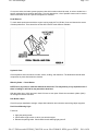
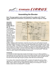
1
1997 Aerostar/Ranger
Section 06-00: Brake System, Service
DIAGNOSIS AND TESTING
Page 1 of 7
1997 Aerostar, Ranger Workshop Manual
Inspection and Verification
When it comes to today's electrically controlled RABS/4WABS, the diagnosis of many concerns requires
following the diagnostic procedures exactly as they are outlined in the service manual. But there is more to it
than that. You have to take the information given you by the customer, and combine it with your
understanding of brake systems in general. This knowledge and information will help you make the most
efficient use of the diagnostic procedures in this manual.
Getting Started
Brake system diagnosis starts with the customer's concern. It is best to get this information directly from the
customer, not just from a service write-up. Customers usually do their best to describe what they have been
experiencing and what their concerns are. But it is often necessary to ask questions and probe further in
order to get a complete picture of the problem.
Customers may report that the brake pedal (2455) went to the floor, when it actually only dropped part way.
Remember, customers get used to how their vehicle's brakes are performing. If the system suddenly
behaves differently, they may become alarmed. Under these circumstances, what they report may not be as
clearly stated as it could be. Your job is to listen carefully and ask probing questions about anything that
doesn't fit your experience and understanding of brake system functioning.
Verify the Complaint
Once you are satisfied that you understand the customer's concerns, take the vehicle on the road yourself.
Many brake concerns involve a wide variety of noises and pulsations that can only be experienced while
operating the vehicle. Make sure the vehicle's tires are inflated properly. Make your brake application
evaluation on level, dry, hard, smooth pavement that is free from oil, grease or loose dirt.
Back in the Shop
The next step in servicing a brake complaint is a thorough inspection of the system.
Brake Master Cylinder
Look for leaks. Clean the unit and remove the brake master cylinder filler cap. Check the fluid level. Check
the condition of the gasket.
Hydraulic Leaks
On vehicles with power brakes, with the engine (6007) running, apply 667 N (150 lbs.) force to the brake
pedal and hold for ten seconds. If brake pedal height cannot be maintained for 10 seconds or the brake
warning light comes on, service is required.
Occasional brake squeal can be caused by environmental conditions such as cold ambient temperatures,
heat, rain, snow, salt, mud, hot ambient temperatures or high humidity. This occasional squeal is not a
functional problem and does not indicate any loss in brake effectiveness.
Visually examine front and rear tires and wheel assemblies for damage such as uneven wear, tread
washouts, or sidewall damage. Make sure the tires are of the same size, type and, where possible, same
manufacturer. Any tire or wheel (1007) that is damaged should be replaced. Refer to Section 04-04 .
Wheels and tires must be cleared of any foreign matter, and tire pressures adjusted to the correct
file://C:\TSO\tsocache\VDTOM_5368\SVK~us~en~file=SVK60011.HTM~gen~ref.HTM
2011-04-28
1997 Aerostar/Ranger
Page 2 of 7
specification as detailed in Section 04-04 .
If tires exhibit uneven wear or feathering, the cause must be corrected. Check steering and suspension
components for damage/wear and, if necessary, check and adjust steering alignment. Refer to Section 0400 .
Road Test
A road test should be performed to compare actual vehicle braking performance with the performance
standards expected by the driver. The ability of the test driver to make valid comparisons and detect
performance deficiencies will depend on experience.
The driver should have a thorough knowledge of brake system operation and accepted general performance
guidelines, in order to make good comparisons and detect performance problems.
An experienced brake technician will always establish a route that will be used for all brake diagnosis road
tests. The road selected will be reasonably smooth and level. Gravel or bumpy roads are not suitable
because the surface does not allow the tires to grip the road equally. Crowned roads should be avoided
because of the large amount of weight shifted to the low set of wheels on this type of road. Once the route is
established and consistently used, the road surface variable can be eliminated from the test results.
A key factor in evaluating brake concerns is the deceleration rate. During braking, all of us are sensitive to
whether or not the vehicle is slowing at the rate we have come to expect. This varies from vehicle to vehicle
and with changes in operating conditions. It is evident how well the brakes on a particular vehicle are
working after just a few applications.
Stopping Distance Method
For this test, you need to mark out or find a driving lane that is 3.7m (12 ft.) wide. You also need to place two
markers along this lane, 7.5m (25 ft.) apart. At a speed of 32 km/h (20 mph), drive down the center of the
lane and apply the service brakes when you reach the first marker. Observe whether the vehicle comes to a
smooth stop before the second marker. Also note whether it pulled to the right or left and whether it went
beyond the 3.7m (12 ft.) width. For trucks under 4500 kg (10,000 lbs.) a commonly accepted standard is a
smooth stop within 7.5m (25 ft.), while staying within the lane.
Before a road test, get a complete description of the customer concerns or suspected condition. From the
description, experience will allow possible causes to be matched with symptoms. Certain components will be
tagged as possible suspects while others will be eliminated by the evidence. More importantly, the
customer's description can reveal unsafe conditions which should be checked or corrected before the road
test. The description will also help form the basic approach to the road test by narrowing the problem to
specific components, vehicle speed or conditions.
The road test should begin with a general brake performance check. With the customer's description as a
guide, the brake system should be tested at different vehicle speeds using both light and heavy brake pedal
pressure. On vehicles with rear drum brakes, to determine if the problem is in the front or rear braking
system, the service brake pedal is used first, then the parking brake. If the condition (i.e., pull, vibration,
pulsation) occurs only with the parking brake, the problem is in the rear system. If the condition occurs when
the service brake pedal is pressed, the problem is in the front system. Vehicles with rear disc brakes require
further testing to determine problem location.
Locking the brakes and sliding the tires should be avoided. Locked brakes and sliding tires do not indicate
brake efficiency: A heavily braked and turning wheel will stop the vehicle in less distance than locked
brakes. If the problem becomes evident during this check, it should be determined if it fits the description
given before the road test. If the problem is not evident, an attempt should be made to duplicate the
condition using the information from the description.
file://C:\TSO\tsocache\VDTOM_5368\SVK~us~en~file=SVK60011.HTM~gen~ref.HTM
2011-04-28
1997 Aerostar/Ranger
Page 3 of 7
If a concern exists, the brake system symptom chart in this section should be used, in order to isolate it to a
specific subsystem and condition description. From this description, a list of possible causes can be used to
further narrow the cause to a specific component or condition.
Pedal Reserve
To check brake pedal reserve with the engine running, apply 667 N (150 lbs.) force and observe the extent
of brake pedal travel. There should be at least 20% reserve travel distance available.
Hydraulic Parts
Check hydraulic hoses and tubes for leaks, cracks, chafing, and distortions. The fasteners that hold these
components in place should also be checked.
Wheel Cylinder — Drum Brakes
NOTE: Don't pry under or otherwise disturb the dust boot. This may destroy a very important seal. If
there is leakage, it will find its way around the dust boot.
With the brake drum (1126) removed, check for loose or worn parts. Check the rear wheel cylinder (2261)
for leakage around the dust boot.
Disc Brake Caliper
Check for proper installation, leakage, caliper slide lubrication and excessive wear along caliper supports.
Dual Circuit Warning Light
Functions:
Apply the parking brake.
Check that the light comes on when you start the engine.
Release the parking brake. Check that the brake warning light goes off.
file://C:\TSO\tsocache\VDTOM_5368\SVK~us~en~file=SVK60011.HTM~gen~ref.HTM
2011-04-28
1997 Aerostar/Ranger
Page 4 of 7
Detecting Causes of Brake Problems
ABS brake systems, with their electronically-controlled components, provide a greater degree of braking
control than ever before. The fault codes generated by the built-in diagnostics make solving many concerns
a simple matter. However, it isn't always possible to immediately nail the culprit when something isn't
working properly. Eliminate the obvious first, and gradually close in on the real concern.
Start with the clues found during basic inspection. Correct the obvious problems and see how that affects
the performance of the system. Save the potentially difficult possibilities for last. Many times, the concern will
be corrected before you have to get into more challenging areas.
The most difficult concerns are often intermittent. Make sure the problem is really an intermittent brake issue
and not an intermittent operating condition. Get as much information as possible.
Talk to the primary driver. Find out how often it actually happens, what time of day, what the load is, what
the road conditions are and what the weather is like. Listen carefully. There may be important clues in the
answers.
Isolating ABS
WARNING: DO NOT DISABLE THE FRONT BRAKES. IF YOU DO, STOPPING DISTANCES MAY
BE EXTREMELY LONG, ESPECIALLY IN VEHICLES THAT ARE UNLOADED.
Many concerns that seem at first to be ABS related are actually problems with the base brake system. On
the rear anti-lock systems (RABS) pull the brake fluid level sensor connector and fasten it safely out of the
way. This will effectively disable the RABS, but leave the normal power assisted brake system functioning
normally.
Road test the vehicle. With RABS disabled, you will get a good feel for the functioning of the base brake
system and any concerns. Fix these concerns before testing the ABS itself.
This procedure will demonstrate the vehicle's deceleration before lockup. This will help evaluate the vehicle's
braking performance after correcting all concerns. Use one of the deceleration tests referred to earlier for
accurate measure of the deceleration rate.
With the RABS disconnected, test for brake imbalance. Apply pressure quickly to detect one wheel locking
up before the other. With RABS functioning, this judgment can't be made.
Reactivate the RABS to check for the pedal pulsation. Remember that the RABS shuts off below
approximately 8 km/h (5 mph), which can result in lockup at the conclusion of a stop. Operate vehicle safely
to reach speed when testing.
Premature RABS Activation
One concern that may be a challenge to isolate is premature RABS activation. The first step is to thoroughly
check out the base brake system. If the base brake system checks out and there is still premature RABS
activation, there are several areas to take a close look at:
A weak sensor signal: Look for a bad wheel speed sensor, chips on the pole piece or an air gap
that's too high.
A wiring problem: Look for chafed wires that might be causing a faulty electrical circuit.
A rear axle problem: Rear axle malfunctions account for many premature RABS activation
file://C:\TSO\tsocache\VDTOM_5368\SVK~us~en~file=SVK60011.HTM~gen~ref.HTM
2011-04-28
1997 Aerostar/Ranger
Page 5 of 7
problems. Look for rear axle speed sensor ring damage and for play in the differential that allows the
rear axle speed sensor ring to move away from the wheel speed sensor.
The "Rolling Skid"
NOTE: Some initial, momentary wheel lockup is permissible during this test.
ABS are designed to sense the RAPID deceleration rate of a wheel. This is what warns of possible lockup.
Some tires have high peak traction which tends to fall off rapidly. When a tire has this characteristic, the
ABS can easily perform as designed. When increasing the braking force, the tires rapidly decelerate, and at
the appropriate point, the ABS kicks in at the wheel or axle that needs reduced pressure. Brake pedal
pulsations can be felt, and on 4WABS the pump motor can be heard.
Tires with a tendency to develop peak traction which then falls off more slowly may slip some as they
decelerate (sometimes referred to as a "rolling skid"). This was a typical characteristic of bias belted tires.
This condition may cause the ABS system not to activate, because the wheel isn't fully locking up. There
may, however, be considerable squealing and smoking of the tires, and sometimes even skid marks. This is
a concern the customer may report.
Have the customer take you for a drive to demonstrate. Observe how the driver activates the brakes. Before
beginning the test, adjust the outside rearview mirrors so you can observe the rear wheels.
Have the owner apply the brakes normally during a hard stop. Ford recommends speeds of no more than 24
km/h (15 mph) for this test. If you feel the ABS activate, rolling skid isn't the problem.
If the ABS doesn't activate, have the driver increase the pressure until they squeal and smoke. Hold in this
position. Observe rearview mirrors for evidence of smoke. It is also helpful to have an assistant standing
nearby who can watch the wheels from a better angle during the test.
Check to see if the wheels continue to rotate for the duration of the stop.
Finally, see if increasing the pressure even more will cause the ABS to activate. If it does, the vehicle is
experiencing the slow drop-off from peak traction discussed above.
This last step, applying extra pressure, is very important to the diagnosis. Many drivers back off on the
brakes when they hear the squeal because they think, and understandably so, that a wheel or wheels are
locking up. Correcting this problem may mean explaining that the system is functioning fine and the wheels
are not locking up.
RABS and 4-Wheel Drive
When diagnosing RABS concerns on a 4-wheel drive vehicle, remember that the front and rear drivetrains
are mechanically locked together in 4-wheel drive. If the front wheels turn, the rear wheels turn. If the front
wheels lock up, the rear wheels lock up. The RABS can't prevent lockup in the rear when the front brakes
are applied hard enough to cause lockup on low-traction surfaces.
For more information on the rear anti-lock brake system (RABS), refer to Section 06-09A . For more
information on the four wheel anti-lock brake system (4WABS), refer to Section 06-09B .
The Vehicle That Keeps Coming Back
If you get a vehicle that has been brought in for brake service frequently, take a close look at the service
history. How long did that vehicle go before its first brake service? What has happened since? If
components have been replaced, are they the correct parts? Recurring problems can be the result of some
mistake made earlier in the service history.
file://C:\TSO\tsocache\VDTOM_5368\SVK~us~en~file=SVK60011.HTM~gen~ref.HTM
2011-04-28
1997 Aerostar/Ranger
Page 6 of 7
Brake Pedal Feel and Stopping Distance
A combination of things indicates whether brakes are working properly: The feel of the brake pedal, how
rapidly the vehicle slows down and distance travelled before stopping. If the brakes are working properly and
we experience the expected feel and results, we are confident. If the brakes feel different and/or the vehicle
doesn't slow or stop as expected, we feel uneasy. . .even panicked. This panic will be heightened in
emergency stopping situations.
Customers often report brake problems in terms of brake pedal feel. "My brakes feel spongy" or "The brake
pedal went to the floor" or "The brakes feel hard and I have to apply much more force than usual" are all
possible customer complaints. These complaints are often accompanied by reports that the vehicle "Just
didn't stop the way it should." These simple complaints may indicate problems that are much more complex
to diagnose and correct.
What makes understanding brake feel and stopping distance a challenge is that different brake systems
have a different feel and a different braking response. Feel is the result of several factors:
Stopping Perceptions
Design
Brake feel will vary from vehicle to vehicle, even of the same design depending on how the vehicle is
equipped.
Operation
How the vehicle is used may also change the feel of the brakes. Factors such as loading, trailer towing and
operating on steep grades or gravel roads can all affect the feel of the brakes.
Pedal Force and Travel
file://C:\TSO\tsocache\VDTOM_5368\SVK~us~en~file=SVK60011.HTM~gen~ref.HTM
2011-04-28
1997 Aerostar/Ranger
Page 7 of 7
The amount of force applied, combined with the amount of brake pedal travel will affect the feel and stopping
response. Some drivers are stronger than others and can force the brake pedal down further.
Spring or Give in the System
This is a very important concept. A braking system isn't rigid. Every part has some give. For example, the
disc brake calipers (2B120) flex a little as force is applied, flexible hoses swell a little under pressure, and
shoe return springs are extended. The combination of these and other points where the system gives a little
results in a "springiness" that "fights back" against the hydraulic pressure. This "fighting back" is felt through
the brake pedal. As parts of the system become worn or corroded, this "fighting back" feel may change.
file://C:\TSO\tsocache\VDTOM_5368\SVK~us~en~file=SVK60011.HTM~gen~ref.HTM
2011-04-28
1997 Aerostar/Ranger
Page 1 of 9
Section 06-00: Brake System, Service
DIAGNOSIS AND TESTING
1997 Aerostar, Ranger Workshop Manual
Symptom Chart — Brake System Service
BRAKE SYSTEM SERVICE
Condition
Brakes Not
Working,
Excessive Pedal
Travel, Brake
Pedal Feels
Spongy When
Fully Applied
Possible Source
Action
Low fluid level.
ADD fluid, BLEED
system, CHECK for
leaks, and BLEED
system.
Worn or damaged four wheel ABS
hydraulic control unit (Ranger only).
REFER to Section 0609B , Symptom Chart.
Worn or damaged RABS valve
accumulator or outlet (dump) valve
REFER to Section 0609A , Symptom Chart.
Rear brakes out of adjustment.
ADJUST rear brakes.
REFER to Section 0602 .
Front wheel bearing out of adjustment.
ADJUST front wheel
bearings. REFER to
Section 04-01A for all
4x2 vehicles, Section
05-03A for Ranger
and Section 04-01C
for Aerostar 4x4.
Brake master cylinder or booster dash
unit mounting loose.
TIGHTEN nuts and
bolts to specification.
Disc brake caliper attachment loose.
REPLACE or
TIGHTEN as required.
Worn or damaged brake shoe adjusting
lever cables .
REMOVE drum and
CHECK lining for
proper adjustment.
REPLACE brake shoe
adjusting lever cables.
REFER to Section 0602 .
Glazed, worn, scored or damaged
brake linings.
REPLACE rear brake
shoes and linings.
REFER to Section 0602 .
Drums out of round or rotors with
excessive runout.
REFINISH, or
REPLACE if wear
exceeds limits.
REFER to Section 0603 , Section 06-02 .
Front brake hose improperly positioned.
CHECK front brake
file://C:\TSO\tsocache\VDTOM_5368\SVK~us~en~file=SVK60012.HTM~gen~ref.HTM
2011-04-28
1997 Aerostar/Ranger
Page 2 of 9
hose for misposition
near heat source.
REPOSITION as
required.
Excessive Pedal
Travel or Brake
Pedal Goes to
Floor
Consistently
Excessive Pedal
Effort to Fully
Apply Brakes
Air in system.
BLEED system.
REFER to Section 0606 .
Reservoir cap vent hole clogged.
SERVICE or
REPLACE brake
master cylinder filler
cap as required.
Hydraulic system.
PERFORM master
cylinder diagnosis
test. REFER to
Pinpoint Test R and
Pinpoint Test T .
REPAIR as required.
Brake drums worn, bad wear pattern, or
cracked.
REPAIR or REPLACE
as required. REFER
to Section 06-02 .
Loose or improper attachment of brake
pedal, pedal support booster and brake
master cylinder.
REPAIR or REPLACE
as required. REFER
to Section 06-07 .
External leak.
REPAIR as required.
Air in system.
BLEED system.
REFER to Section 0606 .
Overloaded vehicle.
LIGHTEN load and
ADVISE owner of
correct load limits of
vehicle.
Insufficient vacuum to power brake
booster.
REPLACE damaged
or leaking vacuum
booster hoses.
Restricted air filter on power brake
booster.
CLEAN or REPLACE
filter.
Booster and brake pedal linkage
binding caused by worn bushings or
corrosion.
REPLACE worn
bushings or CLEAN
and LUBRICANT
linkage.
Worn or damaged power brake booster.
REPLACE power
brake booster.
REFER to Section 0607 .
Brake lining worn, glazed, contaminated
or improper type.
REPLACE brake
lining in axle sets.
Rear brake shoe and lining improperly
installed.
REPOSITION brake
shoes properly and
ELIMINATE any
binding. REFER to
Section 06-02 .
file://C:\TSO\tsocache\VDTOM_5368\SVK~us~en~file=SVK60012.HTM~gen~ref.HTM
2011-04-28
1997 Aerostar/Ranger
Brakes Drag,
Slow or
Incomplete
Release
Empty Reservoir
Noise at Wheels
When Brakes
Are Applied —
Snap or Clicks
Page 3 of 9
Seized caliper pistons in rear wheel
cylinders or disc brake calipers.
REPAIR or REPLACE
as required.
Restricted brake lines or hoses.
REPAIR or REPLACE
as required.
Parking brake control or parking brake
rear cable and conduits binding.
REPAIR,
LUBRICATE, or
REPLACE parts as
required. REFER to
Section 06-05 .
Rear brake components binding.
REPAIR,
LUBRICATE, or
REPLACE parts as
required.
Damaged front wheel bearing.
CHECK bearings for
adjustment, wear,
damage. ADJUST
bearings.
Worn or damaged brake master
cylinder.
PERFORM master
cylinder diagnosis
test. REFER to
Pinpoint Test R and
Pinpoint Test T .
REPAIR as required.
Caliper slides binding.
REPLACE slide pins,
CLEAN grooves,
LUBRICATE slides.
Brakes out of adjustment.
ADJUST rear brakes.
REFER to Section 0602 .
Restriction in hydraulic system.
REPAIR or REPLACE
as required. REFER
to Section 06-06 .
Binding/seized rear wheel cylinders or
caliper pistons.
REPAIR or REPLACE
as required. REFER
to Section 06-03 , or
Section 06-02 .
Damaged brake master cylinder
reservoir.
REPLACE brake
master cylinder
reservoir. REFER to
Section 06-06 .
Leaking mounting grommets.
REPLACE grommets
and brake master
cylinder reservoir.
Leaking components (lines, hoses, disc
brake calipers, rear wheel cylinder,
etc.).
REPAIR as required.
BLEED system as
required.
Cracked welds at brake shoe web.
REPLACE rear brake
shoe and lining in axle
sets.
file://C:\TSO\tsocache\VDTOM_5368\SVK~us~en~file=SVK60012.HTM~gen~ref.HTM
2011-04-28
1997 Aerostar/Ranger
Noise at Wheels
When Brakes
Are Applied —
Scrape or Grind
Noise at Wheels
When Brakes
Are Applied —
Squeaks,
Squeals or
Chatter
Page 4 of 9
Brake shoes binding at backing plate
ledges.
CLEAN and
LUBRICATE ledges.
Machining marks on brake drums.
REFINISH, or
REPLACE brake
drums. REFER to
Section 06-02 .
Backing plate ledges worn.
REPLACE brake
backing plate and
LUBRICATE ledges.
REFER to Section 0602 .
Loose or missing disc brake pad antirattle clips.
REPLACE. REFER to
Section 06-03 .
Improper rotor finish after turning.
REFINISH or
REPLACE disc brake
rotors. REFER to
Section 06-03 .
Improper positioning, wear or damage
of disc brake caliper.
INSPECT, REPAIR or
REPLACE. REFER to
Section 06-03 .
Worn brake linings, loose rivets or
foreign material scraping brake
components.
REPLACE rear brake
shoes and linings.
REFINISH or
REPLACE brake
drums or disc brake
rotors if excessively
scored. REFER to
Section 06-03 ,
Section 06-02 .
Brake shoe interference with back of
brake drum, shield-to-rotor clearance or
binding at backing plate guide ledges.
INSPECT. REPLACE
as necessary.
LUBRICATE. REFER
to Section 06-02 ,
Section 06-03 .
Other brake system components.
Warped or bent brake backing
plate causing interference with
brake drum.Cracked brake
drums or disc brake rotors.Loose
brake shoe hold-down springs.
INSPECT and
REPAIR as
necessary. REFER to
Section 06-02 ,
Section 06-03 .
Tires rubbing against chassis, body, or
loose brake shoe hold-down springs.
INSPECT. REPAIR as
necessary. REFER to
Section 04-04 .
Worn or scored brake drums and lining
or disc brake rotors.
INSPECT, REPAIR or
REPLACE as
required. REFER to
Section 06-03 , or
Section 06-02 .
Burrs or rust on disc brake caliper that
would obstruct seating of shoe to disc
brake caliper.
CLEAN or DEBURR
disc brake caliper.
file://C:\TSO\tsocache\VDTOM_5368\SVK~us~en~file=SVK60012.HTM~gen~ref.HTM
2011-04-28
1997 Aerostar/Ranger
Noise at
Wheels, Brakes
Not Applied —
Squeak or
Squeal
Noise at
Wheels, Brakes
Not Applied —
Growling, Click
or Rattle
Page 5 of 9
Dirty, greased or glazed linings.
CLEAN or REPLACE.
Improper lining parts or loose rear
brake adjustment.
INSPECT for correct
usage. If necessary
REPLACE with
correct type in axle
sets. REFER to
Section 06-02 ,
Section 06-03 .
Other brake system components.Loose
lining rivets.Weak, damaged or
incorrect brake shoe retracting
springs.Loose or damaged shoe
retaining pins, brake shoe retracting
springs and clips.Grooved backing plate
ledges.
INSPECT, REPAIR or
REPLACE as
required. REFER to
Section 06-02 .
Wheel covers improperly attached.
SEAT covers with a
rubber mallet.
REPAIR flanges or
REPLACE cover.
Loose wheel attaching lug nuts.
TIGHTEN to proper
torque. REPLACE
wheel if stud holes
are damaged.
Worn, dry or improperly adjusted wheel
bearings.
REPLACE worn or
damaged wheel
bearings.
LUBRICATE and
ADJUST.
Glazed linings — adjustment too tight.
REMOVE glaze from
linings. ADJUST
brakes properly.
Other brake system
components.Stretched brake shoe
retracting springs.Bent or warped brake
backing plate causing interference with
brake drum.Improper positioning of disc
brake pad in disc brake
caliper.Excessive runout of front disc
brake rotor.
INSPECT, REPAIR or
REPLACE as
required. REFER to
Section 06-02 , or
Section 06-03 as
required.
Stones or foreign material trapped
inside wheelcovers.
REMOVE stones, etc.
Loose wheel lug nuts.
TIGHTEN to correct
torque. REPLACE
wheel if stud holes
are elongated.
REFER to Section 0404 .
Damaged, worn, or improperly adjusted
wheel bearings.
ADJUST or
REPLACE as
file://C:\TSO\tsocache\VDTOM_5368\SVK~us~en~file=SVK60012.HTM~gen~ref.HTM
2011-04-28
1997 Aerostar/Ranger
Page 6 of 9
required.
Noise at
Wheels, Brakes
Not Applied —
Squeaks,
Squeals or
Chatter
Loose or missing anti-rattle clips, or
caliper pins.
INSPECT, REPAIR or
REPLACE as
required. REFER to
Section 06-03 .
Drum brake linings/shoes loose or extra
parts.
INSPECT, REMOVE
or REPAIR. REFER to
Section 06-02 .
Worn, damaged or dry wheel bearings.
INSPECT,
LUBRICATE or
REPLACE. ADJUST
bearings properly.
Grinding Noise
Improperly lubricated wheel bearings.
SERVICE as
required. REFER to
Section 04-01A for
4x2 and Section 0503A for Ranger, and
Section 04-01C for
Aerostar 4x4.
Excessive Brake
Lining Wear
Improperly adjusted wheel bearings.
ADJUST or
REPLACE as
required. REFER to
Section 04-01A for
4x2 and Section 0503A for Ranger.
Binding caliper sliders.
SERVICE as
required.
Improperly adjusted wheel bearings.
ADJUST or
REPLACE as
required. REFER to
Section 04-01A for
4x2, Section 05-03A
for Ranger and
Section 04-01C for
Aerostar 4x4.
Excessive rotor runout, or thickness
variation.
SERVICE or
REPLACE as
required.
Loose wheel lug nuts.
TIGHTEN to correct
torque. REPLACE
wheel if stud holes
are elongated.
REFER to Section 0404 .
Worn, damaged, dry or improperly
adjusted wheel bearings.
INSPECT,
LUBRICATE or
REPLACE.
Loose or worn front suspension
components.
INSPECT, REPAIR or
REPLACE as
required. REFER to
Brake
Roughness,
Vibration or
Pulsation
Groan,
Roughness or
Chatter at
Wheel (Brakes
Applied)
file://C:\TSO\tsocache\VDTOM_5368\SVK~us~en~file=SVK60012.HTM~gen~ref.HTM
2011-04-28
1997 Aerostar/Ranger
Page 7 of 9
Section 04-00 .
Brakes Pull to
One Side
Brakes Grab or
Lock When
Applied
Brake drum cracked or out of round.
REPLACE drum if
required. REFER to
Section 06-02 .
Disc brake caliper loose, or missing
parts — also loose or bent dust shield.
REPAIR or REPLACE
as required. REFER
to Section 06-03 .
Excessive wear or lateral runout of disc
brake rotor.
REPLACE rotor.
REFER to Section 0603 .
Worn tires.
REPLACE tires.
REFER to Section 0404 .
Unequal air pressure in tires.
INFLATE tires to
correct pressure.
Grease or fluid on linings. Glazed
linings.
CLEAN, SAND or
REPLACE linings.
CLEAN disc brake
rotors.
Loose or missing disc brake caliper pin.
REPLACE missing
pin. REFER to
Section 06-03 .
Improper size or type of lining on one
wheel.
REPLACE with
correct brake linings
in sets.
Improper size wheel cylinder on one
wheel.
REPLACE with
correct wheel
cylinder. REFER to
Section 06-02 .
Stuck or seized pistons in wheel
cylinders or seized calipers.
REPAIR or REPLACE
as required. REFER
to Section 06-03 , or
Section 06-02 .
Restricted brake lines or hoses.
REPAIR or REPLACE
as required.
Other brake components.Improper
adjustment of drum brakes.Improper
positioning of disc brake shoe and lining
in the caliper.Fit of caliper to
knuckle.Improperly adjusted, damaged
or worn wheel bearings.Distorted drum
brake shoes.Worn brake linings or
scored rotor.Missing, broken or
stretched retracting or retaining springs
and clips.
INSPECT, ADJUST,
REPAIR or REPLACE
as required. REFER
to Section 06-02 or
Section 06-03 .
Suspension or steering.
REPAIR as required.
Tires worn or incorrect pressure.
INFLATE tires to
correct pressure.
REPLACE tires with
worn tread. REFER to
Section 04-04 .
file://C:\TSO\tsocache\VDTOM_5368\SVK~us~en~file=SVK60012.HTM~gen~ref.HTM
2011-04-28
1997 Aerostar/Ranger
Brake Warning
Light On
Vibration When
Brakes Are
Applied.
Page 8 of 9
Grease or fluid on linings — damaged
linings.
REPLACE lining in
sets. CLEAN rotors.
Improper size or type of linings.
REPLACE with
correct brake linings
in sets.
Over-reaction of brake booster.
REPLACE brake
booster if required.
REFER to Section 0607 .
Lining sensitivity to moisture.
DRY linings by
applying brakes while
moving.
Other brake system components.Loose
or missing pins for caliper
attachment.Worn, damaged or dry
wheel bearings.
INSPECT, REPAIR,
REPLACE or
LUBRICATE if
required. REFER to
Section 06-03 , or
Section 06-02 .
ABS HCU: defective outlet (dump)
valve Ranger 4x4.
REFER to Section 0609B .
RABS Valve: defective outlet (dump)
valve.
REFER to Section 0609A .
Low brake fluid level.
ADD fluid, CHECK for
leaks, and BLEED
system as required.
Parking brake applied or not returning
completely.
RELEASE parking
brake.
Shorted light circuit.
CORRECT short in
brake warning light
circuit.
Damaged fluid level switch or float
assembly.
REPLACE plastic
brake master cylinder
reservoir.
Differential pressure switch shuttled
(Aerostar only) due to leakage in
hydraulic circuit or damaged differential
switch.
REPAIR leakage in
hydraulic circuit or
REPLACE
combination valve.
Anti-lock light does self check.
REFER to Diagnostic
Charts in Section 0609A or Section 0609B .
Loose lug nuts.
TIGHTEN lugnuts to
specification.
REPLACE rim if stud
holes are elongated.
REFER to Section 0404 .
Cracked disc brake rotors.
REPLACE front disc
brake rotor. REFER to
Section 06-03 .
file://C:\TSO\tsocache\VDTOM_5368\SVK~us~en~file=SVK60012.HTM~gen~ref.HTM
2011-04-28
1997 Aerostar/Ranger
Page 9 of 9
Front disc brake rotors/brake drums out
of round or improper machining.
MACHINE disc brake
rotors or brake drums
or REPLACE as
required.
Worn or improperly adjusted wheel
bearings.
ADJUST or
REPLACE wheel
bearings as required.
Loose or worn front suspension
components.
TIGHTEN loose
components to
specifications.
REPLACE worn or
damaged
components.
Excessive radial or lateral runout on
wheel and tire.
ADJUST or
REPLACE tire or
wheel to ELIMINATE
excessive runout on
tire or wheel as
required. REFER to
Section 04-04 .
file://C:\TSO\tsocache\VDTOM_5368\SVK~us~en~file=SVK60012.HTM~gen~ref.HTM
2011-04-28
1997 Aerostar/Ranger
Page 1 of 18
Section 06-00: Brake System, Service
DIAGNOSIS AND TESTING
1997 Aerostar, Ranger Workshop Manual
Pinpoint Tests
DIAGNOSTIC PINPOINT TEST INDEX
Description
Test
Brakes Pull or Drift
Test A
Brake Warning Indicator Always On
Test B
Vibration When Brakes Are Applied
Test C
Pedal Goes Down Fast
Test D
Pedal Goes Down Slowly
Test E
Pedal Is Low or Feels Spongy
Test F
Brake Lockup During Light Brake Pedal Force
Test G
Excessive and/or Erratic Pedal Travel
Test H
Brakes Drag
Test J
Brakes Shudder
Test K
Brake Pedal Excessive Effort, Booster System OK
Test L
Brake Noise
Test M
Slow or Incomplete Brake Pedal Return
Test N
Vibration, Pedal Pumping, Low Pedal or Brake Chatter
Test P
Hydraulic Leak Test
Test Q
Brake Master Cylinder Bypass Condition Check
Test R
Excessive Pedal Effort
Test S
Brake Fluid Loss, Brake Master Cylinder Internal Test OK Test T
PINPOINT TEST A: BRAKES PULL OR DRIFT
A1 INSPECT TIRE PRESSURE
Measure air pressure in all four tires.
Is tire pressure within specifications?
Yes
GO to A2 .
No
ADJUST tire pressure.
file://C:\TSO\tsocache\VDTOM_5368\SVK~us~en~file=SVK60013.HTM~gen~ref.HTM
2011-04-28
1997 Aerostar/Ranger
Page 2 of 18
A2 CHECK CALIPER AND REAR WHEEL CYLINDERS
Check the front disc brake caliper pistons, pins or rear wheel cylinders for binding, leakage or
sticking.
Do the front disc brake caliper pistons, pins or rear wheel cylinders bind or stick?
Yes
REPAIR or REPLACE components as
necessary.
No
GO to A3 .
A3 INSPECT FRONT DISC BRAKE ROTORS AND BRAKE DRUMS
Inspect the disc brake rotors and/or brake drums for excessive runout or damage.
Does excessive runout or damage exist?
Yes
REPAIR or REPLACE disc brake rotor or brake
drum as necessary.
No
GO to A4 .
A4 INSPECT WHEEL BEARINGS
Inspect front and rear wheel bearings for excessive end play or improper preload.
Does excessive end play or improper wheel bearing preload exist?
Yes
ADJUST wheel bearing preload or REPLACE
wheel bearings.
No
INSPECT for and REPAIR hydraulic leaks.
RETEST system.
PINPOINT TEST B: BRAKE WARNING INDICATOR ALWAYS ON
B1 CHECK PARKING BRAKE SWITCH
With parking brake fully released, disconnect the parking brake switch C202 (Ranger) or C309
(Aerostar).
Did brake warning indicator light go out?
Yes
REPLACE the parking brake switch. RETEST.
No
GO to B2 .
file://C:\TSO\tsocache\VDTOM_5368\SVK~us~en~file=SVK60013.HTM~gen~ref.HTM
2011-04-28
1997 Aerostar/Ranger
Page 3 of 18
B2 ISOLATE CIRCUITS, 531 (DG/R), 977 (P/W), AND 162 (LG/R)
With brake master cylinder reservoir fluid level OK, disconnect the brake master cylinder fluid level
switch C137 (Ranger) or C165 (Aerostar).
Does the brake warning indicator light go out?
Yes
No
SERVICE ground short in Circuit 531 (DG/Y),
977 (P/W), or 162 (LG/R).
GO to B3 .
B3 TEST BRAKE FLUID LEVEL INDICATOR SWITCH
Test for continuity between fluid level switch C137 (Ranger) or C165 (Aerostar), circuit 512 (T/LG)
and ground .
Is there 10,000 ohms or more?
Yes
REPLACE the brake master cylinder reservoir.
No
SERVICE short to ground in Circuit 512 (T/LG).
PINPOINT TEST C: VIBRATION WHEN BRAKES ARE APPLIED
C1 ISOLATE VIBRATION/SHUDDER
Determine if vibration/shudder is induced by the rear brakes by using the parking brake to slow the
vehicle from approximately 80 to 56 km/h (50 to 35 mph). To use the parking brake:
Hold the release handle out, or press release button in, while applying the parking brake.
Is vibration/shudder present?
Yes
CHECK the rear brakes. GO to C2 for disc
brakes. GO to C3 for drum brakes.
No
CHECK the front brakes. GO to C2 .
C2 RESURFACE DISC BRAKES
Resurface front disc brake rotors and road test vehicle.
Is shudder/vibration present?
Yes
GO to C4 .
No
Brake system repaired.
file://C:\TSO\tsocache\VDTOM_5368\SVK~us~en~file=SVK60013.HTM~gen~ref.HTM
2011-04-28
1997 Aerostar/Ranger
Page 4 of 18
C3 REFINISH BRAKE DRUMS
Refinish brake drums and road test vehicle.
Is shudder/vibration present?
Yes
GO to C5 .
No
Brake system repaired.
C4 REPLACE DISC BRAKE PADS
Replace disc brake pads and road test vehicle.
Is shudder/vibration present?
Yes
REPLACE front disc brake rotors.
No
Brake system repaired.
C5 REPLACE BRAKE SHOES AND LININGS
Replace rear brake shoes and linings and road test vehicle.
Is shudder/vibration present?
Yes
DETERMINE which brake drum is at fault and
REPLACE.
No
Brake system repaired.
PINPOINT TEST D: PEDAL GOES DOWN FAST
D1 ROAD TEST
Road test vehicle only if condition cannot be verified in shop.
Statically depress brake pedal.
Does brake pedal operate properly?
Yes
Vehicle OK.
No
GO to D2 .
file://C:\TSO\tsocache\VDTOM_5368\SVK~us~en~file=SVK60013.HTM~gen~ref.HTM
2011-04-28
1997 Aerostar/Ranger
Page 5 of 18
D2 CHECK BRAKE FLUID LEVEL
Check brake fluid level.
Is fluid level within specifications?
Yes
No
CHECK reservoir sealing points. ADD fluid and
BLEED system. REPEAT Test D1 .
GO to D3 .
D3 PRESSURIZE SYSTEM
Pump brake pedal rapidly (five times).
Does brake pedal maintain height throughout test?
Yes
CHECK rear brake adjustment and ADJUST if
necessary. If condition still exists, BLEED
system. REPEAT Test D1 .
No
GO to D4 .
D4 INSPECT FOR BRAKE SYSTEM LEAKS
Perform Hydraulic Leak Test — Pinpoint Test Q in this section.
Does system leak?
Yes
SERVICE as necessary. ADD fluid and BLEED
system. REPEAT Test D1 .
No
GO to D5 .
D5 BRAKE MASTER CYLINDER BYPASS TEST
Perform Brake Master Cylinder Bypass Condition Check — Pinpoint Test R in this section.
Is test OK?
Yes
System OK.
No
REPLACE damaged parts. ADD fluid and
BLEED system. REPEAT Test D1 .
PINPOINT TEST E: PEDAL GOES DOWN SLOWLY
file://C:\TSO\tsocache\VDTOM_5368\SVK~us~en~file=SVK60013.HTM~gen~ref.HTM
2011-04-28
1997 Aerostar/Ranger
Page 6 of 18
E1 ROAD TEST
Check if condition occurs during actual stopping application by depressing the brake pedal while the
vehicle is moving.
Does condition occur when vehicle is moving?
Yes
No
Condition occurs only when vehicle is
stationary. Normal condition. No action required.
GO to E2 .
E2 RECHECK BRAKE SYSTEM LEAKS
Perform Hydraulic Leak Test — Pinpoint Test Q in this section.
Does system leak?
Yes
SERVICE as necessary, ADD fluid and BLEED
system. REPEAT Test E1 .
No
GO to E3 .
E3 MASTER CYLINDER BYPASS TEST
Perform Brake Master Cylinder Bypass Condition Check — Pinpoint Test R in this section.
Is test OK?
Yes
No
REPLACE damaged parts, ADD fluid and
BLEED system. REPEAT Test E1 .
System OK.
PINPOINT TEST F: PEDAL IS LOW OR FEELS SPONGY
F1 BRAKE PEDAL CHECK
Statically apply brake pedal.
Road test vehicle only if condition cannot be verified in shop.
Does brake pedal operate properly?
Yes
Vehicle OK.
No
GO to F2 .
file://C:\TSO\tsocache\VDTOM_5368\SVK~us~en~file=SVK60013.HTM~gen~ref.HTM
2011-04-28
1997 Aerostar/Ranger
Page 7 of 18
F2 BRAKE PEDAL RESERVE CHECK
Key ON, engine running at idle with transmission in PARK or NEUTRAL.
Depress brake pedal lightly three or four times.
Wait 15 seconds to allow the vacuum to replenish.
Push down on brake pedal until it stops moving downward or an increased resistance to the brake
pedal travel occurs.
NOTE: This increased resistance may feel like the pedal has bottomed out.
Hold the brake pedal in the applied position while increasing the engine speed to 2000 rpm.
Release the accelerator pedal.
Does the brake pedal move downward as engine speed returns to normal?
Yes
No
CHECK vacuum to power brake booster.
REFER to Section 06-07 .
GO to F3 .
F3 BRAKE FLUID LEVEL CHECK
Check brake fluid level.
Is brake fluid level within specifications?
Yes
No
CHECK brake master cylinder reservoir sealing
points. ADD fluid and BLEED system.
GO to F4 .
F4 FILLER CAP VENT CHECK
Check if brake master cylinder filler cap vent holes are clogged or dirty.
Are holes clogged or dirty?
Yes
CLEAN as necessary. REPEAT Test F1 .
No
GO to F5 .
F5 BLEED BRAKE SYSTEM
Bleed brake system. Refer to Section 06-06 .
Has the condition been corrected?
Yes
No
file://C:\TSO\tsocache\VDTOM_5368\SVK~us~en~file=SVK60013.HTM~gen~ref.HTM
2011-04-28
1997 Aerostar/Ranger
Page 8 of 18
Vehicle OK.
GO to F6 .
F6 FRONT WHEEL BEARING ADJUSTMENT
Check front wheel bearings for proper adjustment.
Are bearings properly adjusted?
Yes
CHECK rear brake adjustment and ADJUST if
necessary. REPEAT Test F1 .
No
ADJUST front wheel bearings. REPEAT Test
F1 .
PINPOINT TEST G: BRAKE LOCKUP DURING LIGHT BRAKE PEDAL FORCE
G1 TIRE CHECK
Check tires for uneven wear and correct pressure.
Is there a wear or pressure concern?
Yes
CORRECT tire concern. REFER to Section 0404 .
No
GO to G2 .
G2 BRAKE SHOE AND LINING CHECK
Inspect brake shoe and linings for contamination, correct installation, damage, correct size and type.
Is there a brake shoe and lining concern?
Yes
REPAIR or REPLACE brake shoe and lining.
REFER to Section 06-02 , Section 06-03 .
No
GO to G3 .
G3 PARKING BRAKE CHECK
Inspect parking brake components for damage or seized condition.
Is there a parking brake concern?
Yes
No
file://C:\TSO\tsocache\VDTOM_5368\SVK~us~en~file=SVK60013.HTM~gen~ref.HTM
2011-04-28
1997 Aerostar/Ranger
Page 9 of 18
CORRECT parking brake concern. REFER to
Section 06-05 .
GO to G4 .
G4 WHEEL BEARING CHECK
Raise vehicle enough to relieve weight on tires.
Pull alternately on front and rear of each tire to check for loose or damaged wheel bearings.
Is there a wheel bearing concern?
Yes
CORRECT the wheel bearing concern. REFER
to the appropriate section in Group 04 or
Section 05.
No
GO to G5 .
G5 POWER BRAKE BOOSTER PUSH ROD CHECK
Support the brake master cylinder and remove the brake master cylinder mounting nuts.
Position the brake master cylinder out of the way.
With a shop-fabricated gauge, check the power brake booster push rod adjustment.
The exposed end of the power brake booster push rod should be within 24.89-25.27mm (0.980-0.995
in.) of the brake master cylinder mounting surface on the power brake booster.
Does the power brake booster push rod require adjustment?
Yes
ADJUST as necessary. REFER to Section 0607 .
No
GO to G6 .
G6 ABS CHECK
Perform the appropriate diagnostic tests in Section 06-09A or Section 06-09B to check for defective
dump valve.
Is there an anti-lock brake system concern?
Yes
REPAIR or REPLACE the worn or damaged
anti-lock brake system component. REFER to
Section 06-09A or Section 06-09B .
No
To CHECK for possible missed symptoms, GO
to G1 .
PINPOINT TEST H: EXCESSIVE AND/OR ERRATIC PEDAL TRAVEL
file://C:\TSO\tsocache\VDTOM_5368\SVK~us~en~file=SVK60013.HTM~gen~ref.HTM
2011-04-28
1997 Aerostar/Ranger
Page 10 of 18
H1 ROUGH ROAD TEST
Road test vehicle under rough road conditions.
Apply brakes slowly.
Are brakes good?
Yes
Vehicle OK.
No
GO to H2 .
H2 WHEEL BEARING CHECK
Check for loose front wheel bearings.
Are front wheel bearings loose?
Yes
REPLACE front wheel bearing if damaged.
TIGHTEN front wheel bearing assembly to
specification. REPEAT H1 .
No
CHECK front disc brake rotor for thickness
variances. REFER to Section 06-03 .
PINPOINT TEST J: BRAKES DRAG
J1 BRAKE FUNCTION TEST
Road test vehicle and apply brakes.
Are brakes functional?
Yes
Vehicle OK.
No
CHECK power brake vacuum booster push rod.
REPEAT J1 .
PINPOINT TEST K: BRAKE SHUDDER
K1 ROAD TEST
With standard wheels and tires installed, road test the vehicle and verify the condition.
Do the front brakes chirp, shudder or vibrate?
file://C:\TSO\tsocache\VDTOM_5368\SVK~us~en~file=SVK60013.HTM~gen~ref.HTM
2011-04-28
1997 Aerostar/Ranger
Page 11 of 18
Yes
If shudder or vibration occurs, GO to K2 .
No
A front brake chirp is normal condition. No
repair required.
K2 APPLY PARKING BRAKE
Lightly apply the parking brake while road testing the vehicle.
Does the vehicle shudder or vibrate when braking?
Yes
CHECK the rear brakes. GO to K4 .
No
CHECK the front brakes. GO to K3 .
K3 RESURFACE DISC BRAKES
Resurface front disc brake rotors and road test vehicle.
Does the condition persist?
Yes
REPLACE front disc brake rotors.
No
Brakes check OK.
K4 REFINISH DRUM BRAKES
Refinish brake drums and road test vehicle.
Does the condition persist?
Yes
REPLACE brake drums. REPEAT K1 .
No
Brakes check OK.
PINPOINT TEST L: EXCESSIVE BRAKE PEDAL EFFORT, BOOSTER SYSTEM OK
L1 BRAKE PEDAL LINKAGE TEST
Detach booster push rod from brake pedal pin and depress brake pedal fully.
Has condition been corrected?
Yes
CHECK power brake booster vacuum
No
SERVICE or REPLACE brake pedal linkage.
file://C:\TSO\tsocache\VDTOM_5368\SVK~us~en~file=SVK60013.HTM~gen~ref.HTM
2011-04-28
1997 Aerostar/Ranger
Page 12 of 18
availability. REFER to Section 06-07 .
VERIFY system OK.
PINPOINT TEST M: BRAKE NOISE
M1 CHECK PEDAL NOISE
Run engine at fast idle for 10 seconds or longer. Apply brake pedal and listen for noise. Compare
results with known good system.
Was a noise present?
Yes
GO to M2 .
No
Vehicle OK.
M2 PUSH ROD ADJUSTMENT
Check and adjust power brake booster push rod. Refer to Section 06-07 .
Is push rod OK?
Yes
No
REPLACE power brake booster. REPEAT Step
M1 .
BLEED brake system.
PINPOINT TEST N: SLOW OR INCOMPLETE BRAKE PEDAL RETURN
N1 CHECK BRAKE PEDAL RETURN
Run engine at fast idle while making several brake applications. Pull brake pedal rearward with
approximately 44.5N (10 lbs.) force. Release the brake pedal and measure the distance to the toe
board. Make a hard brake application. Release the brake pedal and measure the brake pedal to toe
board distance. The brake pedal should return to its original position.
Did brake pedal return to original position?
Yes
Vehicle OK.
No
GO to N2 .
N2 CHECK BRAKE PEDAL BINDING
file://C:\TSO\tsocache\VDTOM_5368\SVK~us~en~file=SVK60013.HTM~gen~ref.HTM
2011-04-28
1997 Aerostar/Ranger
Page 13 of 18
Check brake pedal to be sure it is operating freely.
Is the brake pedal operating freely?
Yes
REPLACE power brake booster.
No
CORRECT any sticking or binding. REPEAT
N2 .
PINPOINT TEST P: VIBRATION, PEDAL PUMPING, LOW PEDAL, BRAKE CHATTER
P1 ISOLATION TEST
Perform road tests and static tests to isolate trouble to the front, rear or parking brake system.
Has the condition been isolated?
Yes
No
REPAIR, REPLACE or ADJUST components of
system as necessary. REFER to the appropriate REPEAT P1 .
section in Group 06.
PINPOINT TEST Q: HYDRAULIC LEAK TEST
Q1 CHECK FOR LEAKS
Apply the brakes and check for leaks.
Are any leaks found?
Yes
REPLACE leaking parts as required.
No
GO to Q2 .
Q2 REAR BRAKE LEAK CHECK
Inspect all rear wheel cylinders or rear disc brake calipers for leaks.
Do rear wheel cylinders or rear disc brake calipers check OK?
Yes
GO to Q3 .
No
REPLACE or REBUILD rear wheel cylinders or
rear disc brake calipers as required.
file://C:\TSO\tsocache\VDTOM_5368\SVK~us~en~file=SVK60013.HTM~gen~ref.HTM
2011-04-28
1997 Aerostar/Ranger
Page 14 of 18
Q3 FRONT BRAKE LEAK CHECK
Inspect front disc brake calipers for leaks.
Do front disc brake calipers check OK?
Yes
No
REPLACE or REBUILD front disc brake calipers
as required. RETEST.
GO to Q4 .
Q4 MASTER CYLINDER LEAK CHECK
Disconnect the brake master cylinder connector tubes from the brake master cylinder.
Plug the output ports using the appropriate size flared tube type plugs.
Push down hard on the brake pedal.
Does the brake pedal slowly move downward?
Yes
REPLACE or REBUILD the brake master
cylinder as required.
No
Hydraulic system checks OK.
PINPOINT TEST R: BRAKE MASTER CYLINDER BYPASS CONDITION CHECK
R1 FLUID LEVEL CHECK
Check the fluid level in the brake master cylinder reservoir.
Is the reservoir low or empty?
Yes
FILL the brake master cylinder reservoir to the
correct level. GO to R2 .
No
GO to R2 .
R2 FLUID LEVEL CHECK, BRAKES APPLIED
Apply brakes very slowly several times while observing the brake fluid level in the brake master
cylinder reservoir.
NOTE: Brake master cylinder bypass typically occurs when the brakes are applied very slowly
and line pressures are low. A "hard" application can flare the internal lip seals out and result
in a passing test where the concern may in fact be valid.
file://C:\TSO\tsocache\VDTOM_5368\SVK~us~en~file=SVK60013.HTM~gen~ref.HTM
2011-04-28
1997 Aerostar/Ranger
Page 15 of 18
Does the level remain the same?
Yes
GO to R3 .
No
Brake master cylinder checks OK.
R3 WHEEL TURNING TORQUE CHECK, FRONT WHEELS
Place transmission in NEUTRAL.
Raise front wheels off of ground.
Apply 445 N (100 lbs.) evenly over a period of 30 seconds to the brakes and hold for approximately
15 seconds.
While holding brakes, exert 101 N (75 lbs.) force to front wheels.
Does either wheel rotate?
Yes
SERVICE brake master cylinder as required.
No
Front chamber of brake master cylinder checks
OK. GO to R4 .
R4 WHEEL TURNING TORQUE CHECK, REAR WHEELS
Place transmission in NEUTRAL.
Raise rear wheels off of ground.
Apply 445 N (100 lbs.) evenly over a period of 30 seconds to the brakes and hold for approximately
15 seconds.
While holding brakes, exert 101 N (75 lbs.) force to rear wheels.
Does either wheel rotate?
Yes
SERVICE brake master cylinder as required.
No
Rear chamber of brake master cylinder checks
OK.
PINPOINT TEST S: EXCESSIVE PEDAL EFFORT, VACUUM BOOST SYSTEM
S1 VACUUM CHECK
Disconnect vacuum booster hose from booster.
Connect Rotunda Vacuum/Pressure Tester 059-00008 or equivalent to the vacuum hose with a Tfitting.
Key on, engine running. Allow engine to reach normal operating temperature.
Record the vacuum reading.
Is the vacuum reading at least 51-64 kPa (15-19 in-Hg)?
file://C:\TSO\tsocache\VDTOM_5368\SVK~us~en~file=SVK60013.HTM~gen~ref.HTM
2011-04-28
1997 Aerostar/Ranger
Page 16 of 18
Yes
GO to S2 .
No
LOCATE and REPAIR source of low vacuum.
S2 SYSTEM INSPECTION
Key OFF.
Reconnect the vacuum line.
Inspect power brake booster check valve, rubber grommet and all vacuum plumbing for cracks, holes,
bad connections or missing clamps.
Push down on brake pedal and hold.
Key ON, engine running.
Does the brake pedal move downward when the engine is started?
Yes
Vacuum system is OK.
No
GO to S3 .
S3 COMPONENT ISOLATION CHECK
Key OFF.
Reconnect the vacuum gauge to the same point as in Step S1, but leave the rest of the system
connected.
Key ON, engine running at idle until vacuum reaches 51-64 kPa (15-19 in-Hg).
Key OFF.
Observe vacuum gauge for 1 minute.
Does vacuum pressure drop more than 3.4 kPa (1 in-Hg)?
Yes
DISCONNECT each component one at a time
and REPEAT the test procedures in Step S3
until the leaking component is found. PLUG the
disconnected vacuum line while performing the
test procedures. REPAIR or REPLACE as
required.
No
GO to S4 .
S4 BOOSTER LEAK CHECK
Key ON.
Run engine until vacuum reaches 51-64 kPa (15-19 in-Hg).
Key OFF.
Push down on the brake pedal and hold for a few seconds and release.
Does the vacuum drop to 0 kPa (0 in-Hg)?
Yes
No
file://C:\TSO\tsocache\VDTOM_5368\SVK~us~en~file=SVK60013.HTM~gen~ref.HTM
2011-04-28
1997 Aerostar/Ranger
Page 17 of 18
REPLACE or REBUILD power brake booster as System checks OK. REMOVE vacuum gauge
required.
and RECONNECT all vacuum lines.
PINPOINT TEST T: BRAKE FLUID LOSS, BRAKE MASTER CYLINDER INTERNAL
TEST OK
T1 FLUID LEVEL CHECK
Check fluid level in brake master cylinder reservoir.
Is fluid level in brake master cylinder reservoir full?
Yes
No
Low or empty brake master cylinder reservoir
with no brake warning indicator. REPLACE
brake master cylinder reservoir.
GO to T2 .
T2 FLUID LEVEL CONDITION
Apply and release brake pedal one full stroke. Observe reservoir fluid level as brake pedal is
released.
Does fluid level change?
Yes
External leak outside of the brake master
cylinder. REPAIR leak.
No
GO to T3 .
T3 MASTER CYLINDER CONDITION
Wipe off exterior of brake master cylinder, brake master cylinder filler cap and gasket with clean cloth.
Road test vehicle and pump brakes.
Check if brake master cylinder exterior is dry or wet.
Check for fluid from bore end of power brake booster at dash.
Is brake master cylinder dry?
Yes
GO to T4 .
No
External leak in brake master cylinder. REPAIR
brake master cylinder.
T4 BRAKE PEDAL CONDITION CHECK
file://C:\TSO\tsocache\VDTOM_5368\SVK~us~en~file=SVK60013.HTM~gen~ref.HTM
2011-04-28
1997 Aerostar/Ranger
Page 18 of 18
Apply pressure to brake pedal one full stroke and release, repeat 3 more cycles.
Does brake pedal go down 3.175mm (0.125 inch) each time?
Yes
CHECK entire brake system for major leak.
REPAIR as required.
No
Brake master cylinder OK.
file://C:\TSO\tsocache\VDTOM_5368\SVK~us~en~file=SVK60013.HTM~gen~ref.HTM
2011-04-28
1997 Aerostar/Ranger
Section 06-00: Brake System, Service
DIAGNOSIS AND TESTING
Page 1 of 4
1997 Aerostar, Ranger Workshop Manual
Component Tests
WARNING: USE OF ANY OTHER THAN THE APPROVED DOT 3 BRAKE FLUID WILL CAUSE
PERMANENT DAMAGE TO BRAKE COMPONENTS AND WILL RENDER THE BRAKES INOPERATIVE.
NOTE: Always check the fluid level in the brake master cylinder reservoir (2K478) before performing
the test procedures.
If the fluid level is not at the MAX line on the brake master cylinder reservoir, add High Performance DOT 3
Brake Fluid C6AZ-19542-AB or DOT 3 equivalent fluid meeting Ford specification ESA-M6C25-A, DOT 3.
If a brake is locked and the vehicle must be moved, open a bleeder screw at the locked wheel (1007) to let
out enough fluid to relieve the pressure. Close the bleeder screw. This bleeding operation may release the
brakes but will not correct the cause of trouble. If this does not relieve the locked wheel condition, service
the locked components before proceeding.
Brake Booster Functional Test
Inspect all hoses and connections. All unused vacuum connectors should be capped. Hoses and their
connections should be properly secured and in good condition with no holes or collapsed areas.
Brake Booster Operation Check
1. Check hydraulic brake system for leaks or insufficient fluid.
2. With transmission (7003) in NEUTRAL, stop engine (6007) and apply parking brake control (2780).
Apply brake pedal (2455) several times to exhaust all vacuum in the system.
3. Apply brake pedal and hold it in the applied position. Start engine. If vacuum system is operating,
brake pedal will tend to move downward under constant foot pressure. If no motion is felt, the power
brake booster system is not functioning.
Brake Booster
1. Remove vacuum booster hose from power brake booster and check valve connection. Manifold
vacuum should be available at the check valve end of the vacuum booster hose with engine at idle
speed and transmission in NEUTRAL. If manifold vacuum is available to the power brake booster,
connect vacuum booster hose to power brake booster and repeat Steps 2 and 3 of the brake booster
functional test. If no downward movement of brake pedal is felt, replace power brake booster.
2. Operate engine a minimum of 10 seconds at fast idle. Stop engine, and let vehicle stand for 10
minutes. Then, apply brake pedal with approximately 89 N (20 lbs.) of force. Brake pedal feel should
be the same as that noted with engine operating. If brake pedal feels hard (no power assist), replace
check valve and retest. If brake pedal feels spongy, bleed hydraulic system to remove air. Refer to
Section 06-06 for Hydraulic System Bleeding.
file://C:\TSO\tsocache\VDTOM_5368\SVK~us~en~file=SVK60014.HTM~gen~ref.HTM
2011-04-28
1997 Aerostar/Ranger
Page 2 of 4
Check Valve
The function of the power brake booster check valve is to allow manifold vacuum to enter the power brake
booster and prevent the escape of vacuum in case manifold vacuum is lost during sustained full throttle
operation.
To test the functioning of the power brake booster check valve:
Start and run the engine for at least 10 seconds.
Operate the brake pedal to check for power assist.
Disconnect the vacuum booster hose from the power brake booster.
There should be enough vacuum retained in the power brake booster for at least one more powerassisted brake operation.
Vacuum System Test
To test the vacuum system, refer to Pinpoint Test S in this section.
Brake Master Cylinder
Normal Conditions
The following conditions are considered normal and are not indications that the brake master cylinder (2140)
is in need of service.
Condition 1: During normal operation of the brake master cylinder, the fluid level in the brake master
cylinder reservoir will rise during brake application and fall during release. The net fluid level, i.e., after brake
application and release, will remain unchanged.
Condition 2: A trace of brake fluid will exist on the power brake booster shell below the brake master
cylinder mounting flange. This results from the normal lubricating action of the brake master cylinder bore
and seal.
Condition 3: Brake fluid level will decrease with disc brake pad wear.
Abnormal Conditions
Changes in brake pedal feel or travel are indicators that something could be wrong in the brake system.
Refer to the Symptom Chart for abnormal condition diagnosis.
Bypass Condition Test
For the bypass condition test, refer to Pinpoint Test R in this section.
Non-Pressure Leaks
file://C:\TSO\tsocache\VDTOM_5368\SVK~us~en~file=SVK60014.HTM~gen~ref.HTM
2011-04-28
1997 Aerostar/Ranger
Page 3 of 4
The only part of the brake system that could have a brake fluid loss that did not appear when the system is
under pressure is the brake master cylinder reservoir area. Brake fluid loss could be caused by a missing or
poorly fitted brake master cylinder filler cap, from a punctured or otherwise damaged brake master cylinder
reservoir, by a missing or damaged brake master cylinder filler cap gasket, or at the sealing grommets
between the brake master cylinder and the brake master cylinder reservoir.
The brake master cylinder reservoir grommets are not separately serviceable and must be replaced with a
new brake master cylinder reservoir.
NOTE: The wet appearance of the outer cover of rubber brake hoses is called "sweating." This is a
normal condition for neoprene rayon braid hose. The "sweating" condition is not evidence of a brake
fluid leak and will not result in a loss of pressure in the system.
Replace a flexible brake hose if it shows signs of softening, cracking or other damage.
When installing a new brake hose, position the hose to avoid contact with other vehicle parts.
Compensator Port Check
The purpose of the compensator ports in the brake master cylinder is to supply any additional brake fluid
required by the system due to brake pad wear and to allow brake fluid returning from the brake lines to the
brake master cylinder to enter the brake master cylinder reservoir.
The returning brake fluid will cause a slight turbulence in the brake master cylinder reservoir. If turbulence is
seen in the brake master cylinder reservoir upon release of the brake pedal, this is normal and shows that
the compensating ports are not plugged.
Brake Combination Valve, Aerostar
If there is a brake system concern such as premature rear brake lockup, that cannot be attributed to the rear
anti-lock brake system (RABS), the cause may be a malfunctioning brake combination valve.
Check the brake combination valve by substituting the suspected bad valve with a known good one. If the
condition persists, recheck the RABS. Refer to Section 06-09A .
file://C:\TSO\tsocache\VDTOM_5368\SVK~us~en~file=SVK60014.HTM~gen~ref.HTM
2011-04-28
1997 Aerostar/Ranger
Page 4 of 4
file://C:\TSO\tsocache\VDTOM_5368\SVK~us~en~file=SVK60014.HTM~gen~ref.HTM
2011-04-28
1997 Aerostar/Ranger
Section 06-00: Brake System, Service
CLEANING AND INSPECTION
Page 1 of 1
1997 Aerostar, Ranger Workshop Manual
Brakes, Disc
Front
1. NOTE: For service, install a new disc brake caliper bracket bolt (Ranger only) or reuse the old
bolt with thread locking compound such as Ford Threadlock and Sealer E0AZ-19554-AA or
equivalent meeting Ford specification WSK-M2G315-A5 (Type II). Tighten to 100-130 Nm (74-96
lb-ft).
Inspect the disc brake caliper (2B120) and mounting for loose or damaged parts.
2. Check the front brake hose (2078) and front disc brake caliper fitting for leaks or damage.
3. Check the disc brake caliper closely for wet areas that might indicate a leaking seal.
4. Measure front disc brake rotor thickness, parallelism and runout carefully. Refer to Section 06-03 .
5. Resurface, recondition or replace the front disc brake hub and rotor (1102). A visual inspection will
not determine the required service unless the damage is obvious.
6. Check for brake fluid contamination when inspecting the brake shoes and linings (2001). This may
indicate a leaking piston seal assembly. If a seal is leaking, the disc brake caliper must be
disassembled and inspected. Refer to Section 06-03 .
7. Check for even wear from side to side. If the set of brake shoes and linings on one side of the vehicle
is excessively worn, the caliper piston may be seized in the bore on the opposite side of the vehicle. If
a seized caliper piston is suspected, the disc brake caliper must be disassembled and inspected.
Refer to Section 06-03 .
file://C:\TSO\tsocache\VDTOM_5368\SVK~us~en~file=SVK60021.HTM~gen~ref.HTM
2011-04-28
1997 Aerostar/Ranger
Section 06-00: Brake System, Service
CLEANING AND INSPECTION
Page 1 of 2
1997 Aerostar, Ranger Workshop Manual
Brakes, Drum
In order to properly inspect the rear brakes, the brake drum (1126) must be removed. Refer to Section 0602 . Check for the following conditions during a drum brake diagnosis:
1. Inspect the brake shoe and lining material for:
wear beyond service limits,
uneven wear,
cracks,
scoring,
gouges,
contamination from grease or brake fluid.
2. Inspect the rear wheel cylinder (2261) for signs of leakage.
3. NOTE: A good spring will make a dull thud when dropped on a concrete floor. A heat-damaged
spring that has lost tension will make a distinctive ringing sound when dropped on a concrete
floor.
Check the brake shoe adjusting screw springs and brake shoe retracting springs (2296) for signs of:
heat damage,
bends or damage to coils or shank,
loss of tension.
4. Check the brake backing plate shoe support pads for signs of scoring. The support pads must be
smooth and have a light coating of lithium grease.
5. Inspect the brake drum for scratches, scoring, bell mouth and out-of-round conditions.
6. Refer to Section 06-02 for additional service and repair procedures.
file://C:\TSO\tsocache\VDTOM_5368\SVK~us~en~file=SVK60022.HTM~gen~ref.HTM
2011-04-28
1997 Aerostar/Ranger
Page 2 of 2
file://C:\TSO\tsocache\VDTOM_5368\SVK~us~en~file=SVK60022.HTM~gen~ref.HTM
2011-04-28
1997 Aerostar/Ranger
Page 1 of 2
Section 06-00: Brake System, Service
CLEANING AND INSPECTION
1997 Aerostar, Ranger Workshop Manual
Brake Thickness
FRONT DISC
Description
4x2
Lining Thickness Inboard and Outboard
4x4
9.9mm
9.9mm
(0.39 In.) (0.39 In.)
REAR DISC
Description
mm Inch
Lining Minimum Thickness 3.12 1/8
REAR DRUM
Ranger Reg. and SuperCab Under
4580 GVWR
Ranger Reg. SuperCab over
4580 GVWR
All
Aerostar
Lining Thickness
Primary
4.8mm
(.19 In.)
4.8mm
(.189 In.)
4.8mm
(.189 In.)
Lining Thickness
Secondary
7.1mm
(.28 In.)
6.2mm
(.245 In.)
6.2mm
(.245 In.)
Lining Length Primary
154.9mm
(6.10 In.)
214.9mm
(8.46 In.)
214.9mm
(8.46 In.)
Lining Length
Secondary
223.5mm
(8.80 In.)
243.8mm
(9.6 In.)
243.6mm
(9.59 In.)
Truck Series
file://C:\TSO\tsocache\VDTOM_5368\SVK~us~en~file=SVK60023.HTM~gen~ref.HTM
2011-04-28
1997 Aerostar/Ranger
Page 2 of 2
file://C:\TSO\tsocache\VDTOM_5368\SVK~us~en~file=SVK60023.HTM~gen~ref.HTM
2011-04-28
1997 Aerostar/Ranger
Section 06-00: Brake System, Service
CLEANING AND INSPECTION
Page 1 of 2
1997 Aerostar, Ranger Workshop Manual
Hydraulic System
1. NOTE: If dirt is found in any part of the hydraulic system, flush the entire system with clean
isopropyl alcohol.
Clean brake parts in clean isopropyl alcohol or use the Rotunda Brake Parts Washer 065-00016 or
equivalent.
2. Inspect all parts for wear or damage.
3. Check the wheel cylinder or caliper bore for rust, scores, or other damage.
4. Be sure the bleeder screw passage is clean and open.
5. Replace all parts that are worn or damaged.
Brake Master Cylinder
Clean all brake master cylinder parts in clean isopropyl alcohol, or use the Rotunda Brake Parts Washer
065-00016 or equivalent and inspect the parts for wear or damage. Replace them if required. When a
master cylinder repair kit is used, follow the instructions in the kit and install all of the parts provided.
The following conditions are considered normal and are not indications that the brake master cylinder
reservoir (2K478) is in need of service:
Low brake fluid level detected without signs of leakage. This condition is caused by displacement of
brake fluid from the brake master cylinder reservoir into the front disc brake calipers (2B120) to
compensate for normal brake wear. Add brake fluid as needed.
A momentary or slight squirt of brake fluid from the brake master cylinder reservoir upon application
of the brake pedal (2455). This condition is caused by brake fluid displacement through the brake
master cylinder reservoir compensating port as the brake master cylinder pistons move forward in the
bore when the brakes are applied.
Slight turbulence in the brake fluid when the brake pedal is released. Turbulence occurs as brake
fluid returns to the brake master cylinder (2140) after releasing the brakes.
A trace of brake fluid found on the outside of the power brake booster (2005) below the brake master
cylinder mounting flange. This condition results from the lubricating action of the master cylinder
wiping seal.
Make sure all ports and vents in the brake master cylinder are open and free of foreign matter.
Brake Tubing
Clean new brake tubing with isopropyl alcohol. Inspect for cracks, kinks or other damage. Replace as
necessary.
file://C:\TSO\tsocache\VDTOM_5368\SVK~us~en~file=SVK60025.HTM~gen~ref.HTM
2011-04-28
1997 Aerostar/Ranger
Page 2 of 2
file://C:\TSO\tsocache\VDTOM_5368\SVK~us~en~file=SVK60025.HTM~gen~ref.HTM
2011-04-28
1997 Aerostar/Ranger
Section 06-00: Brake System, Service
CLEANING AND INSPECTION
Page 1 of 1
1997 Aerostar, Ranger Workshop Manual
Brake Booster
Inspect the power brake booster for damage, misalignment, or loose mounting nuts. Make sure the vacuum
supply hose connection is secure. A trace of brake fluid below the brake master cylinder mounting is normal
and is caused by the wiping action of the brake master cylinder piston seals.
file://C:\TSO\tsocache\VDTOM_5368\SVK~us~en~file=SVK60024.HTM~gen~ref.HTM
2011-04-28
1997 Aerostar/Ranger
Section 06-00: Brake System, Service
CLEANING AND INSPECTION
Page 1 of 1
1997 Aerostar, Ranger Workshop Manual
Parking Brake
Inspect the parking brake control (2780) and look for loose mounting bolts, damaged or missing parts.
Operate the parking brake and check for binding or seized components.
Raise and support the vehicle and remove any debris that may interfere with parking brake operation.
Check the condition of the parking brake cables. Look for abrasion or cables rubbing on body or
frame parts. Repair, replace or reroute as necessary.
Remove the brake drums (1126) and have an assistant operate the parking brake just enough to
observe operation. Look for damaged or missing parts.
Lubricate parking brake parts with Disc Brake Caliper Slide Grease D7AZ-19590-A or equivalent
meeting Ford specification ESA-M1C172-A.
file://C:\TSO\tsocache\VDTOM_5368\SVK~us~en~file=SVK60026.HTM~gen~ref.HTM
2011-04-28
1997 Aerostar/Ranger
Section 06-00: Brake System, Service
ADJUSTMENTS
Page 1 of 1
1997 Aerostar, Ranger Workshop Manual
Brake Pedal
On dual brake master cylinder (2140) with power brake booster-equipped vehicles, the brake systems are
designed to permit a full stroke of the brake master cylinder when the brake pedal (2455) is fully depressed.
A brake pedal clearance adjustment is not required.
If brake pedal travel seems restricted, check for obstructions.
file://C:\TSO\tsocache\VDTOM_5368\SVK~us~en~file=SVK60027.HTM~gen~ref.HTM
2011-04-28
1997 Aerostar/Ranger
Section 06-00: Brake System, Service
ADJUSTMENTS
Page 1 of 1
1997 Aerostar, Ranger Workshop Manual
Free Play
To release the brakes, fluid must flow back to the brake master cylinder (2140) through a return port when
brake pedal pressure is released. To be sure the brake master cylinder piston moves back far enough to
expose the return port, free play is built into the brake pedal linkage on power brake booster systems. This
prevents the caliper piston or wheel cylinder piston from becoming trapped in a partially released position. If
a problem is suspected, the push rod and brake pedal (2455) should be checked to make sure they are not
binding. Pedal free play is not always perceptible in dash-mounted booster systems, because the operating
clearance for the brake master cylinder piston is adjusted at the booster push rod, rather than the brake
pedal linkage. Refer to Section 06-07 for instructions on dash-mounted booster push rod adjustment.
file://C:\TSO\tsocache\VDTOM_5368\SVK~us~en~file=SVK60028.HTM~gen~ref.HTM
2011-04-28
1997 Aerostar/Ranger
Section 06-00: Brake System, Service
ADJUSTMENTS
Page 1 of 1
1997 Aerostar, Ranger Workshop Manual
Brakes, Rear, Drum
WARNING: BRAKE FLUID CONTAINS POLYGLYCOL ETHERS AND POLYGLYCOLS. AVOID
CONTACT WITH EYES. WASH HANDS THOROUGHLY AFTER HANDLING. IF BRAKE FLUID
CONTACTS EYES, FLUSH WITH RUNNING WATER FOR 15 MINUTES. GET MEDICAL ATTENTION IF
IRRITATION PERSISTS. IF TAKEN INTERNALLY, DRINK WATER AND INDUCE VOMITING. GET
MEDICAL ATTENTION IMMEDIATELY.
Rear brake shoes and linings (2200) are adjusted automatically by sharply applying brake while alternately
driving the vehicle forward and reverse. Brake adjustment occurs during reverse stops only. Manual brake
adjustment is required when the brake shoes are replaced, or if the brake shoe adjusting lever cables
(2A178) have malfunctioned. Refer to Section 06-02 .
Keep the brake master cylinder reservoir (2K478) filled with High Performance DOT 3 Brake Fluid C6AZ19542-AB or DOT 3 equivalent fluid meeting Ford specification ESA-M6C25-A, DOT 3. Never use brake
fluid that has been drained from the system.
file://C:\TSO\tsocache\VDTOM_5368\SVK~us~en~file=SVK60030.HTM~gen~ref.HTM
2011-04-28
1997 Aerostar/Ranger
Section 06-00: Brake System, Service
ADJUSTMENTS
Page 1 of 1
1997 Aerostar, Ranger Workshop Manual
Hydraulic Brake Fluid Color
NOTE: Brake fluid contaminated with a hydrocarbon/mineral based fluid (power steering or
transmission fluid) can be detected by an obvious swelling of the brake master cylinder filler cap
gasket. If the swollen gasket condition is present, all brake system rubber parts must be replaced.
All brake tubes must be thoroughly flushed with High Performance DOT 3 Brake Fluid C6AZ-19542AB or DOT 3 equivalent fluid meeting Ford specification ESA-M6C25-A DOT 3 before the vehicle
goes back into service.
Hydraulic brake fluid color must conform with the requirements of Federal Motor Vehicle Safety Standard
116. Under this standard, brake fluids are visually different from other automotive fluids such as
transmission, power steering and engine oil.
The color of the brake fluid in a normal brake system in service can vary from its original color for many
reasons. Sometimes a brake master cylinder (2140) may show significantly different shades of color of
brake fluid in the brake master cylinder reservoir (2K478). Some of the reasons for the apparent difference
in color in a system are listed below.
Brake fluid discoloration can occur due to heat and/or aging.
Brake fluid discoloration can exist when different brands/shades of brake fluid are used in topping off
during normal service.
Brake fluid discoloration can occur through the dissolving of color dye used on brake master cylinder
internal springs in manufacturer's assembly procedure.
file://C:\TSO\tsocache\VDTOM_5368\SVK~us~en~file=SVK60031.HTM~gen~ref.HTM
2011-04-28
1997 Aerostar/Ranger
Section 06-00: Brake System, Service
ADJUSTMENTS
Page 1 of 3
1997 Aerostar, Ranger Workshop Manual
Brake Fluid Level Check
WARNING: BRAKE FLUID CONTAINS POLYGLYCOL ETHERS AND POLYGLYCOLS. AVOID
CONTACT WITH EYES. WASH HANDS THOROUGHLY AFTER HANDLING. IF BRAKE FLUID
CONTACTS EYES, FLUSH EYES WITH RUNNING WATER FOR FIFTEEN MINUTES. GET MEDICAL
ATTENTION IF IRRITATION PERSISTS. IF TAKEN INTERNALLY, DRINK WATER AND INDUCE
VOMITING. GET MEDICAL ATTENTION IMMEDIATELY.
Check the brake fluid level in the brake master cylinder reservoir (2K478) on the brake master cylinder
(2140). The brake fluid level should be at or near the MAX mark. If the brake fluid level is low, inspect the
brake system and add brake fluid as directed in the following procedure.
Brake System Service
1.
WARNING: USE OF A BRAKE FLUID THAT DOES NOT MEET DOT 3 SPECIFICATION,
COULD DAMAGE THE HYDRAULIC BRAKE SYSTEM AND CAUSE BRAKE FAILURE.
Clean and remove the brake master cylinder filler cap from the brake master cylinder reservoir.
2. Fill the brake master cylinder reservoir to the MAX line with High Performance DOT 3 Brake Fluid
C6AZ-19542-AB or DOT 3 equivalent fluid meeting Ford specification ESA-M6C25-A, DOT 3.
3. Install the brake master cylinder filler cap on the brake master cylinder reservoir.
Brake Rotor, Disc
Each time the brakes are serviced, the disc brake rotor should be checked for scoring, runout, parallelism
and thickness.
Disc brake rotor scoring and runout may be checked on most brakes with the disc brake rotor either on or
off.
Disc brake rotor specifications are listed in the Specifications at the end of this section.
Runout
Disc brake rotor lateral runout is the side-to-side movement or wobble of the disc brake rotor as it rotates.
Excessive runout may cause vibration, brake pedal pumping, low brake pedal (2455) or brake chatter. Use
the following procedure to check disc brake rotor runout.
1. Tighten the wheel hub retainer to eliminate all end play from the wheel bearing. Be sure the disc
brake rotor can be turned.
2. Attach Dial Indicator with Bracketry TOOL-4201-C or equivalent to some part of the vehicle
suspension so the stylus of the indicator touches the surface of the disc brake rotor approximately
25.4mm (one inch) from outer edge of the disc brake rotor.
3. Adjust the dial indicator to mid travel. Zero the scale on the dial indicator. Slowly turn the disc brake
rotor one complete turn and note the high and low readings on the dial. The total between the high
file://C:\TSO\tsocache\VDTOM_5368\SVK~us~en~file=SVK60032.HTM~gen~ref.HTM
2011-04-28
1997 Aerostar/Ranger
Page 2 of 3
and low reading must not exceed the specified runout limit.
4.
CAUTION: Be sure to adjust the wheel hub retainer to specifications after the runout
check.
Refinish or replace the disc brake rotor as required.
Parallelism
Parallelism is the variations in the thickness of the disc brake rotor. If the two rubbing surfaces of the disc
brake rotor are not parallel, the disc brake rotor may cause excessive brake pedal travel, a pulsating brake
pedal, or noise.
Two methods can be used to check if the two faces of a disc brake rotor are parallel. A micrometer can be
used to measure the disc brake rotor thickness at 12 points approximately 30 degrees apart and 25.4mm (1
inch) from the outer edge of the disc brake rotor.
The other method is to measure the disc brake rotor on a precision lathe designed for machining disc brake
rotors. Attach two dial indicators, one on each side of the disc brake rotor, so that the stylus on each
indicator contacts the rubbing surface, directly opposite each other, approximately 25.4mm (1 inch) from the
outer edge of the disc brake rotor.
Zero both indicators and rotate the disc brake rotor while watching both dials. If the total readings of both
indicators exceed the specified limit for parallelism, the disc brake rotor must be refinished or replaced.
Refinishing
Use a disc brake lathe to refinish the disc brake rotor. (Follow manufacturer's instructions.)
Replace the disc brake rotor when the overall thickness is at or below the specified minimum thickness
shown on the disc brake rotor. Refer to Specifications at the end of this section for minimum (discard) disc
brake rotor thickness, maximum brake surface lateral runout, thickness variation, and surface finish.
Service Limits
WARNING: NEVER INSTALL A DISC BRAKE ROTOR THAT HAS BEEN TURNED TO MINIMUM
WEAR OR DISCARD THICKNESS.
Measure the thickness of the disc brake rotor to determine if it is within Specifications listed at the end of this
section. Disc brake rotor minimum (discard) thickness is stamped on the disc brake rotor. Disc brake rotors
have a minimum thickness dimension (minimum wear thickness or discard thickness). This is not the
refinishing dimension.
file://C:\TSO\tsocache\VDTOM_5368\SVK~us~en~file=SVK60032.HTM~gen~ref.HTM
2011-04-28
1997 Aerostar/Ranger
Page 3 of 3
file://C:\TSO\tsocache\VDTOM_5368\SVK~us~en~file=SVK60032.HTM~gen~ref.HTM
2011-04-28
1997 Aerostar/Ranger
Section 06-00: Brake System, Service
ADJUSTMENTS
Page 1 of 2
1997 Aerostar, Ranger Workshop Manual
Brake Drum
Maximum Diameter
Brake drum maximum diameter is molded into the rim of the brake drum (1126). The brake drum may be
machined enough to correct scoring but only up to the MAX. DIA. dimension. If, after machining, the brake
drum inside braking surface diameter exceeds the specification, it must be discarded.
file://C:\TSO\tsocache\VDTOM_5368\SVK~us~en~file=SVK60033.HTM~gen~ref.HTM
2011-04-28
1997 Aerostar/Ranger
Page 2 of 2
file://C:\TSO\tsocache\VDTOM_5368\SVK~us~en~file=SVK60033.HTM~gen~ref.HTM
2011-04-28
1997 Aerostar/Ranger
Page 1 of 4
Section 06-00: Brake System, Service
SPECIFICATIONS
1997 Aerostar, Ranger Workshop Manual
SPECIFICATIONS
Brake System Component Specifications
Front Disc Brake Lining And Rotor Dimensions, Aerostar
Truck Series
Aerostar 4x2 Aerostar 4x4
Caliper Part Number (RH) a
F09A-AA
F09A-AA
Caliper Part Number (LH) a
F09A-AA
F09A-AA
Outer Dia. of Rotor Braking Surface
261.2mm
(10.28 In.)
276.0mm
(10.86 In.)
Inner Dia. of Rotor Braking Surface
165.7mm
(6.52 In.)
168.0mm
(6.61 In.)
Swept Area per Front Brake
56192mm
(87.09 In.)
60721mm
(94.11 In.)
Lining Width Inboard
41.5mm
(1.63 In.)
41.5mm
(1.63 In.)
Lining Width Outboard
41.5mm
(1.63 In.)
42.1mm
(1.63 In.)
Lining Area per Brake — Inboard
4432mm
(6.87 In.)
5388mm
(8.35 In.)
Lining Area per Brake — Outboard
5258mm
(8.15 In.)
5887mm
(9.12 In.)
Lining Thickness Inboard
9.32mm
(.367 In.)
9.32mm
(.376 In.)
Lining Thickness Outboard
8.46mm
(.333 In.)
8.46mm
(.333 In.)
Rotor Width
22.1mm
(.87 In.)
22.1mm
(.87 In.)
Rotor Type
Vented
Vented
Caliper Type
Pin-Rail
Pin-Rail
One
One
Caliper Piston Diameter
65.95mm
(2.59 In.)
65.95mm
(2.59 In.)
Effective Radius
107.14mm
(4.22 In.)
115.14mm
(4.53 In.)
20.6mm
(0.81 In.)
20.6mm
(0.81 In.)
No. of Piston(s) per Brake
Rotor Minimum Thickness
a Caliper
Base Part Number: RH = 2B120; LH = 2B121.
Brake Lining And Rotor Dimensions, Ranger
file://C:\TSO\tsocache\VDTOM_5368\SVK~us~en~file=SVK60034.HTM~gen~ref.HTM
2011-04-28
1997 Aerostar/Ranger
Page 2 of 4
Truck Series
Ranger 4x2
Ranger 4x4
Caliper Part Number (RH)
F57A-2B120-DC
F57A-2B120-AC
Caliper Part Number (LH)
F57A-2B121-DC
F57A-2B121-AC
Outer Dia. of Rotor Braking Surface
261.2mm
(10.28 In.)
286.6mm
(11.28 In.)
Inner Dia. of Rotor Braking Surface
165mm
(6.5 In.)
180mm
(7.1 In.)
58746mm 2
(41.1 In. 2 )
65686mm 2
(101.8 In. 2 )
Lining Dim. Inboard
136 x 33.6mm
(5.35 x 1.32 In.)
136 x 33.6mm
(5.35 x 1.32 In.)
Lining Dim. Outboard
136 x 33.6mm
(5.35 x 1.32 In.)
136 x 33.6mm
(5.35 x 1.32 In.)
Lining Area per Brake Inboard
54.5cm 2
(8.45 In. 2 )
54.5cm 2
(8.45 In. 2 )
Lining Area per Brake Outboard
54.5cm 2
(8.45 In. 2 )
54.5cm 2
(8.45 In. 2 )
Lining Thickness Inboard and Outboard
9.9mm
(0.39 In.)
9.9mm
(0.39 In.)
Rotor Width
26.0mm
(1.023 In.)
26.0mm
(1.023 In.)
Min. Service
24.5mm
(0.964 In.)
24.5mm
(0.964 In.)
Rotor Type
Vented Rad. Fins
Vented Rad. Fins
Swept Area per Front Brake
Caliper Type
Pin-Slider Bolt-On-Anchor Pin-Slider Bolt-On-Anchor
Number of Pistons per Brake
2
2
Caliper Piston Dia.
46mm
(1.81 In.)
46mm
(1.81 In.)
Effective Radius
107.8mm
(4.21 In.)
120.7mm
(4.75 In.)
Rear Drum Brake Specifications
Ranger Reg. and SuperCab Under
4580 GVWR
Ranger Reg. SuperCab over
4580 GVWR
Axle Usage,
Front
2540/
2580/2650
2750
2800
2650
Axle Usage,
Rear
2750/2950
2750/3200
2950
Type
DSSA
DSSA
DSSA
Size
228.6 x 44.45mm
(9 x
1.75 In.) a
254 x 63.5mm
(10 x
2.5 In.) b
254 x
63.5mm
(10 x
2.5 In.)
Truck Series
a Ranger
All Aerostar
SuperCab with Limited Slip axles have 254 x 63.5mm (10 x 2.5 inch) rear brake regardless of
file://C:\TSO\tsocache\VDTOM_5368\SVK~us~en~file=SVK60034.HTM~gen~ref.HTM
2011-04-28
1997 Aerostar/Ranger
Page 3 of 4
GVWR.
b 228.6 x 44.45mm (9 x 1.75 In.) standard with 2.3L engine.
Bore Diameters — Rear Wheel Cylinders
Truck Series
Ranger Reg. and SuperCab
Under 4580 GVWR
Ranger Reg. SuperCab over
4580 GVWR
All
Aerostar
19.0mm
(0.75)
19.0mm
(0.75)
22.23mm
(.875 In.)
Rear Wheel Cylinder
Bore (Inches)
Rear Drum Brake Lining Dimensions
Ranger Reg. and SuperCab Under
4580 GVWR
Ranger Reg. SuperCab over
4580 GVWR
All
Aerostar
Lining Thickness
Primary
4.82mm
(.19 In.)
4.80mm
(.189 In.)
4.80mm
(.189 In.)
Lining Thickness
Secondary
7.1mm
(.28 In.)
6.2mm
(.245 In.)
.6.2mm
(.245 In.)
Lining Length Primary
154.9mm
(6.10 In.)
214.9mm
(8.46 In.)
214.9mm
(8.46 In.)
Lining Length
Secondary
223.5mm
(8.80 In.)
243.8mm
(9.6 In.)
243.6mm
(9.59 In.)
Truck Series
General Specifications
Description
Specification
Adjustments
Power Brake Booster Push Rod Length mm (in)
24.89-25.27 (0.980-0.995)
Lubrication
High Performance DOT 3 Brake Fluid C6AZ-1954-AB
Disc Brake Caliper Slide Grease D7AZ-19590-A
ESA-M6C25-A, DOT 3
ESA-M1C172-A
Sealants
Ford Thread Lock & Sealant E0AZ-19554-AA
WSK-M2G315-A5
(Type II)
Torque Specifications
Description
Nm
Lb- LbFt
In
Brake Tube-To-Brake Master Cylinder Nuts
15-20 1114
—
Hub Spindle Nut, Initial Torque
23-34 1725
—
Hub Spindle Nut, Final Torque: Back Off from Initial Setting 120 to 180 Degrees and
2.03-
18-
file://C:\TSO\tsocache\VDTOM_5368\SVK~us~en~file=SVK60034.HTM~gen~ref.HTM
—
2011-04-28
1997 Aerostar/Ranger
Page 4 of 4
Retighten to
2.26
Front Disc Brake Caliper Bracket Bolts (Ranger)
NOTE: For service, install a new bolt or reuse the old bolt with thread locking
compound such as Ford Threadlock and Sealer E0AZ-19554-AA or equivalent meeting
Ford specification WSK-M2G315-A5 (Type II).
100130
7496
—
Front Disc Brake Caliper Pin Bolts (Ranger)
52-65 3848
—
file://C:\TSO\tsocache\VDTOM_5368\SVK~us~en~file=SVK60034.HTM~gen~ref.HTM
20
2011-04-28