1
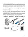
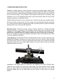
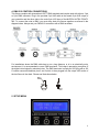
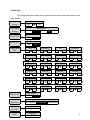
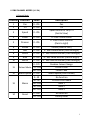
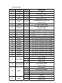
1
1. INTRODUCTION AND UNPACKING
Thank you for purchasing the MICROH LED HALO ZOOM19 MKII moving head fixture. For your
own safety and knowledge, please read this manual before installing or operating the device.
This manual covers the important information on installation and applications. Please install and
operate the fixture according to instructions. Meanwhile, please keep this manual for future
reference.
The MICROH LED HALO ZOOM19 MKII model is a moving head light with the latest
advancements in smart, efficient product design. Combined with the advanced technology of
today's stage lighting products, advanced control technology and is very user-friendly; this unit
fully complies with CE standards.
The MICROH LED HALO ZOOM19 MKII has a beam angle of 8° to 50°, obtained via motorized
zoom control. The LED HALO ZOOM19 MKII has smooth LED dimming, LED rainbow effect
using RGBW, 10 built-in Marcos, 14CH and 24CH DMX modes, Neutrik Powercon IN/OUT also
has 3 and 5 pin DMX IN/OUT. This fixture is perfect for use in television, banquet and convention
centres, nightclubs, large-scale performances and other professional venues. Please carefully
unpack the fixture when you receive it and check to see if it was damaged during the
transportation. Please check whether the following items are included inside the box:
Fixture – One
User Manual – One
Power Cord – One
Omega Bracket – One
Power Out Connector – One
Safety Cable – One
DMX Cable - One
2
2. SAFTEY INSTRUCTIONS
This device has been delivered in safe working condition. In order to maintain this condition and
to ensure safe operation, it is absolutely necessary for the user to follow the safety instructions
and warning notes written in this user manual.
If the device has been exposed to temperature changes, do not switch it on immediately. The
arising condensation could damage the device. Leave the device switched off until it has reached
room temperature, and is dry.
This device falls under protection-class I, therefore it is essential that the device be grounded.
The electrical connection must be carried out by a qualified technician.
The device should only be used with rated voltage and frequency. Make sure that the available
voltage is not higher than 120V as stated at the end of this manual.
Make sure the power cord is never crimped or damaged in any way, as this could cause shock
and damage. If your power cord is damaged in any way, please purchase a new cable from your
local MICROH dealer. Always disconnect power, when the device is not in use or before cleaning
it. Never pull out the plug by tugging the power cord.
During initial start-up, some smoke or smell may arise. This is a normal process, and does not
necessarily mean that the device is defective. It should decrease gradually. Please do not project
the beam onto combustible substances.
Fixtures cannot be installed on or near combustible substances. Keep more than 3m distance
from wall for proper ventilation and air flow. If your fixture is or has become damaged in any way,
it shall be exclusively replaced or repaired by the manufacturer to avoid any hazard.
3
3. MOUNTING AND INSTALLATION
Caution: For added protection, mount the fixtures in areas outside walking paths, seating areas,
or in areas were the fixture might be reached by unauthorized personnel. Before mounting the
fixture to any surface, make sure that the installation area can hold a minimum point load of 10
times the device’s weight. Fixture installation must always be secured with a secondary safety
attachment, such as an appropriate safety cable. Never stand directly below the device when
mounting, removing, or servicing the fixture.
Whether installing inverted on a truss, ceiling or set on a flat level surface (see illustration below).
Be sure this fixture is kept at least 3m (3.3 ft.) away from any flammable materials (decoration
etc.). Always use and install the supplied safety cable as a safety measure to prevent accidental
damage and/or injury in the event the clamp fails.
Mounting Points: Overhead mounting requires extensive experience, including calculating
working load limits. A knowledge of the installation material being used and periodic safety
inspection of all installation material and the fixture are all imperative and should only be
performed by a qualified technician. Improper installation can result in bodily injury and damage.
Be sure to complete all rigging and installation procedures before connecting the main power
cord to the appropriate wall outlet.
Clamp Mounting: The MICROH LED HALO ZOOM19 MKII provides a unique mounting bracket
assembly that integrates 2 brackets to be used to mount on a truss or the floor. When mounting
this fixture to truss, be sure to secure an appropriately rated clamp to the included bracket fitted
through the center hole. As an added safety measure, be sure to attach at least one properly
rated safety cable to the fixture.
Regardless of the rigging option you choose for your MICROH LED HALO ZOOM19 MKII,
always be sure to secure your fixture with a safety cable. The fixture provides a built-in rigging
point for a safety cable on the hanging bracket as illustrated above. Be sure to only use the
designated rigging point for the safety cable and never secure a safety cable to a carrying
handle.
4
4. DMX-512 CONTROL CONNECTIONS
This fixture complies with international USITT DMX standards and can be used with either a 3 pin
or 5 pin DMX connector. Plug in the provided 3 pin XLR cable to the female 3-pin XLR output of
your controller and the other side to the male 3-pin XLR input of the MICROH ULTRA TRINITY
280. To connect the units to DMX, you must daisy chain the fixtures together as referred in the
diagram below. Always end your DMX-512 connection with a DMX terminator.
For installations where the DMX cable has to run a long distance, or is in an electrically noisy
environment, it is recommended to use a DMX terminator. This helps in preventing corruption of
the digital control signal by electrical noise. The DMX terminator is simply an XLR plug with a 120
Ω resistor connected between pins 2 and 3,which is then plugged into the output XLR socket of
the last fixture in the chain. Please see illustrations below.
120Ω
2
3
1
PIN 3
PIN 2
5. SETUP MENU
5
*Please Note:
The “Design Mode Set” allows you to re-allocate the position of the said control on your
DMX console.
DMX Address
Setting
Work Mode
Setting
DMX Address:
001
512
DMX512
Work Mode:
Slave
Sound Fast
Invert PAN
PAN Reversal:
YES
NO
Invert TILT
TILT Reversal:
YES
NO
Design Mode
Set*
DISPLAY SET
CHANNEL
MODE SET
Pan
Slow
024
PANMICO
001
024
024
TILTMICO
001
024
SPEED
001
024
FOCUS
001
024
024
STROBE
001
024
001
DIM_R0
001
024
DIM_G0
001
024
DIM_B0
001
024
DIM_W0
001
024
DIM_R1
001
024
DIM_G1
001
024
DIM_B1
001
024
DIM_W1
001
024
DIM_R2
001
024
DIM_G2
001
024
DIM_B2
001
024
DIM_W2
001
024
LIGHT EFFECT
001
024
LIGHT SPEED
001
024
MACRO_CH
001
024
RESET_CH
001
024
001
TILT
001
DIM
BACKLIGHT:
YES
NO
CHANNEL MODE:
14 CHANNEL 24 CHANNEL DESIGN MODE
RESTORE
FACTORY
LOAD DEFAULT
YES
RESET
RESET ALL
YES
6
6. DMX CHANNEL MODES (14 / 24)
14 Channel Mode:
Channel
Function
Value
Description
1
2
Pan
Tilt
0 - 255
0 - 255
3
Speed
0 - 255
4
Zoom
0 - 255
5
Dimmer
0 - 255
6
7
8
9
10
Strobe
Red
Green
Blue
White
Pan
Tilt
Speed control of Pan/Tilt
(Fast to Slow)
0 - 100% Linear Zoom
0 - 100% Linear Dimmer
(Dark to Light)
Strobe (Slow to Fast)
0 - 100% Red dimmer (Dark to Bright)
0 - 100% Green dimmer (Dark to Bright)
0 - 100% Blue dimmer (Dark to Bright)
0 - 100% White dimmer (Dark to Bright)
Random Colour Change
Colour Chase
Colour Fade
Macro Speed (Fast to Slow)
No Function
CH11 & CH12 Enable
Auto 1
Auto 2
Auto 3
No Function
Factory Reset
11
12
13
14
0 - 255
0 - 255
0 - 255
0 - 255
0 - 255
0 - 174
Colour Macro 175 - 199
200 - 255
Macro Speed 0 - 255
0 - 49
50 - 99
Macro
100 - 149
150 - 199
200 - 255
0 - 250
Reset
251 - 255
7
24 Channel Mode:
Channel
Function
Value
Description
1
2
3
4
Pan
Fine Pan
Tilt
Fine Tilt
0 - 255
0 - 255
0 - 255
0 - 255
5
Speed
0 - 255
6
Zoom
0 - 255
7
Dimmer
0 - 255
8
9
10
11
12
13
14
15
16
17
18
19
20
Strobe
Red 1
Green 1
Blue 1
White 1
Red 2
Green 2
Blue 2
White 2
Red 3
Green 3
Blue 3
White 3
Pan
Fine control of Pan
Tilt
Fine control of Tilt
Speed control of Pan/Tilt
(Fast to Slow)
0 - 100% Linear Zoom
0 - 100% Linear Dimmer
(Dark to Light)
Strobe (Slow to Fast)
0 - 100% Red 1 dimmer (Dark to Bright)
0 - 100% Green 1 dimmer (Dark to Bright)
0 - 100% Blue 1 dimmer (Dark to Bright)
0 - 100% White 1 dimmer (Dark to Bright)
0 - 100% Red 2 dimmer (Dark to Bright)
0 - 100% Green 2 dimmer (Dark to Bright)
0 - 100% Blue 2 dimmer (Dark to Bright)
0 - 100% White 2 dimmer (Dark to Bright)
0 - 100% Red 3 dimmer (Dark to Bright)
0 - 100% Green 3 dimmer (Dark to Bright)
0 - 100% Blue 3 dimmer (Dark to Bright)
0 - 100% White 3 dimmer (Dark to Bright)
Clour Change
Colour Chase
Colour Fade
CH21 Macro Speed
(Fast to Slow)
No Function
CH21 & CH22 Enable
Auto 1
Auto 2
Auto 3
No Function
Factory Reset
21
22
0 - 255
0 - 255
0 - 255
0 - 255
0 - 255
0 - 255
0 - 255
0 - 255
0 - 255
0 - 255
0 - 255
0 - 255
0 - 255
0 - 174
Colour Macro 175 - 199
200 - 255
Macro Speed 0 - 255
23
Macro
24
Reset
0 - 49
50 - 99
100 - 149
150 - 199
200 - 255
0 - 250
251 - 255
8
7. TECHNICAL SPECIFICATIONS
Power: 110~240V 295W
Frequency: 50/60Hz
LED’s: 19 x 15W OSRAM LE RTDUW S2W 4-in-1 LED’s
Fuse: 6A250V
Fixture Dimension: 185 x 310 x 400mm (7.28”x12.2”x15.75”)
Packing Dimensions: 290 x 356 x 430mm (11.4”x14”x17”)
Net Weight: 7.8Kg (17.2Lbs)
Gross Weight: 9.3Kg (20.5Lbs)
8. MAINTENANCE AND CLEANING
The following points have to be considered during the inspection:
1) All screws for installing the device or parts of the device must be tightly connected, and must
not be corroded.
2) There must not be any deformations on the housing, colour lenses, fixations or installation
spots (ceiling, suspension, trussing).
3) Mechanically moved parts must not show any traces of wearing and must not rotate with
unbalances.
4)The electric power supply cables must not show any damage, material fatigue or sediments.
Further instructions depending on the installation spot and usage must be handled by a skilled
installer or technician. Any safety issues must be resolved.
In order to keep the fixture in good condition and extend the life, we suggest regular cleaning to
the fixture.
1) Clean the inside and outside lens each week to avoid the light output from darkening due to
accumulation of dust, dirt, etc.
2) Clean the fan each week.
3) A detailed electrical check by approved technician every three months is advised. Ensure the
circuit contacts are in good condition.
9
We recommend a frequent cleaning of the device. Please use a moist, lint- free cloth. Never use
alcohol or solvents.
There are no serviceable parts inside the device. Please refer to the instructions under
“Installation instructions”.
Should you need any spare parts, please order genuine MICROH parts from your local dealer.
IF YOU SHOULD EXPERIENCE ANY PROBLEMS OR ISSUES PLEASE CONTACT MICROH
PROFESSIONAL PRODUCTS BY EMAIL AT [email protected]
In the event that your unit is defective in any way, please contact your local dealer to
obtain an RA number for service repair.
DISCLAIMER – MICROH believes that the information contained within this user manual is
accurate. However, MICROH is not responsible for any error or addendums to this manual.
If you have any comments or general suggestions on how this manual can be improved
please contact [email protected]. Thank you.
10