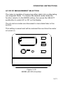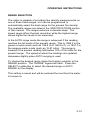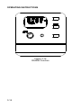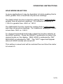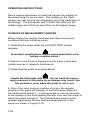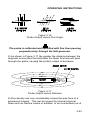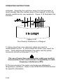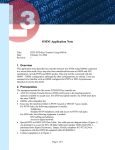
1
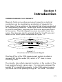
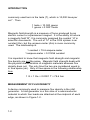
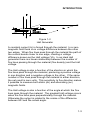
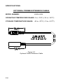
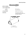
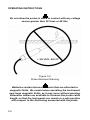
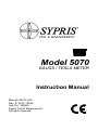
Model 5070
GAUSS / TESLA METER
Instruction Manual
Manual UN-01-230
Rev. E, ECO 13096
Item No. 359925
Sypris Test & Measurement
All rights reserved.
This symbol appears on the instrument and probe. It
refers the operator to additional information
contained in this instruction manual, also identified
by the same symbol.
NOTICE:
See Pages 3-1 and 3-2
for SAFETY
instructions prior to first use !
Table of Contents
SECTION-1 INTRODUCTION
Understanding Flux Density..............................................
Measurement of Flux Density............................................
Product Description...........................................................
Applications.......................................................................
1-1
1-2
1-5
1-6
SECTION-2 SPECIFICATIONS
Instrument.........................................................................
Standard Transverse Probe..............................................
Standard Axial Probe........................................................
Optional Probe Extension Cable.......................................
Zero Flux Chamber............................................................
2-1
2-3
2-4
2-5
2-6
SECTION-3 OPERATING INSTRUCTIONS
Operator Safety.................................................................
Operating Features...........................................................
Instrument Preparation......................................................
Power-Up..........................................................................
Power-Up Settings............................................................
Low Battery Condition.......................................................
Overrange Condition.........................................................
AC or DC Measurement Selection.....................................
UNITS of Measurement Selection.....................................
RANGE Selection..............................................................
HOLD Mode Selection.......................................................
MIN / MAX Hold Usage......................................................
ZERO Function..................................................................
Automatic ZERO Function.................................................
Manual ZERO Function.....................................................
Sources of Measurement Errors........................................
More details on AC Mode Operation.................................
More details on DC Mode Operation.................................
i
3-1
3-3
3-5
3-7
3-8
3-9
3-10
3-11
3-12
3-13
3-15
3-16
3-17
3-18
3-20
3-22
3-25
3-26
WARRANTY....................................................................
4-1
List of Illustrations
Figure 1-1
Figure 1-2
Figure 1-3
Figure 2-1
Figure 2-2
Figure 2-3
Figure 2-4
Figure 3-1
Figure 3-2
Figure 3-3
Figure 3-4
Figure 3-5
Figure 3-6
Figure 3-7
Figure 3-8
Figure 3-9
Figure 3-10
Figure 3-11
Figure 3-12
Figure 3-13
Figure 3-14
Figure 3-15
Figure 3-16
Figure 3-17
Figure 3-18
Figure 3-19
Flux Lines of a Permanent Magnet............
Hall Generator............................................
Hall Probe Configurations..........................
Standard Transverse Probe.......................
Standard Axial Probe.................................
Optional Probe Extension Cable................
Zero Flux Chamber....................................
Auxiliary Power Connector Warnings.........
Probe Electrical Warning...........................
Operating Features....................................
Battery Installation.....................................
Probe Connection......................................
Power-Up Display......................................
Missing Probe Indication............................
Low Battery Indication................................
Overrange Indication ................................
MODE (AC-DC) Function...........................
UNITS Function..........................................
RANGE Function.......................................
HOLD Function..........................................
Automatic ZERO Function.........................
Manual ZERO Function..............................
Probe Output versus Flux Angle................
Probe Output versus Distance...................
Flux Density Variations in a Magnet...........
Low AC Signal Indication...........................
ii
1-1
1-3
1-4
2-3
2-4
2-5
2-6
3-1
3-2
3-3
3-5
3-6
3-7
3-8
3-10
3-10
3-11
3-12
3-14
3-16
3-19
3-21
3-23
3-23
3-24
3-25
Section 1
Introduction
UNDERSTANDING FLUX DENSITY
Magnetic fields surrounding permanent magnets or electrical
conductors can be visualized as a collection of magnetic flux
lines; lines of force existing in the material that is being subjected
to a magnetizing influence. Unlike light, which travels away from
its source indefinitely, magnetic flux lines must eventually return
to the source. Thus all magnetic sources are said to have two
poles. Flux lines are said to emanate from the “north”pole and
return to the “south”pole, as depicted in Figure 1-1.
Figure 1-1
Flux Lines of a Permanent Magnet
One line of flux in the CGS measurement system is called a
8
maxwell (M), but the weber (W), which is 10 lines, is more
commonly used.
Flux density, also called magnetic induction, is the number of flux
lines passing through a given area. It is commonly assigned the
symbol “B”in scientific documents. In the CGS system a gauss
(G) is one line of flux passing through a 1 cm2 area. The more
1-1
INTRODUCTION
commonly used term is the tesla (T), which is 10,000 lines per
cm2 . Thus
1 tesla = 10,000 gauss
1 gauss = 0.0001 tesla
Magnetic field strength is a measure of force produced by an
electric current or a permanent magnet. It is the ability to induce
a magnetic field “B”. It is commonly assigned the symbol “H”in
scientific documents. The unit of “H”in the CGS system is an
oersted (Oe), but the ampere-meter (Am) is more commonly
used. The relationship is
1 oersted = 79.6 ampere-meter
1 ampere-meter = 0.01256 oersted
It is important to know that magnetic field strength and magnetic
flux density are not the same. Magnetic field strength deals with
the physical characteristics of magnetic materials whereas flux
density does not. The only time the two are considered equal is
in free space (air). Only in free space is the following relationship
true:
1 G = 1 Oe = 0.0001 T = 79.6 Am
MEASUREMENT OF FLUX DENSITY
A device commonly used to measure flux density is the Hall
generator. A Hall generator is a thin slice of a semiconductor
material to which four leads are attached at the midpoint of each
edge, as shown in Figure 1-2.
1-2
INTRODUCTION
Figure 1-2
Hall Generator
A constant current (Ic) is forced through the material. In a zero
magnetic field there is no voltage difference between the other
two edges. When flux lines pass through the material the path of
the current bends closer to one edge, creating a voltage
difference known as the Hall voltage (Vh). In an ideal Hall
generator there is a linear relationship between the number of
flux lines passing through the material (flux density) and the Hall
voltage.
The Hall voltage is also a function of the direction in which the
flux lines pass through the material, producing a positive voltage
in one direction and a negative voltage in the other. If the same
number of flux lines pass through the material in either direction,
the net result is zero volts. This sensitivity to flux direction makes
it possible to measure both static (dc) and alternating (ac)
magnetic fields.
The Hall voltage is also a function of the angle at which the flux
lines pass through the material. The greatest Hall voltage occurs
when the flux lines pass perpendicularly through the material.
Otherwise the output is related to the cosine of the difference
between 90° and the actual angle.
1-3
INTRODUCTION
The sensitive area of the Hall generator is generally defined as
the largest circular area within the actual slice of the material.
This active area can range in size from 0.2 mm (0.008”) to 19
mm (0.75”) in diameter. Often the Hall generator assembly is too
fragile to use by itself so it is often mounted in a protective tube
and terminated with a flexible cable and a connector. This
assembly, known as a Hall probe, is generally provided in two
configurations:
Figure 1-3
Hall Probe Configurations
In “transverse”probes the Hall generator is mounted in a thin, flat
stem whereas in “axial”probes the Hall generator is mounted in a
cylindrical stem. The axis of sensitivity is the primary difference,
as shown by “B”in Figure 1-3. Generally transverse probes are
used to make measurements between two magnetic poles such
as those in audio speakers, electric motors and imaging
machines. Axial probes are often used to measure the magnetic
field along the axis of a coil, solenoid or traveling wave tube.
Either probe can be used where there are few physical space
limitations, such as in geomagnetic or electromagnetic
interference surveys.
1-4
INTRODUCTION
Handle the Hall probe with care. Do not bend the stem or
apply pressure to the probe tip as damage may result. Use
the protective cover when the probe is not in use.
PRODUCT DESCRIPTION
The MODEL 5070 GAUSS / TESLAMETER is a portable
instrument that utilizes a Hall probe to measure magnetic flux
density in terms of gauss, tesla or ampere-meter. The
measurement range is from 0.01 mT (0.1 G or 0.01 kAm) to
1.999T (19.99 kG or 1591 kAm). The instrument is capable of
measuring static (dc) magnetic fields and alternating (ac) fields.
The MODEL 5070 consists of a palm-sized meter and various
detachable Hall probes. The meter operates on standard 9 volt
alkaline batteries or can be operated with an external ac-to-dc
power supply. A retractable bail allows the meter to stand upright
on a flat surface. A notch in the bail allows the meter to be wall
mounted when bench space is at a premium. The large display is
visible at considerable distances. The instrument is easily
configured using a single rotary selector and two pushbuttons.
Three measurement ranges can be selected or the meter can
automatically select the best range based on the present flux
density being measured. A “zero”function allows the user to
remove undesirable readings from nearby magnetic fields
(including earth’s) or false readings caused by initial electrical
offsets in the probe and meter. Included is a “zero flux chamber”
which allows the probe to be shielded from external magnetic
fields during this operation. The “zero”adjustment can be made
manually or automatically.
1-5
INTRODUCTION
Other features include two “hold”modes, allowing either the
arithmetic maximum or minimum values to be held indefinitely
until reset by the user.
The meter, probes and accessories are protected when not in
use by a sturdy carrying case.
APPLICATIONS
•
•
•
•
•
•
•
•
1-6
Sorting or performing incoming inspection on permanent
magnets, particularly multi-pole magnets.
Testing audio speaker magnet assemblies, electric motor
armatures and stators, transformer lamination stacks, cut
toroidal cores, coils and solenoids.
Determining the location of stray fields around medical
diagnostic equipment.
Determining sources of electromagnetic interference.
Locating flaws in welded joints.
Inspection of ferrous materials.
3-dimensional field mapping.
Inspection of magnetic recording heads.
Section 2
Specifications
INSTRUMENT
RANGE
GAUSS
200 G
2 kG
20 kG
TESLA
20 mT
200 mT
2 T
RESOLUTION
Am
16 kAm
159 kAm
1591 kAm
GAUSS
0.1 G
1G
10 G
TESLA
0.01 mT
0.1 mT
1 mT
Am
0.01 kAm
0.1 kAm
1 kAm
ACCURACY (including probe):
dc mode:
± 2 % of reading, ± 3 counts
ac mode:
20 - 10,000 Hz:
± 3.5 % of reading, ± 5 counts
ACCURACY CHANGE WITH
TEMPERATURE
(not including probe):
± 0.02 % / ºC typical
WARMUP TIME TO RATED
ACCURACY:
15 minutes
MIN / MAX HOLD ACQUISITION TIME:
dc mode:
ac mode:
180 ms typical
300 ms typical
BATTERY TYPE:
9 Vdc alkaline (NEDA 1640A)
BATTERY LIFE:
8 hours typical (two batteries)
2-1
SPECIFICATIONS
AUXILIARY POWER:
9 Vdc, 300 mA
AUXILIARY POWER CONNECTOR:
Standard 2.5 mm I.D. / 5.5 mm
O.D. connector. Center post is
positive (+) polarity.
OPERATING TEMPERATURE:
0 to +50ºC (+32 to +122ºF)
STORAGE TEMPERATURE:
-25 to +70ºC (-13 to +158ºF)
METER DIMENSIONS:
Length:
Width:
Height:
13.2 cm (5.2 in)
13.5 cm (5.3 in)
3.8 cm (1.5 in)
WEIGHT:
Meter w/batteries:
Shipping:
400 g (14 oz.)
1.59 kg (3 lb., 8 oz.)
REGULATORY INFORMATION:
Compliance was demonstrated to the following specifications as
listed in the official Journal of the European Communities:
EN 50082-1:1992
IEC 801-2:1991
Second Edition
IEC 1000-4-2:1995
Electrostatic Discharge
Immunity
ENV 50140:1993
IEC 1000-4-3:1995
Radiated Electromagnetic
Field Immunity
EN 50081-1:1992
EN 55011:1991
2-2
Generic Immunity
Generic Emissions
Radiated and Conducted
Emissions
SPECIFICATIONS
STANDARD TRANSVERSE PROBE
MODEL NUMBER:
STH57-0404
FLUX DENSITY RANGE:
0 to ± 2 T (0 to ± 20 kG)
FREQUENCY BANDWIDTH:
0 - 10 kHz
OFFSET CHANGE WITH
TEMPERATURE:
± 30 µT (300 mG) / ºC typical
ACCURACY CHANGE WITH
TEMPERATURE:
- 0.05% / ºC typical
OPERATING TEMPERATURE RANGE: 0 to +75ºC (+32 to +167ºF)
STORAGE TEMPERATURE RANGE: -25 to +75ºC (-13 to +167ºF)
Figure 2-1
Standard Transverse Probe
2-3
SPECIFICATIONS
STANDARD AXIAL PROBE
MODEL NUMBER:
SAH57-1904
FLUX DENSITY RANGE:
0 to ± 2 T (0 to ± 20 kG)
FREQUENCY BANDWIDTH:
0 - 10 kHz
OFFSET CHANGE WITH
TEMPERATURE:
± 30 µT (300 mG) / ºC typical
ACCURACY CHANGE WITH
TEMPERATURE:
- 0.05% / ºC typical
OPERATING TEMPERATURE RANGE: 0 to +75ºC (+32 to +167ºF)
STORAGE TEMPERATURE RANGE: -25 to +75ºC (-13 to +167ºF)
Figure 2-2
Standard Axial Probe
2-4
SPECIFICATIONS
2-5
SPECIFICATIONS
OPTIONAL PROBE EXTENSION CABLE
MODEL NUMBER:
X5000-0006
OPERATING TEMPERATURE RANGE: 0 to +75ºC (+32 to +167ºF)
STORAGE TEMPERATURE RANGE: -25 to +75ºC (-13 to +167ºF)
Figure 2-3
Optional Probe Extension Cable
2-6
SPECIFICATIONS
ZERO FLUX CHAMBER
MODEL NUMBER:
YA-111
CAVITY DIMENSIONS:
Length:
Diameter:
50.8 mm (2”)
8.7 mm (0.343”)
ATTENUATION:
80 dB to 30 mT (300 G)
PURPOSE:
To shield the probe from
external magnetic fields during
the ZERO operation.
Figure 2-4
Zero Flux Chamber
2-7
Section 3
Operating Instructions
OPERATOR SAFETY
Do not connect the auxiliary power connector to an ac power
source. Do not exceed 15 Vdc regulated or 9 Vdc
unregulated. Do not reverse polarity. Use only a regulated
ac-to-dc power supply certified for country of use.
Figure 3-1
Auxiliary Power Connector Warnings
3-1
OPERATING INSTRUCTIONS
Do not allow the probe to come in contact with any voltage
source greater than 30 Vrms or 60 Vdc.
Figure 3-2
Probe Electrical Warning
Batteries contain ferrous materials that are attracted to
magnetic fields. Be careful when operating the instrument
near large magnetic fields, as it may move without warning.
Extension cables are available to increase the probe cable
length, so that the instrument can remain in a safe position
with respect to the field being measured with the probe.
3-2
OPERATING INSTRUCTIONS
OPERATING FEATURES
Figure 3-3
Operating Features
1
Display. Liquid crystal display (LCD).
2
Manual ZERO Control. In the ZERO mode of operation
the user can manually adjust the zero point using this
control.
3
Function Selector. This control allows the operator to
change the meter’s range, units of measure, ac or dc
measurement and hold modes. It also engages the
ZERO and MEASURE modes of operation.
4
Battery Compartment Cover. This cover slides open to
allow one or two 9 volt batteries to be installed.
5
Power Switch. Push-on / push-off type switch to apply
power to the meter.
3-3
OPERATING INSTRUCTIONS
6
SELECT Switch. Momentary pushbutton used in
conjunction with the Function Selector 3 to configure
the meter’s range, units of measure, ac or dc
measurement and hold modes.
7
AUTO/HOLD RESET Switch. Momentary pushbutton
used to reset the held reading when one of the HOLD
modes is being used, or to start an automatic ZERO
operation when in the ZERO mode.
8
Auxiliary Power Connector. This is an industry standard
2.5 mm I.D. / 5.5 mm O.D. dc power connector. The
meter will accept a regulated dc voltage in the range of 6 15 Vdc at 300 mA minimum current or unregulated 9 Vdc.
The center pin is positive (+). The internal batteries are
disconnected when using this connector.
Do not connect the auxiliary power connector to an ac power
source. Do not exceed 15 Vdc regulated or 9 Vdc
unregulated. Do not reverse polarity. Use only a regulated
ac-to-dc power supply certified for country of use.
9
Probe Connector. The Hall probe or probe extension
cable plugs into this connector and locks in place. To
disconnect, pull on the body of the plug, not the cable !
10
Meter Stand. Retractable stand that allows the meter to
stand upright when placed on a flat surface. A notch in
the stand allows the meter to be mounted to a vertical
surface.
3-4
OPERATING INSTRUCTIONS
INSTRUMENT PREPARATION
1) With the power switch turned off (POWER pushbutton in the
full up position) apply pressure to the battery compartment cover
at the two points shown in Figure 3-4. Slide the cover open and
remove.
2) Install one or two 9 volt alkaline batteries (two batteries will
provide longer operating life). The battery compartment is
designed so that the battery polarity cannot be reversed.
Reinstall the battery compartment cover.
Figure 3-4
Battery Installation
3-5
OPERATING INSTRUCTIONS
3) If using an ac-to-dc power supply review Figure 3-1 for safety
notes and the SPECIFICATIONS section for voltage and current
ratings. When using a power supply the batteries are
automatically disconnected.
4) Install the probe or probe extension cable by matching the key
way in the connector to that in the mating socket in the meter.
The connector will lock in place. To disconnect, pull on the body
of the plug, not the cable!
Figure 3-5
Probe Connection
3-6
OPERATING INSTRUCTIONS
POWER-UP
Depress the POWER switch. There will be a momentary audible
beep and all display segments will appear on the display.
Figure 3-6
Power-Up Display
The instrument will conduct a self test before measurements
begin. If a problem is detected the phrase “Err”will appear on the
display followed by a 3-digit code. The circuitry that failed will be
retested and the error code will appear after each failure. This
process will continue indefinitely or until the circuitry passes the
test. A condition in which a circuit fails and then passes should
not be ignored because it indicates an intermittent problem that
should be corrected.
If the self test is successful the meter will perform a self
calibration. During this phase the meter will display the software
revision number, such as “r 1.0”. Calibration will halt if there is no
Hall probe connected. Until the probe is connected the phrase
“Err”will appear accompanied by a flashing “PROBE”annunciator
as shown in Figure 3-7.
3-7
OPERATING INSTRUCTIONS
Figure 3-7
Missing Probe Indication
After power-up the position of the FUNCTION selector switch will
determine what happens next. For instance if the selector is in
the RANGE position the meter will wait for the user to change the
present range. If in the MEASURE position flux density
measurements will begin.
Allow adequate time for the meter and probe to reach a stable
temperature. See the SPECIFICATIONS section for specific
information.
POWER-UP SETTINGS
The meter permanently saves certain aspects of the instrument’s
setup and restores them the next time the meter is turned on.
The conditions that are saved are:
RANGE setting (including AUTO range)
MODE (ac or dc)
UNITS of measure (gauss, tesla or ampere-meter)
HOLD mode (min or max)
3-8
OPERATING INSTRUCTIONS
Other aspects are not saved and default to these conditions:
ZERO mode (inactive)
NOTE: The present setup of the instrument is saved only when
the FUNCTION selector is returned to the MEASURE position.
For example assume the meter is in the MEASURE mode on the
20 mT range. The FUNCTION selector is now turned to the
RANGE position and the 200 mT range is selected. The meter is
turned off and on again. The meter will be restored to the 20 mT
range because the FUNCTION selector was never returned to the
MEASURE mode prior to turning it off.
LOW BATTERY CONDITION
The meter is designed to use one or two standard 9V alkaline
batteries (two batteries will provide longer operating life). When
the battery voltage becomes too low the battery symbol on the
display will flash, as shown in Figure 3-8. Replace the batteries
or use an external ac-to-dc power supply.
Instrument specifications are not guaranteed when a low
battery condition exists !
3-9
OPERATING INSTRUCTIONS
Figure 3-8
Low Battery Indication
OVERRANGE CONDITION
If the magnitude of the magnetic flux density exceeds the limit of
the selected range the meter will display a flashing value of
“1999”(gauss or tesla mode) or “1591”(ampere-meter mode).
The next highest range should be selected. If already on the
highest range then the flux density is too great to be measured
with this instrument.
Figure 3-9
Overrange Indication
3-10
OPERATING INSTRUCTIONS
AC OR DC MEASUREMENT SELECTION
The meter is capable of measuring either static (dc) or alternating
(ac) magnetic fields. To choose the desired mode rotate the
function selector to the MODE setting, then press the SELECT
pushbutton to select AC or DC on the display.
The dc and ac modes are discussed in more detail later in this
section.
This setting is saved and will be restored the next time the meter
is turned on.
Figure 3-10
MODE (AC-DC) Function
3-11
OPERATING INSTRUCTIONS
UNITS OF MEASUREMENT SELECTION
The meter is capable of providing flux density measurements in
terms of gauss (G), tesla (T) or ampere-meters (Am). To choose
the desired units, rotate the function selector to the UNITS
position. Press the SELECT pushbutton to select G, T or Am on
the display.
This setting is saved and will be restored the next time the meter
is turned on.
Figure 3-11
UNITS Function
3-12
OPERATING INSTRUCTIONS
RANGE SELECTION
The meter is capable of providing flux density measurements on
one of three fixed ranges, or it can be programmed to
automatically select the best range for the present flux density.
The available ranges are listed in the SPECIFICATIONS section
of this manual. The ranges advance in decade steps. The
lowest range offers the best resolution while the highest range
allows higher flux levels to be measured.
In the AUTO range mode the range is advanced if the reading
reaches the full scale of the present range. This is 1999 if in the
gauss or tesla mode (such as 199.9 G or 199.9 mT), or 1591 if in
the ampere-meter mode (such as 15.91 kAm). The range is
lowered if the present reading falls below 10% of full scale for the
present range. The speed at which the readings are updated
decreases slightly when AUTO ranging is used.
To choose the desired range rotate the function selector to the
RANGE position. The “RANGE”legend will flash. Press the
SELECT pushbutton to select the desired range or AUTO
RANGE on the display.
This setting is saved and will be restored the next time the meter
is turned on.
3-13
OPERATING INSTRUCTIONS
Figure 3-12
RANGE Function
3-14
OPERATING INSTRUCTIONS
HOLD MODE SELECTION
In some applications it may be desirable to hold a reading that is
either greater than or less than all previous readings.
The MAX HOLD function holds the reading that is arithmetically
greater than all previous readings. For instance a reading of
+125.0 is greater than +99.0 or -150.0.
The MIN HOLD function holds the reading that is arithmetically
less than all previous readings. For instance a reading of -125.0
is less than -99.0 or +150.0.
To choose the desired hold mode rotate the function selector to
the HOLD position. Press the SELECT pushbutton to select the
desired mode on the display. MAX HOLD is indicated by “MX”.
MIN HOLD is indicated by “MN”. The “OFF”legend will appear
when all HOLD modes are turned off.
This setting is saved and will be restored the next time the meter
is turned on.
3-15
OPERATING INSTRUCTIONS
Figure 3-13
HOLD Function
MIN / MAX HOLD USAGE
See the SPECIFICATIONS section for response time information.
The MAX HOLD function holds the reading that is arithmetically
greater than all previous readings. The MIN HOLD function holds
the reading that is arithmetically less than all previous readings.
These modes are useful in determining the maximum or minimum
value of magnetic events that occur over a period of time.
The MIN or MAX HOLD operation begins when the function
selector is returned to the MEASURE position. If the reading
3-16
OPERATING INSTRUCTIONS
exceeds the range limit the meter will hold a flashing value of
“1999”(gauss or tesla mode) or “1591”(ampere-meter mode).
The held value can be reset by pressing the HOLD RESET
pushbutton. The next value displayed after a reset will be the
present value of flux density. For instance if the held reading is
150.0 G and the present flux density is -100.0 G, the meter will
display -100.0 G after the reset.
ZERO FUNCTION
“Zeroing”the probe and meter is one of the most important steps
to obtaining accurate dc flux density measurements. The ideal
Hall generator produces zero output in the absence of a magnetic
field, but actual devices are subject to variations in materials,
construction and temperature. Therefore most Hall generators
produce some output even in a zero field. This will be interpreted
by the meter as a flux density signal.
Also, the circuits within the meter can produce a signal even
when there is no signal present at the input. This will be
interpreted as a flux density signal. Lastly magnetic sources
close to the actual field being measured, such as those from
electric motors, permanent magnets and the earth (roughly 0.5
gauss or 50 µT ), can induce errors in the final reading.
It is vital to remove these sources of error prior to making actual
measurements. The process of “zeroing”removes all of these
errors in one operation. The meter cancels the combined dc
error signal by introducing another signal of equal magnitude with
opposite polarity. After zeroing the only dc signal that remains is
that produced by the probe when exposed to magnetic flux.
3-17
OPERATING INSTRUCTIONS
NOTE: Zeroing the meter and probe affects only the static (dc)
component of the flux density signal.
There may be situations when the user prefers to shield the
probe from all external magnetic fields prior to zeroing. Provided
with the meter is a ZERO FLUX CHAMBER which is capable of
shielding against fields as high as 30 mT (300 G or 23.88 kAm).
The probe is simply inserted into the chamber before the zeroing
process begins.
Handle the Hall probe with care. Do not bend the stem or
apply pressure to the probe tip as damage may result.
In other situations the user may want the probe to be exposed to
a specific magnetic field during the zeroing process so that all
future readings do not include that reading (such as the earth’s
field). This is possible with the following restrictions:
1) The external field must not exceed 30 mT (300 G or
23.88 kAm).
2) The field must be stable during the zeroing process. It should
not contain alternating (ac) components.
AUTOMATIC ZERO FUNCTION
The meter provides two methods to zero the probe. The first is
completely automatic. Prepare the probe for zeroing, then rotate
the function selector to the ZERO position. The “ZERO”legend
will flash and actual dc flux density readings will appear on the
display. The meter will select the lowest range regardless of
which range was in use prior to using the ZERO function. Recall
that the maximum flux density level that can be zeroed is 30 mT
(300 G or 23.88 kAm). The meter will switch over to the dc mode
3-18
OPERATING INSTRUCTIONS
of operation during zeroing. Recall that the zeroing operation
affects dc errors only.
Figure 3-14
Automatic ZERO Function
Press the AUTO pushbutton and the process will begin. The
“AUTO”legend will also flash. Once automatic zeroing begins it
must be allowed to complete. During this time all controls are
disabled except for the POWER switch. The process normally
takes from 5 to 15 seconds.
3-19
OPERATING INSTRUCTIONS
The meter selects the lowest range and adjusts the nulling signal
until the net result reaches zero. If the existing field is too large
or unstable the meter will sound a double beep and the phrase
“OVER”will appear momentarily on the display. At this point the
automatic process is terminated and the flashing “AUTO”legend
will disappear. The “ZERO”legend will continue to flash to
remind the user that the ZERO mode is still active.
If the nulling process is successful, the next highest range is
selected. No further electronic adjustments are made, but at this
stage a reading is acquired which will be mathematically
subtracted from all future readings on this range. This process is
then repeated for the highest range. When finished, the meter
will sound an audible beep and the flashing “AUTO”legend will
disappear. The “ZERO”legend will continue to flash to remind
the user that the ZERO mode is still active. At this point the
automatic process can be repeated or a manual adjustment can
be performed (see “Manual Zeroing”).
The final zero values will remain in effect until the meter and
probe are zeroed again, if the probe is disconnected or if the
meter is turned off and back on again.
MANUAL ZERO FUNCTION
The second zeroing method is a manual adjustment. This
feature also allows the user to set the “zero”point to something
other than zero, if desired. Position the probe for zeroing, then
rotate the function selector to the ZERO position. The “ZERO”
legend will flash and actual dc flux density readings will appear
on the display. The meter will select the lowest range regardless
of which range was in use prior to selecting the ZERO function.
Recall that the maximum flux density level that can be zeroed is
30 mT (300 G or 23.88 kAm). The meter will switch over to the
3-20
OPERATING INSTRUCTIONS
dc mode of operation during zeroing. Recall that the zeroing
operation affects dc errors only.
Figure 3-15
Manual ZERO Function
By turning the MANUAL control in either direction the reading will
be altered. Turning the control clockwise adds to the reading,
turning it counterclockwise subtracts from the reading. Turning it
slowly results in a fine adjustment, turning it quickly results in a
coarse adjustment.
NOTE: Making a manual ZERO adjustment not only affects the
lowest range but also the higher ranges, though to a lesser
extent. For example, assume an automatic ZERO has already
been performed, after which all three ranges should read zero.
3-21
OPERATING INSTRUCTIONS
Now a manual adjustment is made that causes the reading on
the lowest range to be non-zero. The reading on the other
ranges may also be non-zero depending upon the magnitude of
the change. The adjustment has 10 times less effect on the
middle range and 100 times less effect on the highest range.
SOURCES OF MEASUREMENT ERRORS
When making flux density measurements there are several
conditions that can introduce errors:
1) Operating the meter while the LOW BATTERY symbol
appears.
Instrument specifications are not guaranteed when a low
battery condition exists !
2) Failure to zero the error signals from the meter, probe and
nearby sources of magnetic interference.
3) Subjecting the probe to physical abuse.
Handle the Hall probe with care. Do not bend the stem or
apply pressure to the probe tip as damage may result. Use
the protective cover when the probe is not in use.
4) One of the most common sources of error is the angular
position of the probe with respect to the field being measured.
As mentioned in Section-1, a Hall generator is not only sensitive
to the number of flux lines passing through it but also the angle at
which they pass through it. The Hall generator produces the
greatest signal when the flux lines are perpendicular to the
sensor as shown in Figure 3-16.
3-22
OPERATING INSTRUCTIONS
Figure 3-16
Probe Output versus Flux Angle
The probe is calibrated and specified with flux lines passing
perpendicularly through the Hall generator.
5) As shown in Figure 3-17 the greater the distance between the
magnetic source and the Hall probe the fewer flux lines will pass
through the probe, causing the probe’s output to decrease.
Figure 3-17
Probe Output versus Distance
6) Flux density can vary considerably across the pole face of a
permanent magnet. This can be caused by internal physical
flaws such as hairline cracks or bubbles, or an inconsistent mix of
3-23
OPERATING INSTRUCTIONS
materials. Generally the sensitive area of a Hall generator is
much smaller than the surface area of the magnet, so the flux
density variations are very apparent. Figure 3-18 illustrates this
situation.
Figure 3-18
Flux Density Variations in a Magnet
7) Using more than one extension cable can result in
measurement errors. In some cases the meter may report an
error. Total cable length between the meter and the probe
connector should not exceed 2.1 m (7 ft).
The use of more than one extension cable can result in
measurement errors and increase susceptibility to radio
frequency interference (RFI).
8) The accuracies of the meter and probe are effected by
temperature variations. Refer to the SPECIFICATIONS section
for specific information.
3-24
OPERATING INSTRUCTIONS
MORE DETAILS ON AC MODE OPERATION
It is possible for the flux density signal to contain both a dc
component and an ac component. In the ac mode the value
displayed is the true rms value of the waveform with its dc
component removed. However if the dc component is too high it
may force the peak value of the waveform to exceed the
electrical limits of the meter, causing the waveform to clip and
introducing errors in the final reading. This can also lead to an
overrange condition on the display and can lead to erratic
behavior if the AUTO range feature is being used.
As stated in the SPECIFICATIONS section the accuracy of the
true rms reading is only guaranteed for readings greater than 5%
of the full scale range. For example this would be 1mT on the
200 mT range. When the reading falls below 5% of full scale the
“AC”legend on the display will flash, as shown in Figure 3-19.
This is intended to remind the user that the reading may not be
accurate. Select a lower range if possible to regain accuracy.
Figure 3-19
Low AC Signal Indication
3-25
OPERATING INSTRUCTIONS
MORE DETAILS ON DC MODE OPERATION
It is possible for the flux density signal to contain both a dc
component and an ac component. In the dc mode this can lead
to instable readings. If the peak value of the ac component
reaches the electrical limits of the meter, even though the
average dc level is within the limits, an overrange condition may
appear on the display. This situation can also lead to erratic
behavior if the AUTO range feature is being used.
The presence of an ac signal can be verified by using the ac
mode to determine the magnitude of the ac component.
3-26
WARRANTY
This instrument is warranted to be free of defects in material and workmanship.
Sypris Test & Measurement’s obligation under this warranty is limited to
servicing or adjusting any instrument returned to the factory for that purpose,
and to replace any defective parts thereof. This warranty covers instruments
which, within one year after delivery to the original purchaser, shall be returned
with transportation charges prepaid by the original purchaser, and which upon
examination shall disclose to Sypris Test & Measurement’s satisfaction to be
defective. If it is determined that the defect has been caused by misuse or
abnormal conditions of operation, repairs will be billed at cost after submitting
an estimate to the purchaser.
Sypris Test & Measurement reserves the right to make changes in design at any
time without incurring any obligation to install same on units previously
purchased.
THE ABOVE WARRANTY IS EXPRESSLY IN LIEU OF ALL OTHER
WARRANTIES EXPRESSED OR IMPLIED AND ALL OTHER OBLIGATIONS
AND LIABILITIES ON THE PART OF SYPRIS TEST & MEASUREMENT, AND
NO
PERSON
INCLUDING
ANY
DISTRIBUTOR,
AGENT
OR
REPRESENTATIVE OF SYPRIS TEST & MEASUREMENT IS AUTHORIZED
TO ASSUME FOR SYPRIS TEST & MEASUREMENT ANY LIABILITY ON ITS
BEHALF OR ITS NAME, EXCEPT TO REFER THE PURCHASER TO THIS
WARRANTY.
THE ABOVE EXPRESS WARRANTY IS THE ONLY
WARRANTY MADE BY SYPRIS TEST & MEASUREMENT. SYPRIS TEST &
MEASUREMENT DOES NOT MAKE AND EXPRESSLY DISCLAIMS ANY
OTHER WARRANTIES, EITHER EXPRESSED OR IMPLIED, INCLUDING
WITHOUT
LIMITING
THE
FOREGOING,
WARRANTIES
OF
MERCHANTABILITY OR FITNESS FOR A PARTICULAR PURPOSE OR
ARISING BY STATUE OR OTHERWISE IN LAW OR FROM A COURSE OF
DEALING OR USAGE OR TRADE. THE EXPRESS WARRANTY STATED
ABOVE IS MADE IN LIEU OF ALL LIABILITIES FOR DAMAGES, INCLUDING
BUT NOT LIMITED TO CONSEQUENTIAL DAMAGES, LOST PROFITS OR
THE LIKE ARISING OUT OF OR IN CONNECTION WITH THE SALE,
DELIVERY, USE OR PERFORMANCE OF THE GOODS. IN NO EVENT WILL
SYPRIS TEST & MEASUREMENT BE LIABLE FOR SPECIAL, INDIRECT OR
CONSEQUENTIAL DAMAGES EVEN IF SYPRIS TEST & MEASUREMENT
HAS BEEN ADVISED OF THE POSSIBILITY OF SUCH DAMAGES.
This warranty gives you specific legal rights, and you may also have other rights
that vary from state to state.
4-1
6120 Hanging Moss Road
Orlando, Fl 32807
Phone: 407-678-6900
Fax: 407-677-5765
4-1