1
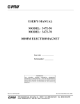
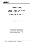
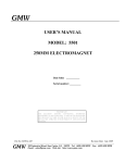
GMW
USER’S MANUAL
MODEL: 5403AC
63MM LAMINATED ELECTROMAGNET
Date Sold: _______________
Serial number: ___________
PROPRIETARY
THIS DOCUMENT CONTAINS CONFIDENTIAL INFORMATION
PROPRIETARY TO GMW ASSOCIATES. IT MUST NOT BE REPRODUCED
OR DISCLOSED TO OTHERS OR USED IN ANY WAY EXCECPT FOR THE
INSTALLATION, OPERATION OR MAINTENANCE OF GMW ASSOCIATES
PRODUCTS.
File No:
GMW
Revision Date: Oct 06, 2005
955 Industrial Road, San Carlos, CA 94070 Tel: (650) 802-8292
Email: [email protected] Web site: http://www.gmw.com
Fax: (650) 802-8298
TABLE OF CONTENTS
PHOTOGRAPHS
Model 5403AC 63mm Laminated Electromagnet
RC-351930 Bench Height Rack, Bipolar Power Supply, Front View
RC351930 Bench Height Rack, Bipolar Power Supply, Rear View
SPECIFICATIONS
Table 1 Model 5403AC Specifications
Table 2 Model 5403AC Electrical and Water Connections
Section 1
WARNINGS [ Refer to this section before operation of Electromagnet ]
Section 2
INSTALLATION
Unpacking Instructions
Mounting Position
Pole Selection and Installation
Electrical Circuit
Interlocks
Cooling
Section 3
OPERATION
General
Calibration
Field Control Operation
Section 4
MAINTENANCE
Section 5
STANDARD OPTIONS
Probe Holder
Section 6
CUSTOM OPTIONS
Section 7
EXCITATION CURVES
Section 8
TEST DATA
Drawing 18900740 Magnetic Plotting Axes
Section 9
DRAWINGS
Section 10
Drawing 11907-0008-0 5403AC Electromagnet General Assembly
Drawing 11907-0009-0 5403AC Electromagnet Yoke Assembly
Drawing 11907-0010-0 5403AC Electromagnet Pole Clamp Assembly
Drawing 11907-0018-0 5403AC Electromagnet Vertical Mount Assembly
Drawing 11907-0046-0 Rack Assembly, Copley 231P Amplifier
Drawing 13907-0000-0 5403AC & Copley 231P
Drawing 11907-0013-0 5403AC Pole, 38 x 38mm taper face.
Drawing 11907-0016-0 5403AC Pole, 32 x 32mm taper face.
Continued...
DRAWINGS
Drawing 17907-0017-0-16 5403AC Pole Spacer [for 32mm pole gap].
Drawing 17901610 5403AC Electromagnet Vertical Mount Bracket
Drawing 17901450 5403AC Electromagnet Angle Bracket
Drawing 18907-0002-0 5403AC Electromagnet Tool Kit
Drawing 18800770 5403AC Shipping Crate Assembly
Elmwood 3450 Thermostats
PHOTOGRAPHS
GMW Model 5403AC Laminated Electromagnet
63mm square poles tepered to 32mm square with a 32mm pole gap. The peak central field is
approximately ±1T at ±60A.
PHOTOGRAPHS
GMW RC-351930 Bench Height Rack – Front View
Shown equipped with 231P Power Amplifier and EMS 150-16 150V, 16A DC Power Supply. For
bipolar operation ±60A, ±160V, 1.8kW maximum. Refer to drawing 11907-0046-0 for layout
details.
PHOTOGRAPHS
GMW RC-351930 Bench Height Rack – Rear View
Shown equipped with 231P Power Amplifier and EMS 150-16 150V, 16A DC Power Supply. For
bipolar operation ±60A, ±160V, 1.8kW maximum. Refer to drawing 11907-0046-0 for layout
details and 13907-0000-0 for electrical details.
Section 1
SPECIFICATIONS
Table 1. Model 5403AC Specifications
Pole Size:
Pole Gap: (adjustable using pole spacers)
Square, 63 x 63mm (2.5 inch)
0 - 60mm (0 to 2.4 inch)
Standard Pole Face:
Square, 63 x 63mm (2.5 x 2.5 inch)
Square, 38 x 38mm (1.5 x 1.5 inch)
Square, 32 x 32mm (1.3 x 1.3 inch)
Square, 12 x 12mm (0.5 x 0.5 inch)
Coils (series connection)
coil resistance (20°C)
max resistance (hot)*
max continuous power (air)
max continuous power (water)
max intermittent power (water)
max peak voltage
Self Inductance
Water Cooling (18°C)
Overtemperature Interlock
Dimensions
Mass
0.45 Ohm
0.55 Ohm
20A/10V (0.2kW)
50A/25V (1.25kW)
100A/50V(5kW) for 3 min
500V
220mH
2 liters/m (0.5 US gpm) 0.5 bar (8 psid)
Elmwood 3450G thermostat part number
3450G 611-1 L50C 89/16 mounted on each coil
and wired in series. Contact rating 120Vac,0.5A.
Closed below 50°C.
Drawing 11907-0008-0
556mm W x 281mm D x 383mm H
21.9 inch W x 11.1 inch D x 15.1 inch H
125 kg (275 lb)
*CAUTION - The value of maximum coil resistance given should not be exceeded. At this
resistance the coils are at maximum safe temperature for continuous operation.
1-1
Section 1
SPECIFICATIONS
Table 2. Model 5403AC Electrical and Water Connections
DC Current (as seen from the front refer to Drawing 11907-0008-0)
Right hand terminal:
Negative
Left hand terminal:
Positive
Ground
An M6 screw (Item 31 on drawing 11907-0008-0) is inside the terminal cover to enable the magnet
frame to be grounded according to local safety regulations. It is normally appropriate to connect the
magnet frame to the power supply ground.
Interlocks (refer to Drawing 11907-0008-0).
The temperature interlock wiring connections are made directly onto the temperature thermostats (Item
17 on drawing 11907-0008-0).
Water (refer to Drawing 11907-0008-0).
Outlet
1/8 inch NPT
Inlet
1/8 inch NPT
(mating couplings for ¼ inch hose provided)
CAUTION - Ensure that the high current connections are tight. Loose connections may lead to
oxidation and overheating. The field stability may be degraded and the current terminations damaged.
1-2
Section 2
WARNINGS
REFER TO WARNINGS BELOW BEFORE OPERATING ELECTROMAGNET
1
Hazardous Voltages
THE 5403AC MAGNET HAS LETHAL VOLTAGES PRESENT DURING OPERATION.
VOLTAGES UP TO 500 VOLTS CAN BE PRESENT ACROSS THE MAGNET COILS. DO NOT
OPERATE THIS MAGNET WITHOUT THE TERMINAL COVER CORRECTLY INSTALLED.
2
Arcing
This magnet stores considerable energy in its field during operation. Do not disconnect any current
lead while under load or the magnetic field energy will be discharged across the interruption causing
hazardous arcing.
3
Fringing Magnetic Fields
In operation the magnet fringing field can be in excess of 0.5mT (5G) within about 1m of the
magnet. This can cause malfunctioning of heart pacemakers and other medical implants. We
recommend that the fringing field should be mapped and warning signs be placed outside the 0.5mT
(5G) contour. Entry to this region should be restricted to qualified personnel.
4
Ferromagnetic Objects
During operation the magnet can exert a strong magnetic force on ferromagnetic objects in the near
vicinity of its pole gap or coils. Loose objects can be accelerated to sufficient velocity to cause
personnel injury or damage to the coils or pole faces if struck. Keep ferromagnetic tools clear!
5
Draw/Clamp Bolts
Before operation always ensure that the clamp bolts (item 4 on drawing 11907-0010-0) are properly
tightened.
6
Interlocks
These should always be connected if the magnet is operated unattended, to avoid the possibility of
coil overheating caused by excessive power dissipation or inadequate cooling.
7
Watches, Credit Cards, and Magnetic Disks
Do not move magnetically sensitive items into the close vicinity of the magnet. Even some antimagnetic watches can be damaged when placed in close proximity to the pole gaps during operation.
Credit cards, and magnetic disks are affected by magnetic fields as low as 0.5mT (5G). Depending
on the previous operating field and the pole gap, the remanent field in the gap can be in excess of
50G (5mT) with the magnet power supply off or disconnected.
8
Coil Hot Resistance
Do not exceed the maximum coil hot resistance given in the specifications or coil overheating and
possible damage may occur.
2-1
Section 3
INSTALLATION
Caution: This electromagnet weighs 125kg (275lb). All movement, lifting and installation of the
5403AC Electromagnet must be under the supervision of an experienced person to prevent the
possibility of serious injury or damage to the Electromagnet and associated equipment.
Unpacking Instructions and Damage Inspection
To unpack the electromagnet please use the following procedure (Refer to Drawing 18900770).
1. First remove all of the "Hex Head Screws" located at the lower edge of all the side panels of the
"Crate Top Cover".
2. Gently rock the "Crate Top Cover" to work it loose from the shipping crate base.
3. Grip the side panels of the Crate Top Cover. Lift "Crate Top Cover" high enough to clear top of
electromagnet, walk cover sideways to a clear area and place on floor.
4. Inspect the magnet to ensure that no damage has occurred to the magnet in shipment. If damage is
evident report the damage in detail to the shipper for claim and simultaneously notify GMW in case
assessment of the damage must be made. If no damage is found proceed with magnet unpacking and
installation.
5. Remove the M12 hex head coach bolts that secure the magnet to the shipping crate base".
6. Install M12 lifting eyebolt and washer to top of magnet yoke, screw down firmly.
7. The magnet is now prepared for final installation. Follow the appropriate procedure for direct or
base mounting listed below.
Direct Mounting
1. With suitable lifting equipment e.g. 250kg (550 lb) minimum safe lifting rating, lift magnet 50mm
(2") clear of shipping crate base.
2. Slide shipping crate base clear.
3. Lower magnet to 50mm (2") above floor.
4. Move magnet to final location and bolt magnet down through the four mounting holes provided in
the magnet angle bracket (Item 4 on drawing 11907-0008-0).
3-1
Section 3
INSTALLATION
Pole Selection and Installation (Refer to drawing 11907-0008-0).
Using the field uniformity and induction curves determine the most desirable pole shape for the required
pole gap. In general, the pole face side dimension should be equal or greater than the pole gap.
Pole removal (refer to drawing 11907-0008-0 and 11907-0010-0).
1. Turn off the power supply.
2. Loosen the two pole clamping bolts two full turns (item 4 on drawing 11907-0010-0).
3. Remove the eight cap securing screws and lock washers (item 29 and 39 on drawing 11907-0008-0).
4. Pull off the pole retainers (item 6 on drawing 11907-0008-0).
5. Pull the pole and pole spacer out of the magnet yoke about 75mm (3 inches).
6. Grip the pole with pole hands and gently side the pole out of the magnet yoke.
Take care that the pole face is not damaged by contacting the magnet yoke.
7. Remove the pole retainer (item 6 on drawing 11907-0008-0).
Pole fitting (refer to drawing 11907-0008-0).
1. Ensure the poles and pole sleeves are clean and free from debris.
2. Reverse the above pole removal sequence above.
Electrical Circuit
NEVER CONNECT OR REMOVE CABLES FROM THE MAGNET WITH AC POWER ON THE
POWER SUPPLY. ). The terminal voltage may be lethal. The stored energy in the magnet can cause
arcing resulting in severe injury to personnel or equipment damage.
The magnet has two coils which are connected in series, (refer to drawing 11907-0008-0 and the power
supply cables should be connected directly to the current terminals marked + and -. Recommended
current cable for the 5403AC is stranded copper of 16mm² cross section (4 AWG).
Because the magnet operates at high currents, special care should be taken to insure that the current
terminations are secure and cannot work loose in operation. Local heating at the terminations can cause
rapid oxidation leading to a high contact resistance and high power dissipation at the terminals. If left
unattended this can cause enough local heating to damage the terminals and the coils.
3-2
Section 3
INSTALLATION
The 5403AC Interlocks
The Model 5403AC has two thermostats, Elmwood 3450G Part Number 3450G611-1 L50C 89/16.
They are located on the center coil cooling plate and wired in series. The thermostats are normally
closed, opening when the coil central cooling plate temperature exceeds 50°C +/3°C. When the Power
Supply is provided by GMW, either thermal switch opening will turn the Power Supply to zero current
until the switches reclose when the temperature drops below the nominal temperature. Note that the
Power Supply is not “latched” permanently off.
Cooling
The Model 5403AC can be operated to an average coil temperature of 70°C. Assuming an ambient
laboratory temperature of 20°C and a temperature coefficient of resistivity for copper of 0.0039/°C, the
hot resistance of the coil should not exceed 20% more than the ambient temperature "cold" resistance.
The coil thermostat will open when either center coil cooling plate temperature exceeds approximately
50°C . Clean, cool (16°C - 20°C) water at 2 l/min at 0.5 bar (8 psid) should be used to cool the 5403AC
magnet.
The cooling copper tubes are electrically isolated from the coils to avoid electrochemical corrosion. A 50
micron filter should be placed before the input to the magnet to trap particulate and avoid unreliable
operation of the water flow switch interlock (if fitted).
For continuous operation of the magnet it may be appropriate to use a recirculating chiller to reduce
water and drainage costs. The chiller capacity will depend on whether cooling is required for the magnet
alone or magnet and power supply. For the Model 5403AC Electromagnet alone, a suitable chiller is the
Bay Voltex Model: MC-050.
For recirculating cooling systems, use distilled or deionized water with a biocide to prevent bacterial
growth and corrosion. Do not use corrosion inhibitors in high quality electrical systems since the water
conductivity is increased which can result in increased leakage currents and electrochemical corrosion.
At currents of approximately 20A and below the Model 5403AC can be operated safely without water
cooling. However the coil temperature will vary with the power dissipation. This results in dimensional
changes of the magnet yoke and air cooling is not suitable when high field stability is required.
Freon, oil, ethylene glycol or other cooling mediums can be used. The flow required will be
approximately inversely proportional to their specific heats. An experimental determination of the flow
and pressure required will be necessary.
Avoid cooling the magnet below the dew point of the ambient air. Condensation may cause electrical
shorts and corrosion.
During operation the resistance can be checked using a voltmeter across each coil. The voltage will rise
to a constant value once thermal equilibrium has been reached. If it is desired to save water, the flow
can be reduced until the hot resistance is approached. NOTE: This adjustment must be made slowly
enough to allow for the thermal inertia of the coils.
3-3
Section 4
OPERATION
General
The 5403AC magnet yoke and poles consist of thin, electrically isolated magnetic steel sheets/(or
laminations) to reduce eddy current effects when the excitation current is changed. This results in fast
field settling. The 5403AC can be operated with sine wave excitation at frequencies to about 100Hz.
Due to the self inductance of about 220mH, even with a 500V applied voltage the peak current is limited
to about 3.6A at 100Hz.
The pole gap of the 5403AC is set by pole gap spacers between the yoke and a flange on the outer end of
the pole. Each pole gap spacer is of equal thickness and is half the desired pole gap. For a 20mm pole
gap the pole spacer thickness is 10mm, and it is Part No 17907-0017-0-10 . The suffix of the part no
denotes the pole spacer thickness.
Asymmetrical Pole Gap
For special applications and geometry requirements the pole gap can be asymmetrical in the yoke. In this
case the pole spacers will be of unequal thickness, Refer to drawing 17907-0017-0-XX for pole spacer
dimensional details.
Adjust the cooling water flow to about 2 liters/min (0.5 USgpm) for the 5403AC. For operation at less
than maximum power the water flow may be correspondingly reduced. Note that the inlet water
temperature will determine the actual flow rate required. The above specified flow rates were
determined with a water inlet temperature of approximately 18°C.
Current Excitation
The induction curves may be used to estimate the field in the air gap to within four or five percent. More
accurate field determination may be obtained by deriving experimentally a calibration curve for the
particular pole and pole gap combination being used. Magnetic hysteresis in the yoke and poles can
cause an error of 30 to 70G (3 to 7mT) with an arbitrary application of such a calibration curve. This
effect may be reduced to less than one percent by following a prescribed 'current setting schedule'
designed to make the magnet 'forget' its prior magnetic history. The schedule should be used both in
establishing the calibration curve and in its subsequent use. A possible schedule would be:
From zero current, increase to maximum current and reduce again to zero current. Increase again to
maximum current and reduce to the current to give the desired field setting. Approaching the desired
field from a higher setting will typically produce better field uniformity. This is because the field
changes at the pole edges will normally lag the field change at the center thereby helping to compensate
the radial decrease in field.
Greater precision in setting up the calibration curve will be achieved with the use of a magnetic field
teslameter and by making a numerical table. This table used with an interpolation routine will eliminate
the error associated with reading a graph.
Continued
4-1
Section 4
OPERATION
Three points need to be remembered:
1. A calibration curve or table is only as good as the precision employed in generating it.
2. The field is defined only at the point it is measured. It will generally be different at a different point
in the air gap. For example, the induction curves refer to the field on the pole axis and at the center of
the air gap (median plane).
3. The field is most directly a function of the current in the magnet coils. Voltage across the coils is not
a good measure of field since the electrical resistance of the coils depends on the temperature (about
0.4% per degree celsius).
4-2
Section 4
OPERATION
Field Control Operation
The necessity to use calibration curves can be avoided by using a field controller to sense the magnetic
field and provide a corresponding power supply control signal through the power supply programming
inputs. Contact GMW for suitable instrumentation.
4-3
Section 5
MAINTENANCE
Periodically check that the pole adjustment mechanism (when fitted) is clean, properly lubricated and
free of grit and dirt. Be very careful not to damage the relatively soft pole surface since this may degrade
the magnetic field uniformity in the gap.
Note that the surface treatments used provide good corrosion protection but in order to maintain the
inherent mechanical precision of the magnet, heavy build-up of plating material or paint is deliberately
avoided. As a result, high humidity or otherwise seriously corrosive atmospheres can cause corrosion.
Periodically apply an appropriate corrosion protection on plated components, particularly when the
magnet is stored for an extended period.
Check the cooling water circuit to ensure the water is clean and free of debris and bacterial growth.
Ensure the in-line water filter is clean.
5-1
Section 6
STANDARD OPTIONS
Drawing 11907-0015-0 5403AC Electromagnet/Probe Mount General Assembly
Section 7
CUSTOM OPTIONS
Section 8
EXCITATION CURVES
GMW ASSOCIATES
Electromagnet B vs.I Excitation
Model:
Serial No:
Pole Face:
Pole gap:
5403AC
1
32mmx32mm, square
32mm
Power Supply:
PS SN:
Position:
Copley 231P
2905901
X=Y=Z=0mm
I(A)
5.0684
9.9805
15.144
20.0439
25.2686
30.0488
35.1685
40.2417
45.1147
50.2466
55.2686
60.3931
Engr:
Date:
Page:
Bz(T) 1Hz, sine
0.1259
0.2495
0.3782
0.5
0.616
0.6956
0.7651
0.8218
0.8655
0.9048
0.9388
0.9708
I(A)
4.9898
9.9846
14.9934
20.0177
24.9843
29.9704
35.0431
40.0122
44.9789
50.0495
55.0206
59.9817
Y.Q.
10/4/2005
1 of 1
B(T) DC
0.125869
0.252405
0.378339
0.503581
0.616341
0.700792
0.769258
0.825283
0.871521
0.911013
0.945466
0.97675
1
0.9
0.8
0.7
Bz (T)
0.6
0.5
0.4
0.3
0.2
Bz(T) 1Hz, sine
0.1
B(T) DC
0
0
10
20
30
40
Current (A)
50
60
70
GMW ASSOCIATES
Electromagnet Hysteresis Plot
Model:
Serial No:
Pole Face:
Pole gap:
5403AC
1
32mmx32mm, square
32mm
Power Supply:
PS SN:
Position:
Current:
Copley 231P
2905901
X=Y=Z=0mm
DC
Engr:
Date:
Page:
Y.Q.
10/7/2005
1 of 1
1
0.8
0.6
0.4
Bz (T)
0.2
0
-0.2
-0.4
-0.6
Up Ramp
-0.8
Down Ramp
-1
-70
-50
-30
-10
10
Current (A)
30
50
70
0.05
0.04
0.03
0.02
Bz (T)
0.01
0
-0.01
-0.02
-0.03
Up Ramp
-0.04
Down Ramp
-0.05
-2
-1.5
-1
-0.5
0
Current (A)
0.5
1
1.5
2
GMW ASSOCIATES
Power Supply I vs. Vp
Power Supply:
Model:
PS SN:
Copley
231P
2905901
Engr:
Date:
Page:
Y.Q.
10/4/2005
1 of 1
80
60
40
Current (A)
20
0
-20
-40
-60
-80
-10
-8
-6
-4
-2
0
Vp(V)
2
4
6
8
10
Section 9
TEST DATA
GMW ASSOCIATES
Electromagnet: Typical Waveform
5403AC
1
32mmx32mm, square
32mm
Power Supply:
PS SN:
Position:
Current:
Frequency:
Waveform:
Copley 231P
2905901
X=Y=Z=0mm
I=+/-35A peak to Peak
1Hz
Sine
Bz (T)
Current(A)
Model:
Serial No:
Pole Face:
Pole gap:
Engr:
Date:
Page:
Y.Q.
10/4/2005
1 of 1
40
30
20
10
0
-10
-20
-30
-40
0
0.5
1
1.5
2
Time(second)
2.5
3
3.5
0
0.5
1
1.5
2
Time(second)
2.5
3
3.5
3
3.5
1
0.8
0.6
0.4
0.2
0
-0.2
-0.4
-0.6
-0.8
-1
Magnet Voltage (V)
60
40
20
0
-20
-40
-60
0
0.5
1
1.5Time(second)
2
2.5
GMW ASSOCIATES
Electromagnet: Typical Waveform
5403AC
1
32mmx32mm, square
32mm
Power Supply:
PS SN:
Position:
Current:
Frequency:
Waveform:
Copley 231P
2905901
X=Y=Z=0mm
I=+/-60A peak to Peak
1Hz
Sine
Current(A)
Model:
Serial No:
Pole Face:
Pole gap:
Engr:
Date:
Page:
Y.Q.
10/4/2005
1 of 1
80
60
40
20
0
-20
-40
-60
-80
0
0.5
1
1.5
Time (second)
2
2.5
3
0
0.5
1
1.5
Time (second)
2
2.5
3
0
0.5
1
1.5
Time (second)
2
2.5
3
1.5
Bz (T)
1
0.5
0
-0.5
-1
Magnet Voltage(V)
-1.5
80
60
40
20
0
-20
-40
-60
-80
GMW ASSOCIATES
Electromagnet: Typical Waveform
5403AC
1
32mmx32mm, square
32mm
Power Supply:
PS SN:
Position:
Current:
Frequency:
Waveform:
Copley 231P
2905901
X=Y=Z=0mm
I=+/-MAX (62A) Peak to Peak
1Hz
Sine
Current (A)
Model:
Serial No:
Pole Face:
Pole gap:
Engr:
Date:
Page:
Y.Q.
10/4/2005
1 of 1
80
60
40
20
0
-20
-40
-60
-80
0
0.5
1
1.5
2
Time(second)
2.5
3
3.5
4
0
0.5
1
1.5
2
Time(second)
2.5
3
3.5
4
2.5
3
3.5
4
1.5
Bz (T)
1
0.5
0
-0.5
-1
-1.5
Magnet Voltage(V)
100
80
60
40
20
0
-20
-40
-60
-80
-100
0
0.5
1
`
1.5
2
Time(second)
GMW ASSOCIATES
Electromagnet: Typical Waveform
5403AC
1
32mmx32mm, square
32mm
Power Supply:
PS SN:
Position:
Current:
Frequency:
Waveform:
Copley 231P
2905901
X=Y=Z=0mm
I=+/-60A peak to Peak
1Hz
Square
Current (A)
Model:
Serial No:
Pole Face:
Pole gap:
Engr:
Date:
Page:
Y.Q.
10/4/2005
1 of 1
80
60
40
20
0
-20
-40
-60
-80
0
0.5
1
1.5
2
Time (second)
2.5
3
3.5
0
0.5
1
1.5
2
Time (second)
2.5
3
3.5
2.5
3
3.5
1.5
Bz (T)
1
0.5
0
-0.5
-1
-1.5
Magnet Voltage (V)
200
150
100
50
0
-50
-100
-150
-200
0
0.5
1
1.5 (second)2
Time
GMW ASSOCIATES
Electromagnet: Typical Waveform
Model:
Serial No:
Pole Face:
Pole gap:
5403AC
1
32mmx32mm, square
32mm
Power Supply:
PS SN:
Position:
Current:
Frequency:
Waveform:
Copley 231P
2905901
X=Y=Z=0mm
I=+/-25A peak to peak
5Hz
Sine
Engr:
Date:
Page:
Y.Q.
10/4/2005
1 of 1
30
20
I (A)
10
0
-10
-20
Bz (T)
-30
0
0.2
0.4
0.6
0
0.2
0.4
0.6
0
0.2
0.4
0.6
0.8
1
Time (second)
1.2
1.4
1.6
1.8
0.8
1
Time (second)
1.2
1.4
1.6
1.8
0.8
1
Time (second)
1.2
1.4
1.6
1.8
0.8
0.6
0.4
0.2
0
-0.2
-0.4
-0.6
-0.8
Magnet Voltage (V)
200
150
100
50
0
-50
-100
-150
-200
GMW ASSOCIATES
Electromagnet: Typical Waveform
Model:
Serial No:
Pole Face:
Pole gap:
5403AC
1
32mmx32mm, square
32mm
Power Supply:
PS SN:
Position:
Current:
Frequency:
Waveform:
Copley 231P
2905901
X=Y=Z=0mm
I=+/-11A peak to peak
10Hz
Sine
Engr:
Date:
Page:
Y.Q.
10/4/2005
1 of 1
15
10
I (A)
5
0
-5
-10
-15
0
0.1
0.2
0.3
0.4
0.5
0.6
Time (second)
0.7
0.8
0.9
1
0
0.1
0.2
0.3
0.4
0.5
0.6
Time (second)
0.7
0.8
0.9
1
0
0.1
0.2
0.3
0.4
0.5
0.6
Time (second)
0.7
0.8
0.9
1
0.3
0.2
Bz (T)
0.1
0
-0.1
-0.2
-0.3
Magnet Voltage (V)
150
100
50
0
-50
-100
-150
GMW ASSOCIATES
Electromagnet: Typical Waveform
Model:
Serial No:
Pole Face:
Pole gap:
5403AC
1
32mmx32mm, square
32mm
Power Supply:
PS SN:
Position:
Current:
Frequency:
Waveform:
Copley 231P
2905901
X=Y=Z=0mm
I=+/-7A peak to peak
20Hz
Sine
Engr:
Date:
Page:
Y.Q.
10/4/2005
1 of 1
8
6
4
I (A)
2
0
-2
-4
-6
-8
0
0.1
0.2
0.3
0.4
0.5
0.6
Time (second)
0.7
0.8
0.9
1
0
0.1
0.2
0.3
0.4
0.5
0.6
Time (second)
0.7
0.8
0.9
1
0
0.1
0.2
0.3
0.4
0.7
0.8
0.9
1
0.2
0.15
0.1
Bz (T)
0.05
0
-0.05
-0.1
-0.15
-0.2
Magnet Voltage (V)
200
150
100
50
0
-50
-100
-150
-200
0.5
Time (second)
0.6
GMW ASSOCIATES
Electromagnet Stability Plot-Field
Model:
Serial No:
Pole Face:
Pole gap:
5403AC
1
32mmx32mm, square
32mm
Power Supply:
PS SN:
Position:
Current:
Copley 231P
2905901
X=Y=Z=0mm
I=1A, 30A, 50A, DC
Engr:
Date:
Page:
Y.Q.
10/4/2005
1 of 3
0.0285
0.0284
Bz (T)
0.0283
0.0282
0.0281
0.028
0.0279
0.0278
0
100
200
300
Time (second)
400
500
0
100
200
300
Time (second)
400
500
0
100
200
300
Time (second)
400
500
600
I=1A
0.6962
0.696
Bz (T)
0.6958
0.6956
0.6954
0.6952
0.695
Bz (T)
0.6948
600
I=30A
0.9042
0.904
0.9038
0.9036
0.9034
0.9032
0.903
0.9028
0.9026
0.9024
0.9022
600
I=50A
GMW ASSOCIATES
Electromagnet Stability Plot-Current over Vp
Model:
Serial No:
Pole Face:
Pole gap:
5403AC
1
32mmx32mm, square
32mm
Power Supply:
PS SN:
Position:
Current:
Copley 231P
2905901
X=Y=Z=0mm
I=1A, 30A, 50A, DC
Engr:
Date:
Page:
Y.Q.
10/4/2005
2 of 3
6.15
6.1
I/Vp
6.05
6
5.95
5.9
5.85
5.8
0
100
200
300
Time(second)
400
500
I=1A
600
6.006
6.004
I/Vp
6.002
6
5.998
5.996
5.994
I/Vp
5.992
0
100
200
300
Time(second)
400
500
600
I=30A
0
100
200
300
Time(second)
400
500
600
I=50A
6.004
6.003
6.002
6.001
6
5.999
5.998
5.997
5.996
5.995
GMW ASSOCIATES
Electromagnet Stability Plot-Field over Vp
5403AC
1
32mmx32mm, square
32mm
Power Supply:
PS SN:
Position:
Current:
Copley 231P
2905901
X=Y=Z=0mm
I=1A, 30A, 50A, DC
Bz/Vp
Model:
Serial No:
Pole Face:
Pole gap:
Y.Q.
10/4/2005
3 of 3
0.166
0.1655
0.165
0.1645
0.164
0.1635
0.163
0.1625
0.162
0.1615
0
Bz/Vp
Engr:
Date:
Page:
100
200
300
Time(second)
400
500
I=1A
600
0.1393
0.13925
0.1392
0.13915
0.1391
0.13905
0.139
0.13895
0.1389
0
100
200
300
Time(second)
400
500
0
100
200
300
Time(second)
400
500
I=30A
600
0.1085
0.10845
Bz/Vp
0.1084
0.10835
0.1083
0.10825
0.1082
I=50A
600
GMW ASSOCIATES
Electromagnet Uniformity Plot-DC field
Model:
Serial No:
Pole Face:
Pole gap:
5403AC
1
32mmx32mm, square
32mm
Power Supply:
PS SN:
Position:
Current:
Copley 231P
2905901
Y=Z=0mm
30A, 60A DC
Engr:
Date:
Page:
Y.Q.
10/4/2005
1 of 2
0
Field Deviation ∆B/B%
-5
-10
-15
-20
-25
-30
I=30A
I=60A
-35
-30
-20
-10
0
X position (mm)
10
20
30
1.2
1
Bz(T)
0.8
0.6
0.4
0.2
I=30A
0
-30
-20
-10
0 (mm)
X position
10
20
I=60A 30
GMW ASSOCIATES
Electromagnet Uniformity Plot-DC field
Model:
Serial No:
Pole Face:
Pole gap:
5403AC
1
32mmx32mm, square
32mm
Power Supply:
PS SN:
Position:
Current:
Copley 231P
2905901
X=Y=0mm
30A, 60A DC
Engr:
Date:
Page:
Y.Q.
10/4/2005
2 of 2
9
8
Field Deviation ∆B/B%
7
6
5
4
3
2
1
0
-1
-15
-10
0 (mm)
Z position
-5
5
10
I=30A
I=60A 15
1.2
1
Bz (T)
0.8
0.6
0.4
0.2
I=30A
0
-15
-10
-5
0 (mm)
Z position
5
10
I=60A15
GMW ASSOCIATES
Electromagnet Uniformity Plot-1Hz sine wave
Model:
Serial No:
Pole Face:
Pole gap:
5403AC
1
32mmx32mm, square
32mm
Power Supply:
PS SN:
Position:
Current:
Copley 231P
2905901
Y=Z=0mm
1Hz, sine
Engr:
Date:
Page:
Y.Q.
10/4/2005
1 of 2
0
Field Deviation ∆B/B%
-5
-10
-15
-20
-25
-30
I=30A
I=60A
-35
-30
-20
-10
0
X position (mm)
10
20
30
1.2
1
Bz(T)
0.8
0.6
0.4
0.2
I=30A
I=60A
0
-30
-20
-10
0
X position (mm)
10
20
30
GMW ASSOCIATES
Electromagnet Uniformity Plot-1Hz sine wave
Model:
Serial No:
Pole Face:
Pole gap:
5403AC
1
32mmx32mm, square
32mm
Power Supply:
PS SN:
Position:
Current:
Copley 231P
2905901
X=Y=0mm
1Hz, sine
Engr:
Date:
Page:
Y.Q.
10/4/2005
2 of 2
9
8
Field Deviation ∆B/B%
7
6
5
4
3
2
1
I=30A
I=60A
0
-1
-15
-10
-5
0
5
Z position (mm)
10
15
20
1.2
1
Bz(T)
0.8
0.6
0.4
0.2
I=30A
I=60A
0
-15
-10
-5
0
5
Z position (mm)
10
15
20
GMW ASSOCIATES
Electromagnet Fringe Field Plot-X axis
Model
Serial No
Pole Face
Pole gap
5403AC
1
32mmx32mm, square
32mm
Power Supply:
PS SN:
Current:
Copley 231P
2905901
+/-60A, 1Hz, square
Engr
Date
Page
Y.Q.
10/4/2005
1 of 3
80
60
40
I(A)
I(A)
20
0
-20
-40
-60
-80
0
1
2
3
Time(second)
4
5
0.4
X=500mm
X=1000mm
X=2000mm
X=3000mm
X=4000mm
X=5000mm
0.3
0.2
Bz(mT)
0.1
0
-0.1
-0.2
-0.3
-0.4
0
0.5
1
1.5
2
2.5
3
Time(second)
3.5
4
4.5
5
GMW ASSOCIATES
Electromagnet Fringe Field Plot-X axis
Model:
Serial No:
Pole Face:
Pole gap:
5403AC
1
32mmx32mm, square
32mm
Power Supply:
PS SN:
Position:
Current:
Copley 231P
2905901
X=2000mm, Y=Z=0mm
+/-60A, 1Hz, square
Engr:
Date:
Page:
Y.Q.
10/4/2005
2 of 3
80
60
40
I(A)
I(A)
20
0
-20
-40
-60
-80
0
0.5
1
1.5
2
2.5
Time(second)
3
3.5
4
4.5
5
0.03
Field(mT)
0.025
Bz(mT)
0.02
0.015
0.01
0.005
0
0
0.5
1
1.5
2
2.5
Time(second)
3
3.5
4
4.5
5
0.045
0.04
Field(mT)
0.035
0.03
Bx(mT)
0.025
By(mT)
0.02
0.015
0.01
0.005
0
0
0.5
1
1.5
2
2.5
Time(second)
3
3.5
4
4.5
5
GMW ASSOCIATES
Electromagnet Fringe Field Plot-X axis
Model
Serial No
Pole Face
Pole gap
5403AC
1
32mmx32mm, square
32mm
Power Supply:
PS SN:
Current:
Copley 231P
2905901
+/-60A, 1Hz, square
X Position(mm)
500
1000
2000
3000
4000
5000
Bz(mT) p-p
0.64618
0.09152
0.01293
0.00277
0.00157
0.00152
Engr
Date
Page
Y.Q.
10/4/2005
3 of 3
1
Bz(mT) p-p
0.1
0.01
0.001
0
1000
2000
3000
X Position(mm)
4000
5000
GMW ASSOCIATES
Electromagnet Fringe Field Plot-Z axis
Model
Serial No
Pole Face
Pole gap
5403AC
1
32mmx32mm, square
32mm
Power Supply:
PS SN:
Current:
Copley 231P
2905901
+/-60A, 1Hz, square wave
Engr
Date
Page
80
Y.Q.
10/4/2005
1 of 3
I(A)
60
40
I(A)
20
0
-20
-40
-60
-80
0
1
2
3
Time (second)
4
5
1
Z=500mm
Z=1000mm
0.8
z=2000mm
0.6
Z=3000mm
Z=4000mm
Bz(mT)
0.4
Z=5000mm
0.2
0
-0.2
-0.4
-0.6
-0.8
-1
0
1
2
3
Time (second)
4
5
GMW ASSOCIATES
Electromagnet Fringe Field Plot-Z axis
Model
Serial No
Pole Face
Pole gap
5403AC
1
32mmx32mm, square
32mm
Engr
Date
Page
Power Supply:
PS SN:
Position:
Current:
Copley 231P
2905901
X=Y=0mm, Z=2000mm
+/-60A, 1Hz, square wave
Y.Q.
10/4/2005
2 of 3
80
I(A)
60
40
I(A)
20
0
-20
-40
-60
-80
0
0.5
1
1.5
2
2.5
Time (second)
3
3.5
4
4.5
5
0.035
Bz(mT)
0.03
Field(mT)
0.025
0.02
0.015
0.01
0.005
0
0
0.5
1
1.5
2
2.5
3
Time (second)
3.5
4
4.5
5
0.04
Bx(mT)
0.035
By(mT)
Field(mT)
0.03
0.025
0.02
0.015
0.01
0.005
0
0
0.5
1
1.5
2
2.5
Time (second)
3
3.5
4
4.5
5
GMW ASSOCIATES
Electromagnet Fringe Field Plot-Z axis
Model
Serial No
Pole Face
Pole gap
5403AC
1
32mmx32mm, square
32mm
Engr
Date
Page
Power Supply:
PS SN:
Current:
Copley 231P
2905901
+/-60A, 1Hz, square wave
Z Position(mm)
500
1000
2000
3000
4000
5000
Bz(mT) p-p
1.60098
0.16155
0.02457
0.00684
0.00338
0.00127
Y.Q.
10/4/2005
3 of 3
10
Bz(mT) p-p
1
0.1
0.01
0.001
0
1000
2000
3000
Z position (mm)
4000
5000
6000
Section 10
DRAWINGS
GMW
MAGNET
SYSTEMS
MODEL: 5403AC ELECTROMAGNET
Made in New Zealand
01
500V
20A/10V
50A/25V
10907-0008-0
100 kg
50 °C
120Vac/0.5A
180 mH
2 liter/min 0.5 bar
955 Industrial Rd, San Carlos, CA 94070, USA.
Tel: (650) 802-8292 Fax: (650) 802-8298
email: [email protected] web: www.gmw.com
0.55 ohm
0 to 60 mm
max peak voltage
max continuous power (air cooling)
max continuous power (water cooling)
max resistance (hot)
63 x 63 mm
Serial Number:
Cooling Water: (18 °C)
Coil
Pole Face (max)
Pole Gap:
Self Inductance:
closed below
resistive rating
Temperature Interlock:
Field Direction: (positive current)
Mass:
CAUTION
Pole Clamping. Ensure the poles are properly seated on the yoke.
Tighten the pole clamp screw, and pole retaining screws for both poles.
Check hose connections, and input filter.
Current Connection. Ensure all electrical connection are tight and the
terminal cover is fitted to the magnet.
Water Connections.
Interlocks: Ensure the power supply is interlocked to the coil overtemperature sensors.
Magnetic Objects. Remove tools and magnetically sensitive items
before operating magnet. Keep magnetic data storage media clear.
Arcing. Do not disconnect the current leads while the magnet is
powered.
10907-0008-0
Maximum Coil Resistance. Do not exceed the specified maximum coil
resistance, or coil overheating and possible damage may occur.
GMW
MAGNET
SYSTEMS
MODEL: 5403AC ELECTROMAGNET
Serial Number:
CAUTION
Pole Clamping. Ensure the poles are properly seated on the yoke.
Tighten the pole clamp screw, and pole retaining screws for both poles.
01
63 x 63 mm
Pole Face (max)
0 to 60 mm
Pole Gap:
Current Connection. Ensure all electrical connection are tight and the
terminal cover is fitted to the magnet.
Coil
50A/25V
max continuous power (water cooling)
20A/10V
max continuous power (air cooling)
0.55 ohm
max resistance (hot)
max peak voltage
Cooling Water: (18 °C)
500V
2 liter/min 0.5 bar
Self Inductance:
180 mH
Temperature Interlock:
resistive rating
120Vac/0.5A
closed below
50 °C
Mass:
100 kg
Field Direction: (positive current)
955 Industrial Rd, San Carlos, CA 94070, USA.
Water Connections. Check hose connections, and input filter.
Interlocks: Ensure the power supply is interlocked to the coil overtemperature sensors.
Magnetic Objects. Remove tools and magnetically sensitive items
before operating magnet. Keep magnetic data storage media clear.
Arcing. Do not disconnect the current leads while the magnet is
powered.
Maximum Coil Resistance. Do not exceed the specified maximum coil
resistance, or coil overheating and possible damage may occur.
Tel: (650) 802-8292 Fax: (650) 802-8298
email: [email protected] web: www.gmw.com
10907-0008-0
Made in New Zealand
10907-0008-0
OFF
OFF
POWER
OFF
I
EMS 150-16
LAMBDA
NORMAL
POWER
OVERCURRENT
DC FLT
CHANNEL
ON
HOT
MOD
FLT
EMI
1
2
3
4
5
INHIBIT
RESET
VOLTAGE
VOLTAGE
CURRENT
OVERVOLTAGE
CURRENT
EMS POWER SUPPLY
1
2
3
4
5
6
7
∅
8
9
TB1
TB2
10
GND
11
C
12
13
B
µ
14
15
A
16
17
∅
∅
l
X101 X c e l i t e
PHILLIPS - 1
USA
R3164 X c e l i t e
USA