1
GR-130 miniSPEC USER MANUAL PART # 87010 - Rev 15.1 July 1, 2001 Software Version 5V15 (or higher) Exploranium – GR-130 Users Manual page: 2 EXPLORANIUM RADIATION DETECTION SYSTEMS GR-130 - miniSPEC Portable Gamma Ray Spectrometer USER Manual Software Version 5V15 Table of Contents 1.0 GENERAL SYSTEM DESCRIPTION: ....................................................................................4 1.1 GR-130 DIFFERENT MODELS........................................................................................4 1.2 SOFTWARE RELEASES .................................................................................................4 2.0 SYSTEM DESCRIPTION & FEATURES ..............................................................................5 2.1 OPERATIONAL MODES .................................................................................................5 2.2 SYSTEM FEATURES......................................................................................................5 3.0 QUICK START ..................................................................................................................8 4.0 OPERATION - DETAILED .............................................................................................. 10 4.1 POWER ..................................................................................................................... 10 4.1.1 BATTERIES.......................................................................................... 10 4.1.2 LOADING BATTERIES........................................................................... 10 4.1.3 POWER ON .......................................................................................... 11 4.1.4 BACKLIGHT ON.................................................................................... 11 4.1.5 POWER OFF - MANUAL......................................................................... 11 4.1.6 POWER OFF - AUTOMATIC ................................................................... 11 4.1.7 LOW BATTERY WARNINGS ................................................................... 11 4.2 DISPLAY CONTRAST .................................................................................................. 12 4.3 MAIN MENU .............................................................................................................. 12 4.4 SURVEY..................................................................................................................... 13 4.4.1 SURVEY MODE - DATA RECORDING...................................................... 14 4.4.2 SURVEY - RANGE ................................................................................. 15 4.5 STABILIZATION - GENERAL........................................................................................ 15 4.5.1 STABILIZATION-TIMEOUT.................................................................... 15 4.5.3 STABILIZATION PROCEDURE ............................................................... 16 4.6 ANALYSIS.................................................................................................................. 17 4.6.1 STARTING ANALYSIS .......................................................................... 17 4.6.2 AUTO POWER OFF ............................................................................... 19 4.6.3 DATA OVERFLOW ................................................................................ 19 4.6.4 ANALYSIS-1 Display ............................................................................. 19 4.7 DOSE METER............................................................................................................. 23 4.7.1 BASIC OPERATION............................................................................... 23 4.7.2 High Dose Data - using the optional G-M tube ....................................... 24 4.7.3 DOSE MODE - RECORDING DATA ......................................................... 25 4.7.4 DOSE - RANGE..................................................................................... 26 4.7.5 DOSE - CORRECTION........................................................................... 26 4.7.6 CALIBRATION and DOSE UNITS............................................................ 26 Exploranium – GR-130 Users Manual 4.8 4.9 4.10 5.0 page: 3 DATA MEMORY.......................................................................................................... 27 4.8.1 STATUS............................................................................................... 28 4.8.2 DUMP.................................................................................................. 29 4.8.3 ERASE ................................................................................................. 29 4.8.4 SPEC SCAN .......................................................................................... 29 SET UP...................................................................................................................... 30 4.9.1 SURVEY............................................................................................... 31 4.9.2 ANALYSIS........................................................................................... 32 4.9.3 ROIs - ................................................................................................. 36 4.9.4 DOSE METER ....................................................................................... 36 4.9.5 CAL/CLOCK.......................................................................................... 38 4.9.6 BATTERY ............................................................................................. 38 MAINTENANCE .......................................................................................................... 38 4.10.1 LIBRARY ....................................................................................................... 38 4.10.2 NiCd COND (Nickel-Cadmium CONDITIONING) ............................................... 39 4.10.3 REMOTE ....................................................................................................... 39 4.10.4 DEFAULT ...................................................................................................... 39 SPECIFICATIONS ......................................................................................................... 40 5.1 DETECTOR AND ANALOG PROCESSOR........................................................................ 40 5.2 ANALOG TO DIGITAL CONVERTER.............................................................................. 40 5.2.1 HIGH COUNT RATE SYSTEM PERFORMANCE ..................................................... 40 5.3 DIGITAL PROCESSOR.................................................................................................... 41 5.3.2 SPECTRUM ANALYZER (ANALYSIS MODE) ...................................................... 41 5.3.3 DIGITAL SPECTRUM STABILIZER (STABILIZATION MODE) ................................. 42 5.3.4 DOSEMETER ........................................................................................ 42 APPENDIX A : ERROR and DISPLAY MESSAGES .................................................................. 45 APPENDIX B : SpecView SOFTWARE .................................................................................... 48 APPENDIX C : DATA FORMAT ............................................................................................... 57 APPENDIX D : NiCd BATTERY CHARGER INSTRUCTION MANUAL ....................................... 60 APPENDIX E : NUCLIDE LIBRARIES ..................................................................................... 62 APPENDIX F : GR-130M – MEDICAL version details ............................................................ 63 APPENDIX G : GR-130G – GEOPHYSICAL version details .................................................... 64 APPENDIX H : EPROM REPLACEMENT PROCEDURE............................................................. 66 APPENDIX Z : CHANGES IN THIS MANUAL .......................................................................... 68 Exploranium – GR-130 Users Manual page: 4 EXPLORANIUM RADIATION DETECTION SYSTEMS GR-130 miniSPEC Surveying Gamma-Ray Spectrometer Software Version 5V15 (or higher) 1.0 GENERAL SYSTEM DESCRIPTION: The GR-130 miniSPEC represents a major breakthrough in the field of radiation monitoring, offering the user not only the ability to search for and locate radioactive material but also to automatically identify the radioactive nuclides present. This capability in a fully portable hand-held unit will permit its use in a wide variety of applications including : Hazard identification and risk assessment Inspection of incoming and outgoing material for radioactive contamination Inspection of radioactive gauges for leaks Survey of waste sites for radioactive material Employee exposure rate and dose monitoring Radioactive source monitoring Government inspection for material compliance Identification of unknown radioactive material Regulatory control of radioactive material Classification of radioactive material for a wide variety of users 1.1 GR-130 DIFFERENT MODELS The GR-130 has evolved over time and some versions have slightly different hardware however the new release of software supports all versions. a) GR-130 with no GM tube - this unit is the standard unit and includes only a Sodium-Iodide detector (NaI) offering SURVEY, NUCLIDE IDENTIFICATION and DOSE measurements up to typically 2mR/h (10uSv/h). b) GR-130 with GM tube – all features the same as the Standard unit except the addition of a G-M tube extends DOSE measurements to 1R/h (1mSv/h). These units have “+ GM” on the serial number plate. c) GR-130M – see special Appendix F - this is a special unit that offers Medical users special ranges for improved low energy performance and also a different library d) GR-130G – NaI or BGO – see special Appendix G - this model is specially designed for Geophysical users. The unit uses either the normal GR-130 Sodium-Iodide (NaI) or optionally a Bismuth Germanate (BGO) detector for higher sensitivity 1.2 SOFTWARE RELEASES Latest software release with details of system changes and improvements are detailed in Appendix Z. Exploranium – GR-130 Users Manual page: 5 2.0 SYSTEM DESCRIPTION & FEATURES 2.1 OPERATIONAL MODES The GR-130 may be operated in 3 Primary Modes. A) SURVEY mode In survey mode, the GR-130 acts as a scintillometer, or Survey Meter, displaying the current COUNT RATE in counts/sec. A variable-tone AUDIO will indicate radiation intensity with an automatic audio meter or user adjusted alarm level. A “chart-record” of the last 60 data points is displayed on the screen during the survey. Survey mode is typically used to search for radioactive material or to carry out Total-Count grid surveys. B) DOSE METER mode This mode displays the current DOSE RATE (in selectable units and quantities) as well as ACCUMULATED DOSE from the time the mode was enabled. The dose meter is used to determine the relative hazard level and to assess handling requirements of a radioactive material. Dose surveys of an area can also be carried out in this mode. c) NUCLIDE IDENTIFICATION (ANALYSIS) mode In analysis mode, the GR-130 accumulates spectral data from a sample and analyses the spectrum in terms of emitted energy level and net count contribution. The nuclides responsible for producing the spectrum are identified by comparison to a nuclide library and presented in tabular form. This essential information can then be used to determine risk assessment. 2.2 SYSTEM FEATURES a) INSTRUMENT BODY - The instrument body consists of 2 primary parts, the lower case and top panel. The lower case is deep-formed aluminum that provides a strong basic structure. The top panel is specially formed ABS plastic that minimizes weight while maintaining the ruggedness of the unit. The combination of the two parts provides a high degree of system strength, suitable for field operations where mechanical abuse may be unavoidable. b) DETECTOR - The 4.5 cu. in. (0.07L) Sodium-Iodide [NaI (Tl)] detector assembly is specially designed for rugged environments. The NaI crystal is enclosed in a specially molded rubber sleeve to give a high degree of mechanical protection against shock and is fully enclosed within the instrument body. c) HANDLE - The handle is a custom designed molded rubber part with a carefully designed diameter and special indentations for fingers. The rubber type was selected to give a good balance between strength and comfort. d) JOYSTICK BUTTON - The GR-130 has only one operating control - the joystick. The unit is operated using the rubber-covered button on the joystick handle hereafter referred to as the BUTTON. The BUTTON is a specially designed switch with four actions - forward, back, left, right. The BUTTON can also be pressed inward, however there is no function for this action. All system functions are controlled by the BUTTON. The BUTTON and use of menu driven functions makes the GR-130 very easy to operate and avoids the necessity of “memorizing” complex sequences of action. Exploranium – GR-130 Users Manual page: 6 e) DISPLAY - An LCD was selected for the GR-130 to permit a full range of alphanumeric and graphic display capabilities. This LCD gives excellent contrast in high light conditions but is not easily visible in low light conditions. To solve this problem, the system has a “backlighting” function, which provides excellent visibility in a low light environment. The display contrast may also be manually adjusted depending on ambient light conditions. f) BACK-DOOR - The GR-130 has a back door that is removable by a ¼ turn of the integrated catch handle. The door may be removed to allow access to the battery compartment to change batteries and the I/O connectors as required. NOTE: Use of the DOCKING STATION usually means that access to these I/O connections is rarely used. The door is gasketed to provide a high degree of water protection when in place. Rear View with Battery Door Removed COM - RS-232 Communication Connector COM 3VDC 3VDC - Battery Charging Connector g) BOOT - A yellow “boot” is provided with the unit. This boot is custom molded from a compressive material and, once installed, provides a high level of protection from accidents. With the boot in place, the unit’s basic rugged design is further improved, enabling the unit to withstand accidental drops or “knocks” against hard material. The boot also provides an advantage when the unit is placed on wet or muddy ground by keeping the unit clean and free from dirt. Note that this boot adds slightly to the system weight and is easily removed if required, however Exploranium recommends using the unit with the boot in place whenever possible. h) BATTERIES - The GR-130 is supplied with a set of two D-cell Nickel-Cadmium rechargeable batteries that provide up to 15 hours of system operation when fully charged. ALKALINE batteries may also be used in the GR-130 and provide up to 25 hours of operation. Users are reminded NOT to plug in the battery charger while ALKALINE batteries are being used as this will result in system damage and battery leakage. See Section 4.1.1 for details. i) BATTERY-CHARGER - A battery charger with AC-DC power source is supplied with the unit. Three styles are currently available with different input plugs to suit International use. These models are : p) North American style - 110V / 60Hz q) European style - 230V / 50 Hz r) Australian type - 220V / 60Hz Special variations available on request for different applications. The battery charger is plugged into the appropriate connector at the rear of the instrument, exposed when the battery door is removed. For more information on battery charging, see the Battery Charger Instruction Manual in Appendix D. Exploranium – GR-130 Users Manual page: 7 j) RS-232 OUTPUT - An RS-232 port is provided at the rear of the unit (behind the battery door) marked COM. The GR-130 is supplied with a customized cable that permits direct connection of this port to a PC. This port can be used to download data memory from the GR-130 as well as providing complete REMOTE control for special applications. Special user libraries can be uploaded into the GR-130 memory as well. k) SYSTEM SUPPORT SOFTWARE - Support software is provided with the GR-130 on the disks labeled SpecView. This is a Windows based program and operates under Windows 95 or 98. The program is described in Appendix B and provides data downloading, data display, custom library uploading and some processing - as well as ASCII downloading to produce the data in a format suitable for importing into various Spreadsheet programs. l) TEST SOURCE - The GR-130 is supplied with a 0.25 µCi Cesium-137 source (does not require licensing) to stabilize the GR-130 for Analysis and Dose Meter modes. To prevent accidental loss of this small source and to ensure correct placement, the test source is supplied in a cylindrical tube (1" long x 1.25" diam - 25mm L x 30mm D). The source is sized to fit exactly in the hole at the end of the boot, thus placing the source at the correct location for system stabilization. m) VINYL CARRYING CASE - The system is supplied with a soft vinyl carrying case with shoulder strap for easy transportation of the GR-130. An easy-open zipper flap allows access to the instrument while providing additional weather protection. The carry-case also has an external pocket for carrying note books, etc. n) MANUAL - This user manual is supplied with the instrument. o) SHIPPING/STORAGE CASE - The GR-130 system is shipped to the customer in a rugged black polyurethane carrying case that is fully waterproof and highly shock resistant. This case is intended for shipping and/or storage purposes. It is equipped with a pressure purge valve and is capable of withstanding air-cargo shipping abuse while offering a high level of protection to the instrument. On site, most users carry the GR-130 in the vinyl carry-case leaving the storage case back at the office. However, if the unit is to be transported under conditions where it could be bumped or dropped, the shipping case is recommended and would prevent other luggage from damaging the instrument. NOTE : Even if the user does not intend to use the polyurethane storage case, it should be kept in storage as Exploranium will only honor the full instrument warranty if the GR-130 is returned in this (or a similar) case. p) HIGH DYNAMIC RANGE G-M TUBE - The GR-130 is equipped with a G-M TUBE to extend the dynamic range in the survey mode and for measuring high dose rate. q) DOCKING STATION OPTION - A DOCKING STATION is optionally available for the GR-130. This device is a cradle that the GR-130 unit sites in. The cradle is connected to the AC connection, has an internal radioactive source and may be connected to a PC. 3 “fingers” on the base of the GR-130 connect to mating 3 fingers on the Docking Station to provide charging and data connections without opening the rear access data door. Some users find that the Docking Station internal source makes it easier to control sources as the normal source supplied is small and may be misplaced. Please contact Exploranium if this option is of interest. Exploranium – GR-130 Users Manual page: 8 3.0 QUICK START This section offers a simplified guide to system operation. A more complete description is available in Section 4. 3.1 LOAD BATTERIES To load batteries, open the battery door at the rear of the instrument by applying a ¼ turn to the door handle and remove the battery door. Insert two D-cell batteries (alkaline or NiCad) with the “+” to the small brass ring and the “-“ to the spring. The fabric strip should be behind the batteries. Ensure that both batteries are firmly seated, then re-attach the door. 3.2 BUTTON OPERATION The joystick button mounted on the handle is the only control on the instrument. Basic button actions are as follows: 3.3 CLICK UP/DOWN - a SHORT (up to 0.4 sec) push (CLICK) of the button UP (toward the OFF position) or DOWN (toward the ON position) is used to scroll through the system menus LONG DOWN - holding the button DOWN (toward the ON position) for about one second (from here on denoted LONG DOWN) is used to activate the selection highlighted on the display CLICK LEFT/RIGHT - used in some menus to change parameters and, in the selection menus, to change screen contrast. If the button is held to the left or right the Auto Repeat feature is enabled, which allows the user to scroll through the available settings within a setup item. POWER ON - a short CLICK DOWN switches the unit ON. Note - a VERY LONG DOWN (3 seconds) at power ON will switch on the display backlighting. See Section 4.1.4 for information on backlighting. After 2.5 minutes of NO activity in any selection menu, the system will automatically power OFF to conserve battery life. This auto-power off is disabled in the data collection modes of operation. Note that this auto-off feature is disabled in most of the Maintenance menus and Remote RS-232 connection to eliminate the disruption of system operation. 3.4 CONTRAST - In the various menu displays - CLICK LEFT/RIGHT changes the display contrast. Clicking LEFT changes contrast to lighter. Clicking RIGHT changes contrast to darker. When extremes are reached, an audio double-beep is heard to advise the user that they are at the limit of adjustment. NOTE: This feature is enabled only during the first 60 seconds after power on. This is to prevent inadvertent contrast adjustment during other system operation. 60 seconds is normally long enough for adjusting contrast, however if further adjustment is required, switch the unit off then on again to obtain another 60 second adjustment period. 3.5 SURVEY - Activate SURVEY mode by highlighting the item in the Main Menu and using a LONG DOWN to select. The system display will show the current count rate in counts/sec while the internal “audio meter” will give an audio response with the tone related to radiation intensity. See 4.4 for more information Exploranium – GR-130 Users Manual 3.6 STABILIZATION - page: 9 Stabilization should be carried out before DOSE or ANALYSIS mode selection. Select STABILIZATION from the Main Menu and complete the procedure by following the screen prompts. This procedure requires the user to place the Cesium-137 Test Source (supplied) against the face of the unit with the source label facing the instrument. See Section 4.5 for more details. 3.7 ANALYSIS - Selecting ANALYSIS from the Main Menu begins a spectral reading for a pre-set duration. At the end of the sample period, a menu permits viewing the spectrum, peak analysis, Nuclide Identification, storing the spectrum for later analysis and output of the spectrum to a PC. 3.8 DOSE METER - Selection of this mode starts the Dose Meter which displays both Instantaneous Dose and Accumulated Dose in the selected units : R – (REM) - A unit of Dose equivalent Gy – (GRAY) - SI unit of Absorbed Dose Sv – (SIEVERT) - SI unit of Ambient Dose Equivalent - H*10 See Section 4.7 for more details. 3.9 DATA MEMORY - Selecting this menu item will show the status and options for the internal data memory. The data memory provides storage for approximately 120 sets of spectra data. 3.10 See Sections 4.9 and 4.10 for details for the SETUP and MAINTENANCE menus. Exploranium – GR-130 Users Manual page: 10 4.0 OPERATION - DETAILED The GR-130 is equipped with a rubber-covered button on the joystick handle, hereafter referred to as the BUTTON. Under normal conditions the BUTTON may be moved UP (toward the OFF position), DOWN (toward the ON position), LEFT or RIGHT. A SHORT activation or CLICK of the button, defined as CLICK DOWN or CLICK UP, will scroll up and down through the Menu options, highlighting the current selection. Once the desired menu item is highlighted, holding the button in the ON position for 1 second, referred to as LONG DOWN, will activate this item. In some of the Maintenance options CLICK LEFT or CLICK RIGHT is used to change the selections or change screen contrast. Holding the button in the left or right position will activate the Auto Repeat function which enables the user to scroll through the available settings within a setup item. 4.1 POWER 4.1.1 BATTERIES The GR-130 operates with two rechargeable NiCd OR two alkaline D-cell batteries. (Always be sure that BOTH batteries are the same type. Do not mix Alkaline and NiCd batteries!. The NiCd batteries can be recharged without removing them from the GR-130 by plugging in the supplied charger through the port provided behind the battery backdoor. DO NOT ATTEMPT TO CHARGE ALKALINE BATTERIES. THIS WILL SERIOUSLY DAMAGE THE UNIT! After changing battery types, always go to the Setup Menu and specify the type of battery being used. See Section 4.9.6 for further details. If cycling problems arise with the NiCd rechargeable batteries, they can be fully discharged using the NiCd COND function in the Maintenance Menu. See Section 4.10.2 for further details. NOTE: SYSTEM DESIGN GIVES THE USER BATTERY STATUS INFORMATION and an AUDIO WARNING OF IMMINENT BATTERY FAILURE. HOWEVER RECHARGEABLE BATTERIES GIVE VERY LITTLE WARNING OF AN END-OFCHARGE CONDITION. IT IS RECOMMENDED THAT USERS CARRY A SPARE SET OF ALKALINE BATTERIES IN CASE THE RECHARGEABLE BATTERIES FAIL DURING OPERATION. 4.1.2 LOADING BATTERIES To load batteries, remove the battery backdoor at the rear of the instrument by applying a ¼ turn to the door handle. Insert two D-cell batteries (alkaline or NiCad) with the "+" to the small brass ring and the “-“ to the spring. The fabric strip should be placed BEHIND the batteries to aid in their removal. Ensure that both batteries are firmly seated, then re-attach the door. Exploranium – GR-130 Users Manual 4.1.3 POWER ON To switch the unit on, CLICK DOWN momentarily (to the position marked ON). When the display shows Figure 1, release the joystick and an audio tone will be heard. page: 11 EXPLORANIUM At this time, an automatic self-test procedure is started for the unit to extensively check all basic functions. If any errors are detected, they are displayed (see Appendix A). If no errors are found, the display will change to the start up screen shown in Figure 4 after a few seconds GR-130 Version 5V15 Serial # 9508 Figure 1 4.1.4 BACKLIGHT ON A backlighting option is built into the GR-130 such that the display may be viewed in low light conditions. Backlighting can be enabled only during the POWER ON procedure. To enable the BACKLIGHT, be sure that the unit is OFF, then CLICK DOWN to the position marked ON and hold the button in this position. After about 3 seconds the display will be illuminated, after which the button may be released. The BACKLIGHT will remain active until the unit is powered OFF. The GR130 has a built-in battery saving feature such that the backlighting will not turn ON if the battery voltage is below 2.2 V. This low voltage indicates that there is little battery life left. Disabling the backlighting feature allows the user to use the remaining battery life optimally. Note that to turn off the BACKLIGHT, the unit must be switched OFF, and switched ON normally. Users should be aware that enabling the backlighting feature reduces battery life by an estimated 50%. 4.1.5 POWER OFF - MANUAL To power the unit OFF, CLICK UP and hold for 3 seconds. The display will show Figure 2 with the seconds counting down; 3,2,1. After this countdown the unit powers OFF. At any time during the countdown, releasing the button will cancel the power OFF. 4.1.6 POWER OFF - AUTOMATIC If the unit is left in any menu position for approx. 2.5 minutes it will automatically turn off. This feature is automatically disabled when in data recording mode (i.e. DOSE, SURVEY or ANALYSIS), when in some Maintenance modes and during REMOTE operation. TURNING OFF 3 (2,1..) Figure 2 4.1.7 LOW BATTERY WARNINGS The Battery ICON at the top right of the display is intended to provide the user with an idea of the current battery status. Unfortunately rechargeable NiCd batteries exhibit a very flat discharge curve. This means that for a very long period the battery voltage is almost constant and then it will suddenly discharge very rapidly at the end of battery charge. This battery characteristic means that it is not possible to display an accurate battery-life indication. If ALKALINE batteries are used, they have a relatively prolonged discharge curve so the battery ICON in this mode is more accurate. For these technical reasons, most users rely on an overnight charge to “fill” the batteries up prior to use. Exploranium – GR-130 Users Manual page: 12 Exploranium recommends that it is a sensible precaution to carry a spare set of ALKALINE batteries in the system pouch to act as a backup. This ensures that battery failure does not prevent data acquisition when required. For convenience, most users tend to use the NiCd rechargeable batteries. To provide some level of warning of imminent battery life - if the batteries fall below a certain level then a 3-beep audio occurs and the Battery ICON changes to the message LOW. The user has between 2 and 10 minutes of measuring time left in the battery at this time. When there is no longer enough power to allow measuring, the GR-130 turns off. LOW Full Charge ½ Charge Low Battery Warning Figure 3 - Battery Icons 4.2 DISPLAY CONTRAST When the unit is first turned ON, the user may use the joystick to adjust the Display Contrast to suit themselves. Clicking LEFT changes contrast to lighter, clicking RIGHT changes contrast to darker. The control is limited to 10 steps in either direction and when extremes are reached, an audio double-beep is heard to advise the user that they are at the limit of adjustment. Note that the userset display contrast will be retained even when the unit is powered OFF. NOTE This feature is enabled only during the first 60 seconds after power on. This is to prevent inadvertent contrast adjustment during other system operations. 60 seconds is normally long enough for adjusting contrast, however if further adjustment is required, switch the unit off then on again to obtain another 60 second adjustment period. 4.3 MAIN MENU After the initial start-up screen, the GR-130 Main Menu appears as shown in Figure 4. The user may scroll through the menu items by a short CLICK UP or CLICK DOWN. A reverse “highlighting” shows the current menu item selected. A convenient feature of the GR-130 is that when the unit is powered ON, the highlighted selection automatically goes to the mode that was last used. Thus, if the user frequently uses SURVEY mode, at power ON –SURVEY will automatically be highlighted and a simple “click” will activate this feature. Menu items are selected by highlighting the desired item and using a LONG DOWN to activate. MAIN MENU SURVEY STABILIZATION ANALYSIS DOSE METER DATA MEMORY SET UP MAINTENANCE Figure 4 Exploranium – GR-130 Users Manual 4.4 SURVEY Once the word SURVEY is highlighted, a LONG DOWN will activate the mode. The survey mode display is shown in Figure 5. SURVEY - page: 13 SURVEY 15:12 54 cps Shows that the system is in the SURVEY mode. Is the Battery Icon showing battery status. MEAS 1 100 100 100 15:12 - Current time from system internal clock. MEAS - means unit is measuring. (STOP means it is not measuring) 54cps - Is the current count rate in counts per second (cps) updated every sample period. 1- Indicates the sample period. If the sample period is set to 1 second, the display data is updated every second and this numeric display always shows A1". If the sample period is 5 seconds, the current count rate is updated every 5 seconds and this mark counts out the current state of the period - 1,2,3,4,5 - 1,2,3,4,5 etc. 100 - This is the vertical scale of the “chart-recorder” (100cps) and can be set to Manual or Auto mode in the SETUP menu as described below. Figure 5 CHART RECORDER - The data in the box at the bottom of Figure 5 shows the last 60 samples of data in a “chart-recorder” format. Therefore, at a one second data rate, 60 seconds of data are displayed; OR at a five second data rate, 300 seconds of data are displayed. The first sample is highlighted for emphasis. The Chart Record is updated at the end of every sample period. STOP - LONG DOWN will stop data recording and the MEAS message will be replaced with STOP. This terminates measurement and allows the user to view the chart record if required. LONG DOWN, will return to the MAIN MENU. Additional display messages: ALARM - When the audio meter is set to OFF (selected in the SETUP menu) an audio ALARM functions. If the Audio ALARM LEVEL is set to a preset value and the radiation field exceeds this value, an audio beep will be heard and the word “ALARM” will be shown on the display next to TIME. OVF - If a fixed vertical scale has been set for the “CHART RANGE” (selected in SETUP mode) and the current countrate exceeds this level, the label “OVF” will appear on the display. The chart recorder will not show any data exceeding the selected scale, however the correct countrate will be displayed numerically. Due to the properties of the Sodium-Iodide (NaI) detector and the signal processing hardware within the GR-130, the saturation point of the survey meter occurs when the scintillometer count exceeds 65535 counts per second. If the radiation level exceeds this value, the screen will continue to display >65535cps, however this data is not valid as this value will remain constant even though the radiation field may be increasing. Note that a display of 65535cps indicates that the GR-130 is in a very high radiation field and the user is advised not to remain in this area without protective equipment. A full description of SURVEY parameter selection is covered in Section 4.9.1. Exploranium – GR-130 Users Manual page: 14 MAGNETIC INTERFERENCE In common with all other high sensitivity instruments, the GR-130 uses a high sensitivity Photo-Multiplier-Tube (PMT). This device is used to amplify the signals from the detector to the processing electronics. This device is interfered with if the local Magnetic filed is very high due to the presence of a very powerful magnet or electro-magnet. This super strong magnet field if large enough will collapse the PMT signal resulting in serious signal loss. Users are warned to be aware of this affect. 4.4.1 SURVEY MODE - DATA RECORDING The data displayed during the SURVEY mode can be recorded in memory OR to a PC. Recording to memory is implemented by selecting “OUTPUT to MEM” in the SETUP - SURVEY menu. When this mode is selected and the SURVEY mode is started, the data is logged into memory at the selected Sample Rate. The message SURVEY->MEM will be displayed at the top of the screen during the survey to indicate that the data is being saved to memory. Data recording is terminated when the memory is full or the mode is stopped (LONG DOWN). Every time the SURVEY mode is stopped then started again, a new header is written so the data can be retrieved later with the appropriate time information. Remember that all survey data will be loaded into memory until the data recording option is disabled in SETUP mode. The data memory can record approximately 16,000 readings at the selected data rate. Thus, at a one sample per second data rate, the memory will hold 4.5 hours of data. Once the GR-130 memory is full the message MF (memory full) will be displayed at the top of the screen and the user gets a 3-beep audio warning and the SURVEY>MEM label is removed. The user should be aware that at the beginning of each new survey a header is stored in memory. This header uses memory space equivalent to 5 survey samples. Therefore, if a large number of separate survey samples are stored in memory, slightly less memory is available for samples than if the survey was taken in one complete set. When the internal DATA MEMORY is full as described above, users should return to MAIN MENU (LONG DOWN), select “Data Memory” contents, and dump the memory to an external PC. When data transfer is complete, erase the memory and then additional logging to memory can occur. Stored data can be retrieved from the GR-130 and downloaded to an external PC by connecting the GR-130 to a computer via the data transfer cable provided, and using Exploranium’s “SpecView” data transfer and display utility which is also supplied. It is recommended that the GR-130 be turned OFF before connecting the unit to the data transfer cable to avoid any potential instrument damage due to electronic transients. To log data directly to a PC, the user should start Exploranium’s “SpecView” program. Left-click “Start GR-130 RS-232 Serial Input”. A dialog box will appear requesting a file name. Enter a name and left-click “Save”. Be sure the GR-130 is OFF and connect the GR-130 to COM Port 1 on the computer via the supplied data transfer cable. Turn the GR-130 on and start “Survey”. Each sample taken during the measurement will be transferred to the PC. When measurement is finished the user should stop the “Survey” mode on the GR-130. Left-click “Press when finished Input”. The data may now be viewed by left-clicking “View Survey Data Chart”. Be sure to stop the GR-130 first. See Appendix B for more information on SpecView. Exploranium – GR-130 Users Manual page: 15 4.4.2 SURVEY - RANGE In SURVEY mode, the GR-130 automatically selects the 0-1.5 MeV spectral range, thus setting a lower signal threshold of 25 keV. This low signal threshold significantly improves the GR-130 sensitivity. The SURVEY mode is primarily used for searching for radioactive material, therefore high sensitivity is a prime requirement. Because the signal from a radioactive source falls off sharply with distance (i.e. doubling the distance from a source reduces system sensitivity by FOUR times), maximum sensitivity is required to detect radioactive sources buried under other non-radioactive material. As discussed in the previous section, the survey data is only valid for radiation levels which produce a countrate below 65535 cps. Above this level, the GR-130 hardware becomes saturated and will continue to display >65535 cps regardless of how much higher the radiation level rises. See Section 4.9.2.4 for more information. NOTE : The GR-130 has a special HIGH DYNAMIC RANGE option in which a small G-M tube can be optionally added to increase the system dynamic range for DOSE measurements - see Section 4.7.2 for more details. The addition of the G-M tube may be requested from Exploranium and the instrument returned to the factory for installation. If you are uncertain whether your GR-130 contains a G-M tube, simply look at the serial number label on the bottom of the instrument. A “GM” printed after the serial number indicates that a G-M tube is installed. 4.5 STABILIZATION - GENERAL When any spectrometer is turned ON, the internal electronic components exhibit some level of warmup drift with time which may be exacerbated by changes in the ambient temperature. SodiumIodide crystals typically exhibit a +/-15% change over the -10 to +50o C temperature range. If uncorrected, this drift could seriously affect data analysis. For this reason, the GR-130 incorporates a procedure called STABILIZATION to remove these effects. Stabilization automatically “fine-tunes” the system to adjust the internal system gain and align the spectrometer correctly. Stabilization typically takes a few seconds as described below. In very stable temperature conditions stabilization need only be repeated once daily. However, in a typical field environment where temperature fluctuation is common, more frequent adjustment is required. Stabilization is essential prior to using the Analysis or Dose Meter modes as inaccurate data may result without spectrum correction. The stabilization process has an automatic timer that advises users when re-stabilization is required. In Survey mode, stabilization is not essential as the data shown is relative, not absolute. 4.5.1 STABILIZATION-TIMEOUT To advise the user when system Stabilization is required, a warning message is displayed when the elapsed time from the last stabilization exceeds 60 minutes. The stabilization warning screen is shown in Figure 6. This message is displayed only if Analysis or Dose Meter mode is selected. Pressing the button UP will automatically move to the stabilization selection in the Main Menu. The stabilization timeout may be ignored by LONG DOWN at this screen. However, this is not recommended and erroneous data may result. Users are STRONGLY advised to carry out stabilization before continuing. This warning message can be ignored (see comments below) but it will be repeated each time either Analysis or Dose meter mode is selected to remind the user that erroneous data may result if stabilization is not carried out. MAIN MENU STAB-TIMEOUT exceeded STABILIZATION recommended LONG PRESS DOWN TO CONTINUE OR UP TO EXIT Figure 6 Exploranium – GR-130 Users Manual 4.5.3 STABILIZATION PROCEDURE The GR-130 is supplied with a low activity 0.25µCi Cesium-137 radioactive source. This source meets proposed Canadian and already implemented European regulations for sources that do not require a license. (The European limit is 0.3µCi.) On request a 1.0 or 2µCi source can be provided to USA where the regulatory limit is 9.9µCi. The only advantage to the larger source is a reduction in the time required to stabilize the GR-130. To stabilize the GR-130, select STABILIZATION from the Main Menu and follow the displayed instructions shown in Figure 7. Insert the supplied Cesium Test Source (yellow tube) in the hole in the yellow boot at the end of the GR-130 with the source label facing the instrument. LONG DOWN to begin stabilization. Figure 8 will appear, showing a progress clock, TIMEOUT (0, 1, 2, 3…etc) until correct Stabilization is achieved; this process usually takes less than 60 seconds. Occasionally a message “COMPUTING...” replaces the TIMEOUT message on the display. This advises users that analysis is still in progress. page: 16 STAB PUT Cs SOURCE TO THE HEAD OF THE GR-130 LONG PRESS DOWN TO CONTINUE OR UP TO EXIT Figure 7 STAB STABILIZATION IN PROGRESS TIMEOUT 1(2, 3…) Figure 8 When system stabilization is complete, data appears similar to that shown in Figure 9. The information is interpreted as follows. STABILIZATION OK - advises the user that the procedure was successful. PEAK 109.8 ch - shows that the Cesium peak after correction was set at Channel 109.8. NOTE : 1.5MeV peak = ch 110 +/- 1.0ch 3.0MeV peak = ch 55 +/- 0.5ch (1.5 or 3.0 MeV mode is selected in SETUP) [GR130M = 0.75MeV peak = ch 220 +/- 1.5ch] STAB STABILIZATION OK PEAK 109.8 ch FWHM 7.2% GAIN 96 REMOVE Cs SOURCE LONG PRESS DOWN Figure 9 A peak channel outside this range indicates incorrect stabilization or system error. FWHM 7.2% - This is the Full-Width-Half-Maximum Resolution of the detector and is a measure of the quality of the detector. Refer to the supplied System Calibration Sheet, which defines the actual FWHM of the unit after manufacturing. This value should remain relatively constant +/-0.5% if the detector is functioning normally. If the FWHM changes by more than 1% under normal operation, this indicates that the detector is slowly failing. Any value above 10% shows that a serious problem has developed and the system needs repair immediately. Exploranium – GR-130 Users Manual page: 17 GAIN 96 - This is the result of the automatic system gain adjustment. The GR-130 has 256 automatic gain adjustment steps. In the factory, at room temperature (220C/720F) this gain is set to approximately 125 (actual value shown on System Calibration Sheet). As the temperature changes and component aging occurs, the gain is automatically corrected during the Stabilization period to correct for any system drift and to keep the system correctly tuned. A gain value between 50 and 200 indicates that automatic system control is within control limits. If the value of GAIN falls outside this recommended range, please contact Exploranium. If the gain is too low, a special GAIN ERROR MESSAGE will be shown as a warning to the user of possible system malfunction (See Appendix A for further details). A LONG DOWN returns to the Main Menu. 4.6 ANALYSIS This mode enables detailed spectral analysis and permits spectrum display, peak identification and nuclide identification. NOTE IT IS IMPERATIVE THAT STABILIZATION IS CARRIED OUT PRIOR TO ANALYSIS OR THE RESULTANT DATA MAY BE INACCURATE. A SPECIAL “STAB-TIMEOUT” MESSAGE (Figure 6) ALERTS THE USER IF STABILIZATION IS RECOMMENDED. 4.6.1 STARTING ANALYSIS The average user should observe some simple operating procedures to get best results from the instrument. Exploranium recommends the following procedure: SEARCH for the source in the SURVEY mode as this has maximum sensitivity If a source of radiation is found then use the SURVEY mode to estimate its approx. geographic boundaries (by observing the count-rate or audio) Position the detector facing the approximate center of the area of radiation Move the unit away (or toward) the source until the counts in the SURVEY mode are approximately 1000 cps - ANALYSIS 13:01 116 MEAS MEAS DT CA RI# LT 30% 117 0 32 VS CC CO ST 10K 140 1381 50 Figure 10 Highlight ANALYSIS in the Main Menu and use a LONG DOWN to select. The GR-130 immediately begins to acquire a spectrum with the display appearing as shown in Figure 10. - Battery status icon 13:01 - Current time from the internal clock. 116 Number of spectra already stored in memory (not including the one currently being collected). If the current spectrum is stored in memory when accumulation is complete, it would be stored as Spectrum # 117. - MEAS - Label to show that accumulation is in progress. Exploranium – GR-130 Users Manual page: 18 Data-box - Below the header information, a rectangular section of the display will show the accumulating gamma-ray spectrum in graphical form. DT - System Dead-Time (%). This number shows how “busy” the internal gamma-ray pulse processing electronics are. Although the system will automatically compensate for DeadTime, a high value (over 20%) suggests that the user is in a relatively high radiation field (check DOSE METER - Section 4.7 for hazard level). VS - Vertical scale of the accumulating spectrum. The Vertical Scale is automatically changed such that the maximum peak of the display is within the vertical chart scale. The Vertical Scale can be set to a fixed value by clicking UP or DOWN to the desired scale. CA - Channel Address. This is the channel number at the cursor position (see below). The GR130 is a 256-channel spectrometer, therefore the number will be between 1 and 256. Cursor - The cursor is a vertical display bar which appears as a position marker on the spectrum display. It can be moved left or right by CLICK LEFT or CLICK RIGHT. The cursor is moved to display selected channel data or selected ROI data. The horizontal display has 128 pixels (display points) to display the spectrum. If the full 256 channel display is selected in the SETUP menu (see Section 4.10.2), each click left or right will move the cursor one channel (as seen on the numeric data). However, the cursor will only visibly move one pixel on the display for every two clicks of the button. This is the method for displaying the full 256 channel on a 128-pixel display. That is, two channels are summed for each line on the graphic display. If the 128-channel mode is selected, an enhanced display is shown in which the cursor moves visually one pixel per click left or right. This is because only 128 channels (half the spectrum) are displayed at any time to permit a high visual resolution. CC - Cursor Contents. This shows the number of counts accumulated at the channel where the cursor is currently positioned. RI# - This displays the number of the ROI (Region-of-Interest) selected. When the ROI# is zero (0), the Total counts in the entire spectrum are displayed. ROI#1, 2 and 3 are selected in the SETUP menu. Different ROIs can be selected by moving the cursor. If the cursor is at any channel in the selected ROI range, the ROI data is selected. Thus, if ROI#1 is set for channels 50-60 and the cursor is at channel 50 (or 51, 52...), the display will indicate ROI# 1. CO - Counts. This displays the actual counts in the selected ROI and is the sum of all the individual channel counts. Thus if ROI#1 represents channels 50-60, this data would be the sum of all counts between channel 50 and 60 inclusive. ST - Displays the preset Sample Time in seconds. Sample time is selected in SETUP mode. LT - Displays the incrementing time of the current measurement in seconds. Note that this parameter may be displayed as LT or CT. LT - shows that LIVE TIME mode was selected in the SETUP menu. In this mode, the system clock is extended to automatically correct for the system Dead-Time. Thus, if in a 1 second (1000mS) time increment - the Dead-Time was 3 mS, the 1 second sampling period would actually require 1.003 seconds (1003mS) seconds to complete. This compensates for the counts lost during dead time. LT is the default setting. Exploranium – GR-130 Users Manual page: 19 CT - shows that CLOCK TIME was selected in the SETUP menu. Clock time means that the sample time is fixed and dead time is not corrected for. In this case, a 1 second sample period requires 1 second to complete and no additional sampling time is added to account for the counts lost during dead- time. See Section 4.10.2.3 for more details on Dead-Time correction. When the preset Sample Time is complete, the data accumulation terminates and Figure 12 appears. 4.6.2 AUTO POWER OFF At the end of the preset sample period the display normally goes to Fig. 12. However if the sample period terminated and there is no user action for 2.5 minutes, the system will automatically power off to conserve battery life. If the user powers ON again, the system will automatically go to Fig. 12 with the spectrum still In memory, so the user can continue with the analysis options. 4.6.3 DATA OVERFLOW Due to the nature of the NaI detector and signal processing hardware within the GR-130, saturation occurs when radiation levels become very high. During analysis, if the number of counts in any one channel looks like it will exceed 65535 counts - the sample period is terminated and a special message occurs on the display - see Fig. 11. The spectrum accumulation is terminated to ensure that the full spectral shape is correct to permit Nuclide Identification. The TERMINATED system actually “looks ahead” (assuming the current count rate will BECAUSE OF stay approximately stable) to predict the point that overflow will occur, OVERFLOW and ensure that the analysis period is terminated before spectral shape is compromised. Figure 11 4.6.4 ANALYSIS-1 Display This screen (Figure 12) offers the user a variety of data processing options to analyze accumulated data in memory and to display the results in various forms. Note that the GR-130 “learns” from the users previous actions and automatically selects the most probable requirement. As an example, if the user selects START MEAS and at the end of the sample selects “NUCLIDE IDENT” from the ANALYSIS-1 Menu shown in Figure 12, then the next time a reading is taken, the display selection will automatically highlight the “NUCLIDE IDENT” selection as it is most probable that the same sequence is being repeated. 4.6.4.1 STORE SPECTRUM This option stores the current (most recently measured) spectrum in the memory of the GR-130, assigns it a unique Sample Number and tags it with the date and time of measurement for easy identification. All data recorded in memory can be downloaded to an external computer. To store data in memory, highlight STORE SPECTRUM and LONG DOWN. Figure 13 appears. Note that the GR-130 can store up to 122 complete 256 channel spectra in memory. The display shows that the spectra just stored is #10 and there is space in memory for another 112 spectra. ANALYSIS - 1 STORE SPECTRUM START MEAS SEE SPECTRUM PEAK ANALYSIS NUCLIDE IDENT OUTPUT SPECTRUM MAIN MENU Figure 12 ANALYSIS - 1 SPECTRUM #10 STORED IN MEMORY AVAILABLE SPACE FOR 112 SPECTRA LONG PRESS DOWN TO CONTINUE Figure 13 Exploranium – GR-130 Users Manual page: 20 Note that the memory is capable of storing DOSE data, SURVEY data and SPECTRAL data simultaneously. Thus the available space is computed based on the data already in memory. 4.6.4.2 START MEAS This option allows the user to take another spectrum sample without having to go back to the Main Menu and selecting ANALYSIS again. Assuming stabilization has not timed out, Figure 10 appears when START MEAS is selected and data accumulation begins again. 4.6.4.3 SEE SPECTRUM This display shows the spectrum of the last sample analyzed as in Fig. 14 (same as Fig. 10 but repeated here for ease of explanation). The display shows a full 256 channel Spectrum over a selected range - either 0-1.5 or 0-3 MeV specified during SETUP. Normally, the system is set to the 0-1.5 MeV as most users are primarily interested in the artificial isotopes. However, if required the full 0-3 MeV spectral range is available (see SETUP in Section 4.9.2.4). ANALYSIS 13:01 EN CA RI# LT 116 MEAS 267 117 0 50 VS CC CO ST 10K 140 1381 50 Figure 14 4.6.4.3.1 CURSOR The Cursor can be moved across the spectrum by CLICK RIGHT and CLICK LEFT, holding the button LEFT or RIGHT will automatically scan at an increasingly fast rate. The cursor position is shown in CHANNELS and in ENERGY LEVEL (keV). CLICK UP and CLICK DOWN may be used to change the vertical scale of the display for more detailed analysis of the spectral display. The data displayed below the spectrum is identical to that described in Section 4.6.1, and is repeated below in simplified form. 13:01 - Time of Day - HH:MM 116 - # of spectra stored in memory (if this spectrum is stored it would be #117) EN 267 - Energy Level of the cursor position in keV (note that this display position shows DT (Dead-Time) during sampling) VS 10K - Vertical Scale of the display = 10,000 cts/sec CA 117 - Cursor position = Channel 117. CC 140 - Total Counts at cursor channel location = 140 cts RI #0 - Cursor is located in ROI #0 CO 1381- Total counts in the selected ROI in sample/sample period LT 50 - Run Time = 50 secs (could be CT as described above) ST 50 - Sample Time = 50 seconds NOTE : The GR-130 system has a built in conversion utility for keV to channel number conversion used to produce the “EN” data. Each unit is INDIVIDUALLY calibrated to ensure maximum accuracy, typical values shown below. This conversion is a quadratic function and is used as follows: A = Quad function = 0.00567 B = Linear function = 12.0102 C = Offset function = -11.798 P = measured channel number Usage = NOTE: 0-3MeV range - Energy (keV) = (P2 * A) + (P * B) + C 0-1.5Mev range - Energy (keV) = ((P/2)2 * A) + ((P/2) * B) + C The above data are typical data; each GR-130 is individually calibrated and actual results are stored in the instrument. These coefficients are read by the associated SpecView program to keep all scales correct. Exploranium – GR-130 Users Manual page: 21 4.6.4.4 PEAK ANALYSIS Selecting the PEAK ANALYSIS mode results in an automatic analysis of the last recorded spectrum to identify peaks. The results are displayed in ascending order, sorted by energy level. A sample display is shown in Figure 15. PPkeV - Peak position, in keV. FWHM - Full Width Half Maximum - The computed FWHM of the located peaks gives an idea of the quality of the peak. To avoid incorrect results, any computed peak with a Resolution above or below a certain level is suppressed from any analysis (see section 4.6.4.5.b). Thus sometimes the user may see a “peak” on the spectrum that PEAK ANALYSIS does not find. AREA - The net Area of the peak in counts/sample period. This value is a measure of the relative intensity of each of the peaks. In high background areas the actual peak may be displayed on the “Compton slope”. The displayed number for AREA draws a straight line across this slope to give a true picture of the actual peak count rate. PEAKS PpkeV 665 913 FWHM 7.4 5.9 AREA 2662 3324 Figure 15 “-more-“ - The word “-more-“ is displayed at the bottom of the screen when more peaks have been identified than can be displayed on one screen. A short CLICK DOWN will show the next screen with a continued display of computed peaks. If “more” is not shown, then all identified peaks are displayed and LONG DOWN returns you to the ANALYSIS-1 menu. NOTE : After the Peak Analysis display, the user may go back to the Display Spectrum function where the peaks found during analysis will now be highlighted. If the cursor is positioned at the top of any of these peaks - the display will show the identified peak energy level in keV at the top of the display. This feature is very useful for the experienced user to identify nuclides by their emitted energy. The identified energy level in keV will typically be within ±20 keV of the actual nuclide emission energy depending on system calibration, and assuming the unit was properly stabilized. 4.6.4.5 NUCLIDE IDENT When the NUCLIDE IDENT function is selected, the GR-130 carries out a fully-automatic analysis of the last spectrum accumulated. During this procedure, peaks in the spectrum are identified by comparison of their energy level to those in an internal nuclide library. The GR-130 then displays a list of all nuclides identified in Peak-Area amplitude sequence so the most active peaks will be shown at the top of the list. A sample output is shown in Figure 16. NUCL IDENT Cs-137 N.I. RETURN 31893 17241 Cs-137 - This shows that Cs-137 was identified. Any other identifiable isotopes would also be listed. Figure 16 N.I. - Any located peaks that cannot be correlated to a specific isotope in the library are shown as “N.I” (Not Identified). The SUM of all the “N.I” peaks are shown on the display as shown in Figure 16. Since this list is in amplitude order, if the SUM of the N.I. peaks is LESS than the other identified isotopes it will appear last on the list. Exploranium – GR-130 Users Manual page: 22 FURTHER ANALYSIS - If the user uses the cursor to highlight one of these identified isotopes - for example, Cs-137 - then a LONG DOWN will show Fig 17. If an isotope was identified that has 2 distinctive peaks - such as Cobalt-60 - then the SUM of the peak areas of the 2 peaks will be shown in the Figure 16 display. However in the Figure 17 display the individual peak areas will be shown. These data are interpreted as : Cs-137 = The name of the identified isotope from the library. 1/1 = The library specified that only 1 peak was necessary for identification for isotope analysis to be correct. * = These peaks were identified in the Peak Analysis procedure . 662 = Energy level of the identified peak in keV. 7.3 = FWHM of this peak. The Full Width Half Maximum of a peak gives an idea of the quality of the peak for analysis. NUCL IDENT Cs-137 * 662 7.3 * 30 3.1 1/1 25003 6891 LONG PRESS DOWN TO CONTINUE Figure 17 25003 = Counts/time period in the peak area - and gives some idea of the amplitude (relative intensity) of the peak. A straight line fit is used at the base of the peak to eliminate background effects and give a more correct idea of relative intensity. ? = this means that a peak listed in the library has NOT been identified by the peak analysis process. See Appendix E for more information regarding Nuclide Identification Libraries. b) DEFAULT IDENTIFICATION LIBRARY A list of the nuclides currently in the DEFAULT identification library is given below: Isotope Name 1 Am-241 Americium 2 Cs-137 Cesium 3 Co-60 Cobalt 4 Co-57 Cobalt 5 K-40 Potassium 6 Ir-192 Iridium 7 Ra-226 Radium 8 Th-232 Thorium [GR-130M default library is different – see Apepndoix F.2.c] The GR-130 will display the nuclides identified when the peaks defined in the library match the found peaks within certain specified limits. In the event that a spectrum is analyzed and peaks are found that do not match any defined library peak - a label “N.I.” is used to “identify” these peaks. If NO peaks are found, the message “NO NUCLIDES HAVE BEEN FOUND” will be shown when nuclide identification is performed. c) c.1 NOTES : The GR-130 internal library can be modified using the SpecView program – see Appendix B and E for more information c.2 After NUCLIDE IDENT, the user may go back to the SEE SPECTRUM function. Now, if the cursor is positioned at the top of a particular peak, the name of the isotope will be shown at the top of the display. Any peak that cannot be identified from the nuclide library will show N.I. (Not Identified). Exploranium – GR-130 Users Manual page: 23 c.3 Sodium-Iodide crystals have an inherent resolution limitation . Therefore a range of energy levels on either side of the peak must be accepted during peak analysis. The range of acceptable energy levels for Nuclide Identification is given below. < 100 keV = +/- 15% of Peak 100-300 keV = +/- 4% of Peak 300-3000 keV = +/- 3% of Peak c.4 If the user is unsure of what isotopes are in the library, see Section 4.10.1 c.5 The NUCLIDE IDENTIFICATION process is actually a 3 stage process: PEAK analysis is carried out on the spectrum to identify all peaks present All peaks with FWHM above and below certain limits are cancelled as probably doublets/triplets etc. FWHM imposed limits are : BELOW 90keV = no limits ABOVE 90keV = 25% The remaining peaks are compared to the library for isotope identification 4.6 OUTPUT SPECTRUM Activating the OUTPUT SPECTRUM function permits the transfer of spectral data to PC via the data transfer cable provided with the unit. The SpecView software program is used. It is critical that the GR-130 be turned OFF before connecting the unit to the data transfer cable. If the unit remains ON, any shock or power surge arising from the connection may corrupt data in memory. See Appendix B for further details. MAIN MENU Exits back to the Main Menu 4.7 DOSE METER It is imperative that stabilization is carried out prior to using the dose meter mode otherwise data may be inaccurate. A special “stab-timeout” message - Figure 6 - alerts users if stabilization is recommended. 4.7.1 BASIC OPERATION If the DOSE METER function is selected and the “STAB-TIMEOUT” warning does not appear, the GR-130 begins recording radiation dose and Figure 18 appears. In this mode, the GR-130 computes/displays data in terms of the Absolute Dose Rate, displayed in one of three units (R/h, Sv/h or Gy/h). The desired units can be selected in the SETUP menu. Additionally, the display shows the Total Dose accumulated from the time the dose meter was enabled. DOSE METER - DOSE METER 09:56 18.6 TOTAL FROM 14.3 Shows the current mode. MEAS NaI uR/h 09:27 mR F 09:56 - Shows the current time. Figure 18 MEAS - Shows that measurement is in progress. NaI - Shows that the Dose measurement is made with the Sodium-Iodide detector. Other displays are : - MEAS NaI – normal operation at low Dose rates - MEAS GM – normal operation at High Dose rates when the NaI is saturated and the GM is providing all the Dose data Exploranium – GR-130 Users Manual page: 24 - MEAS no GM – when the NaI is saturated and the GM is supplying NO data – either because it is in a low energy isotope field or even if the GM tube is defective 18.6 - Current Dose Rate in uR/h units. (You may also select Sv or Gy). 09:27 - The time that the Dose mode was enabled 14.3 - Total radiation accumulated from the time the dose meter was enabled (in this case, since 9:27) in the selected units = ACCUMULATED DOSE. The Dose Rate and Total Dose are updated based on the Sample Time selected in the SETUP menu. The default value is 1 second. SETUP can also be used to select an AVERAGE data display, see 4.9.4.3. NOTE : Unlike other Dose measuring instruments, the Sodium-iodide detector gives highly accurate Dose levels that are essentially flat across the entire Energy spectrum. Calibration data shows less than 10% error across the entire spectrum. 4.7.1.1 OVERLOAD a) SODIUM-IODIDE DETECTOR ONLY - due to the nature of the Sodium-Iodide (NaI) detector and the signal processing hardware within the GR-130, the system will overload if the Dead-Time exceeds 70%. At this high Dead-Time, the unit is no longer capable of accurately calculating Dose Rate and the warning “OVERLOAD” will be displayed. This warning message is an indication that the GR-130 is in a high radiation field. It is not recommended that the user remain in this area without protective equipment. Once the Dose Rate goes into Overload, the TOTAL DOSE accuracy is affected. For safety reasons and as a warning that this has occurred the label OVLD is inserted above the TOTAL DOSE units and stays in place until the Dose mode is terminated. This serves as a warning to the user that the Total Dose may be inaccurate. NOTE : OVERLOAD occurs at a different Dose level depending on the isotope. Overload is approximately 2mR/h for Am-241 and 6.5mR/h for Cesium-137. b) GR-130 UNITS WITH OPTIONAL GM TUBE - once the NaI detector is overloaded the optional GM tube data is automatically used for DOSE measurements instead. In this case the Overload condition of the Sodium-Iodide detector is unimportant for Total Dose computations as the G-M data is used at this point to compute Dose to retain accuracy. See 4.7.2 for more details of the GM operation 4.7.2 High Dose Data - using the optional G-M tube For units fitted with the optional G-M tube, the upper limit of Dose can be extended to higher Dose levels. In the original GR-130 DOSE METER system a high range GM tube was used that extended Dose 09:56 MEAS measurements to 10R/h. However this tube gave less accuracy in G-M the lower Dose regions. To most users of the high-sensitivity GR130 system the higher Dose levels are less important but data uR/h accuracy is important. For this reason all current GR-130 units are equipped with a different GM tube that offers a better range of TOTAL FROM 09:27 performance. The different GM tubes are noted on the instrument base using coding as follows : mR “GM” marking only = type A tube “GM” and “A” marking = type A tube Figure 11 “GM” and “B” marking = type B tube Type A = this gives a Dose range from 1uR/h to 10R/h (10nSv/h to 100mSv/h) Type B = this gives a range from 1uR/h to 1R/h (10nSv/h to 10mSv/h) 18.6 14.3 Exploranium – GR-130 Users Manual page: 25 NOTES: 1. In either case – software version 3V15+ limits the maximum Dose rate to 3R/h as above this level the user has a serious Exposure problem and the instrument can suffer permanent damage to sensitive components (PMT tube) if prolonged exposure above this level occurs. 2. If older units are returned for Calibration a special software version is used for Type A tubes to ensure that correct Calibration occurs 3. Only Type B tubes are available in the future unless the user specifies an extended Dose range requirement in which case the older Type A tubes can be installed AT EXTRA COST 4. The G-M data exhibits the usual +/- 20% errors over the full spectrum energy range unlike the much more accurate Sodium-Iodide Dose Rate. The changeover point from the SodiumIodide detector to the GM tube is a function of incident photon energy. It therefore occurs at different dose rates for different radio nuclides. Note that the Sodium-Iodide detector is located immediately behind the front face of the instrument. 5. In older GR-130 units, the G-M tube was located approximately 10cms behind the front face. In most cases, this is not a problem, especially for Cesium-137 Dose measurements. However, for the lower energy isotopes, the geometry can cause Dose measurement errors. In newer units, this problem has been overcome by moving the GM tube to a point just behind the front face of the instrument; thus the tube is not masked in any way so the Dose Rate for lower energies is significantly more accurate. Older G-M mount systems can be upgraded if required; please contact Exploranium if this is a requirement. 6. Manual section 4.7.2 warns users that below 100keV the G-M tube used for high dose levels is not very effective. If low energy sources (such as Am-241) are used then often the NaI detector will saturate and the G-M tube, being very insensitive to such peaks, will probably give essentially no data so the actual reported Dose rate would be incorrect. To minimize these problems some new tests and messages have been added to the system: “NaI DETECTOR OVERLOAD” is displayed when the NaI detector is effectively saturated. If the “MEAS no GM” is also displayed then the Dose is clearly incorrect as there is no real NaI data and no GM data - so the Dose display goes blank as a warning. “GM DETECTOR Overload” displayed when the GM is saturated – obviously at this point the NaI is also saturated so the Dose display goes blank as a warning. Users should be reminded that the GM tube is mounted approx 5cms behind the NaI detector so Dose measurements from the GM tube for sources close to the face have some inaccuracies. See section 4.7.6 Calibration for more details 4.7.3 DOSE MODE - RECORDING DATA The data displayed during the time that the DOSE mode is active can be recorded in data memory or to a PC using SpecView. Recording to memory is implemented by selecting “OUTPUT to MEM” in the SETUP - DOSE METER menu. If this mode is set, the measured dose data is logged into memory at the selected sample rate. The top of the screen will display the message DOSE ->MEM to indicate that the current data is being stored in memory. Accumulation is terminated when the memory is full or the measurement is stopped (LONG DOWN). Note that only the Dose Rate data is stored in memory, and not the total accumulated dose. Exploranium – GR-130 Users Manual page: 26 When saving Dose data to memory, it is critical that the user stops the Dose meter with a LONG DOWN and uses a LONG DOWN to return to the main menu when the survey is complete. Incorrect termination of dose meter mode may result in data being lost or corrupted. The user should be aware that any time the dose meter mode is stopped incorrectly (batteries removed, loss of power etc.) the data being stored at the time of termination may be corrupt. If this occurs, it is recommended that the dose survey be repeated to ensure valid data is recorded. The GR-130 has sufficient memory to store approximately 16,000 readings at the selected sample rate. Thus, at a 1 second sample rate, the unit will hold 4.5 hours of data. Recall that the same memory is also used for Survey and Spectral data so that storage of this information will result in less space available for the storage of dose data. Once the GR-130 memory is full the message MF (memory full) will be displayed at the top of the screen and the GR-130 will beep 3 times. Although the unit will continue to display the message DOSE->MEM, no additional data will be saved to memory until the current data is erased. Stored data can be downloaded to an external PC via the data transfer cable provided with the unit using the supplied SpecView software. (See Appendix B for more details). It is critical that the GR130 be turned OFF before connecting the unit to the data transfer cable. If the unit remains ON, any shock or power surge arising from the connection may corrupt data in memory. To record data to a PC, the user should select “Output to PC” in the Setup – Dose Meter menu. The user should then start SpecView on their PC and follow the instructions found in Section 4.4.1 “Survey Mode – Data Recording” to start a file and log data. To view this data after logging is terminated, left-click “View Dose Data”. The use of SpecView is explained in more detail in Appendix B. 4.7.4 DOSE - RANGE In the Dose Meter mode, the GR-130 automatically selects the 0-3.0 MeV spectral range with a lower signal threshold of approximately 40 keV. See Section 4.9.2.4 for further details. 4.7.5 DOSE - CORRECTION The DOSE calibration has been carried out under carefully controlled conditions at 3 National Laboratories (Canada, Austria and Czech Republic). In each case lengthy technical discussions had to be carried out with the Calibration staff to develop a protocol to Calibrate this low Dose instrument. The GR-130 is a highly specialized instrument that requires some user input to achieve correct performance. In some cases the results from local Calibration labs may be different from the factory calibrated GR-130 instruments. Since officially certified labs may use different calibration techniques. The GR-130 incorporates a special DOSE-CORRECTION mode to permit users who are experiencing local calibration “errors” to correct the data to achieve the required local certification. See SETUP DOSE METER in section 4.9.4. 4.7.6 CALIBRATION and DOSE UNITS The GR-130 has a Sodium-Iodide detector and a GM tube. For practical reasons since the Sodium-Iodide detector is the primary Dose measurement device, the Calibration Reference point is defined as the center of that detector as shown in the figure below.Thus all system Calibrations use this Reference Point. Since the actual GM tube position is closer to the front of the detector normally it’s Dose levels would be in error but this is compensated for in System Calibration. NOTE: a homogenous Dose Calibration field is assumed, this means that for sources VERY CLOSE to the detector, system geometry effects may give Dose errors Exploranium – GR-130 Users Manual page: 27 40mm Central GR-130 CALIBRATION Reference Point UNITS : The user may select either R, Sv or Gy Dose units GRAYS : R : Sv : the system is calibrated to the AIR KERMA RATE for Dose in GRAYS a conversion factor is used GRAYS : R = x 114 (NUREC #ICRU-47) 5V15+ is directly calibrated in Ambient Dose Equivalent H*10 (older versions used a conversion factor GRAYS : SV = x 1.14) LOW ENERGY: Accurate Dose measurements in the Energy region below 100keV is always a problem as at these energies the mechanical instrument coverings significantly reduce actual Dose values. 5V15+ includes a significantly improved Calibration accuracy for Dose below 100keV. 4.8 DATA MEMORY Selecting DATA MEMORY from the Main Menu will produce the menu shown in Figure 20. This menu permits inspection and manipulation of the system’s internal data memory. DATA STATUS DUMP ERASE SPEC SCAN MAIN MENU Figure 20 Exploranium – GR-130 Users Manual page: 28 4.8.1 STATUS Selecting STATUS shows the current state of the data memory. The GR-130 can store data from the 3 operational modes (SURVEY, DOSE and ANALYSIS) in different formats. Each set of data is tagged with a special header that identifies the type of data. The DOSE and SURVEY data are classified as SAMPLES and ANALYSIS data are classified as SPECTRA. A sample display is shown in Figure 21. STORED - This indicates the current status of data storage. Here there are currently 45 samples of Survey or Dose data in memory (SAMPLES 45) and one complete 256-channel spectrum in memory (SPECTRA 1). Note that each time a new set of dose or survey data is saved to memory a new header is also saved which requires storage space equivalent to 5 samples. DATA STORED SAMPLES SPECTRA 45 1 SPACE AVAILABLE SAMPLES or SPECTRA 16181 121 Figure 21 Therefore, SAMPLES 45 may indicate storage of 1 header with 40 samples, or 2 headers with 35 samples etc. SPACE AVAILABLE - This indicates available space for additional sample or spectral data. Here there is memory available for 16181 sets of DOSE/SURVEY data or 121 complete 256 channel spectra or some combination thereof. 4.8.1.1 MEMORY SPACE The DOSE and the SURVEY data are stored in an identical format (header information distinguishes between them) and both data types have identical size formats. For all data storage, the header is written to memory first and then each data sample is recorded separately. The header is 30 bytes in size and each sample is 4 bytes. Thus, a 10 sample record contains, Header 30 bytes 10xSample (4) 40 bytes TOTAL 70 bytes Therefore, the amount of memory space occupied by data is a function of how many samples are recorded. The system automatically computes available space based on this information but considers the presence of only one set of header information and the rest being data. If the user takes separate sets of readings (i.e. more than one header) the number of samples required to fill the data memory will be less than that calculated by the GR-130 due to the memory requirement for the extra headers. Therefore, the available memory display data should be used only as a guide. The ANALYSIS mode records data in a much larger format as each reading is a full 256 channel spectrum. Therefore, a significantly lower number of Spectra than Dose or Survey samples can be stored in memory. Exploranium – GR-130 Users Manual 4.8.2 DUMP Selecting DUMP allows the user to transfer stored Survey, Dose and Spectral data to an external PC via the data transfer cable provided with the GR-130 and the supplied PC software. It is critical that the GR-130 be turned OFF before connecting the unit to the data transfer cable. If the unit remains ON, any shock or power surge arising from the connection may corrupt data in memory. Selecting DUMP will produce the display shown in Figure 22. When the appropriate PC software is operating, data may be transferred by CLICK DOWN. Pushing the button up will cancel this function. See Appendix B for more details. page: 29 DATA TO DUMP MEMORY PUSH BUTTON DOWN TO CANCEL PUSH BUTTON UP Figure 22 (If the data transfer does not start, repeat the CLICK DOWN making sure that the button is released quickly.) 4.8.3 ERASE Selecting this function produces the display shown in Figure 23. Pressing the button down three times erases the data memory completely. The first two times the button is pressed, the word CLEAR should appear at the bottom of the display. Users Are Warned That Erased Data Cannot Be Recovered! DATA TO ERASE MEMORY PUSH BUTTON DOWN THREE TIMES! TO CANCEL PUSH BUTTON UP Figure 23 4.8.4 SPEC SCAN This selection lets the user inspect and re-analyze spectra previously stored in memory. DATA MEMORY LONG DOWN shows Fig. 24. SPECTRUM # 1 YY/MM/DD HH:MM:SS Figure 24 The user must CLICK LEFT/RIGHT to select the required spectrum. The spectrum number is the same one used as a label during the spectrum store. The Date/Time of the recorded spectra are also provided for reference. Exploranium – GR-130 Users Manual page: 30 Once a spectrum is selected then LONG DOWN activates this feature and the selected spectrum is displayed as in Fig. 25. The displayed data is described in section 4.6.4.3. ANALYSIS 13:01 116 MEAS The ROIs selected in SETUP (see 4.9.3) are highlighted on the spectrum display. EN CA RI# LT 267 117 0 32 VS CC CO ST 10K 140 1381 50 Figure 25 A LONG DOWN takes you to the ANALYSIS - M menu as shown in Figure 26. 4.8.4.1 ANALYSIS-M. This menu is similar to the ANALYSIS selection menu described in Section 4.6 but the STORE SPECTRUM capability is eliminated to ensure that the user does not store this spectrum again. SPEC SCAN - permits selection of another spectrum from memory. The other selections permit peak Analysis, Nuclide Identification etc. as described in Section 4.6.4. ANALYSIS - M SPEC SCAN START MEAS SEE SPECTRUM PEAK ANALYSIS NUCLIDE IDENT MAIN MENU MAIN MENU - returns to the Main Menu. Figure 26 4.9 SET UP This sub-menu, shown in Figure 27, is used to set the GR-130's operational parameters. A selection is made in this menu by highlighting the appropriate menu item by a short CLICK UP or CLICK DOWN and LONG DOWN to select. A parameter value is changed by CLICK LEFT or CLICK RIGHT. SET UP SURVEY ANALYSIS ROI’S DOSE METER CAL/CLOCK BATTERY MAIN MENU Figure 27 Exploranium – GR-130 Users Manual 4.9.1 SURVEY Selecting SURVEY from the SETUP menu allows the user to set the parameters for the SURVEY mode - see Fig. 28. page: 31 SET UP 1 OUTPUT TO SAMPLE TIME CHART RANGE AUDIO METER ALARM LEVEL OFF 10s 100 OFF 2000 Figure 28 4.9.1.1 OUTPUT TO - Options are OFF, PC or MEM OFF - the SURVEY data is displayed on the screen but is not recorded into memory - this is the default operating mode. MEM - the SURVEY data is to be stored in the GR-130 internal memory PC - the SURVEY data is to be output in real-time to an external PC via the RS-232 output port. For further information on data format see Appendix C. See Section 4.4.1 for information on using SpecView. 4.9.1.2 SAMPLE TIME The SAMPLE TIME indicates the interval at which survey samples are taken. Selections are: 1, 2, 3, 4, 5, 6, 7, 8, 9, 10, 20, 30, 40, 50 or 60 seconds. Under most conditions, a 5 second sample gives reasonable accuracy however, a 1 second selection is advisable if the unit is being used in a continuous search mode and numeric data is required. NOTE: The Audio response is NOT affected by this time selection as it is updated at a fixed 20 times/second rate. 4.9.1.3 CHART RANGE This sets the maximum vertical chart scale in counts for the “chart recorder” display. Selections are: 100, 200, 500, 1K, 2K, 5K, 10K, 20K, 50K and AUTO. Some users prefer to have a fixed display so they can judge relative changes in the data while “chart recording”. They can select the desired range from the above selections. NOTE : If a fixed full scale value is set and exceeded, the message OVF (overflow) will appear on the display to advise users that the upper limit of the chart-recorder display has been exceeded. However, if in a random search, most users prefer the AUTO mode as it permits the maximum visual appearance of the “chart recorder”. The AUTO mode automatically changes the vertical scaling to optimize the “chart recorder” screen display. For example, if the current chart scale is 500 counts and the radiation level is exceeded by 60% of the current scale, the vertical scale changes to the next highest value (in this case to 1K or 1000 counts). If the number of counts exceeds 65535, the chart record scale will remain at 64K. If the radiation level decreases, the vertical scale will remain its current level (say 2K) until the “peak” that caused the scale change disappears from the “chart record” (60 samples of data are displayed at one time.) Exploranium – GR-130 Users Manual page: 32 The vertical scale changes back according to the 30% rule - that is, the scale decreases such that the highest value appearing in the chart record is 30% of the maximum vertical scale. In the above example, the radiation level may drop to 105 counts, at which time the vertical scale returns to 500. 4.9.1.4 AUDIO METER This selection is used to determine the mode of operation of the Audio meter system. AUDIO METER : options are ON, 50, 100, 150, 200, 250, OFF ON : In this mode, the variable radiation level digital data displayed on the screen will also give a variable tone audio which directly follows the radiation level. Thus a sudden increase in radiation level will give a corresponding increase in audio pitch. This is a very important feature of the SURVEY mode as it permits a very sensitive “eyes free” search tool. The data is sampled at a 20Hz (50mSec) rate with an optimized filter to give a quick audio response as radiation increases. If this mode is selected, then when the SURVEY mode is started - the first 3 samples are averaged and a 2 Standard Deviations Audio Alarm Threshold set above this average value. This stays as the permanent Audio Threshold until the mode is de-selected and re-started. This method is suitable for most applications as it automatically averages Background levels to define a reasonable threshold above background. 50..250 : These selections permit a fixed count rate audio threshold to be selected rather than the automatic selection as above. Once this threshold is exceeded then the audio gives a variable tone following the variable radiation level OFF: This selection switches the audio meter OFF and enables the ALARM LEVEL selection. ALARM LEVEL : OFF, 100, 200, 300, 400, 500, 1000, 2000, 3000, 4000, 5000, 6000, 7000, 8000, 9000 This selects a specified ALARM THRESHOLD LEVEL. When this threshold is exceeded a FIXED FREQUENCY audio tone will be heard and the word ALARM will appear in the display. 4.9.2 ANALYSIS This selection gives a new menu to set the parameters for the ANALYSIS mode of operation as shown in Figure 29. SET UP 2 DISP MODE MEAS TIME MEAS MODE RANGE AUDIO SAMPLING 128 CH 10 s LIVE 3.0 MeV OFF SINGLE Figure 29 4.9.2.1 DISP MODE – options are 128, 256 The GR-130 is a 256-channel spectrometer, however, the display has only 128 pixels along the horizontal axis - for this reason a special display technique is used as discussed below. Exploranium – GR-130 Users Manual page: 33 128 Channel - If this selection is made, the ANALYSIS display will automatically show the first 128 channels (Channel 1-128) of the standard 256-channel spectrum. Note that a special rectangular box appears on the center top of the display with the left part filled in. This is a visual indicator that the first half (left half) of the 256-channel spectrum is being displayed currently on the screen. If the cursor is moved beyond the right hand edge of the display, this display box shows the center filled in, to indicate that the display is now covering the middle 128 channels, Channel 65 -192. If the cursor is again shifted beyond the right margin of the screen, the rectangle will show the right half filled in to indicate that the upper 128 channels are displayed, Channel 129 - 256. a) Channels 1-128 on display. b) Channels 65-192 c) Channels 129-256 on display. on display. Figure 30: 128 Channel Visual Indicator 256 Channel - If this selection is made, the displays shows the data from all 256 channels on the 128-point display by averaging adjacent channels. Thus, the average of channel 1 and 2 is displayed as the first pixel column and the average of channel 255 and 256 is shown on the 128th pixel column on the display. Although the display is visually averaged so the user can see the full spectrum in a single display, moving the cursor will still show the channel individual data. Thus, if the button is clicked left or right one “click” at a time, the cursor on the display will move once for every 2 clicks, but the individual data for each channel can be read from the information displayed below the graphical display box (as described in Section 4.6.1). 4.9.2.2 MEAS TIME Selections are : 10, 20, 30, 40, 50, 60, 70, 80, 90, 100, 200, 300, 400, 500, 600, 1200, 1800, 3600, 5400 This is the preset Sample Time in seconds for accumulating a spectrum in the Analysis mode. The selection of this parameter is very important because a short sampling time may yield unreliable data in areas where the radiation count rate is very low. However, a long sample time is often impractical. As a general rule, a short sample time (20 or 30 seconds) is sufficient when the radiation level of a nuclide to be identified is high. When analyzing a very weak source, a sample time of several minutes may be desirable. Typically 60 seconds is a reasonable compromise 4.9.2.3 MEAS MODE - Selections are: LIVE, CLOCK GENERAL COMMENTS regarding LIVE-TIME and DEAD-TIME When the spectrometer is acquiring data, each incoming signal pulse from the detector takes a finite time to process (convert from an analog amplitude indicative of energy level to the corresponding channel number in the spectrum). The time taken to process each pulse is referred to as DEADTIME and is usually expressed as a % of the available time. [As an example, see DT in Figure 10]. If the incoming count rate is very high then the Dead-Time will be very high. As an example, if DeadTime = 50% then for every second of sample time, the system is only “available” for 50% of the time = 0.5 seconds - to process new pulses, so any incoming pulses encountered during signal processing will be lost. Thus when accumulating data the system is “LIVE” only for a fraction of the time. At very low count rates, the Dead-Time is relatively insignificant. However at higher rates DeadTime correction is important. The standard way of dealing with Dead-Time is to normalize the data to compensate for this sampling Dead-Time by using the actual system LIVE-TIME, where : LT (Live-Time) = ST (Sample-Time) - DT (Dead-Time) Exploranium – GR-130 Users Manual page: 34 The system LIVE-TIME is automatically accumulated by the GR-130 and stored as a data variable that is output on the data stream to permit data correction on external processing systems. The displayed DEAD-TIME is computed at a 1/sec rate for display purposes only by the simple formula DT%= [(ST - LT)/ST]*100 For example, if a 100 second sample had a Live-Time of 91.373 secs then: ST - SAMPLE -TIME = 100.000 sec LT - LIVE-TIME = 91.373 sec Therefore DT = 8.6% from the above formula. The DEAD-TIME is only computed for display purposes to advise the user in the ANALYSIS mode of the approximate intensity. As mentioned previously for best data analysis Dead-Time below 20% are advised as above this level the local radiation field is so intense that scattering may cause data analysis problems. Since the radiation falls off as the inverse square - moving a few feet away from a “hot” source will reduce the DT thus giving better data analysis AND reducing the users exposure. To give an idea of Dead-Time: 10% Dead-Time = a DOSE Rate for Cs-137 of approx. 0.5mR/h = a countrate of approx. 5000cps in the SURVEY mode The LIVE-TIME data is what is important and it is used to correct the data for the “lost” sampling time as shown in the following example: ST = 100.000 secs LT = 91.373 secs Channel 128 = 1850 counts after the 100 secs sample = 18.5 counts/sec The REAL value for Channel 128 = 1850/91.373 = 20.25 counts/sec As can be clearly seen – LIVE-TIME correction is essential for proper data analysis. To make data analysis simpler, the user has 2 options on how to correct this effect by as follows. LIVE - This setting enables an automatic correction method and this correction essentially increases the sample-time by the Dead-Time to account for all the pulses that would have been lost because the electronics were “too busy” to process the incoming pulse. If LIVE mode is selected, the preset sample period is AUTOMATICALLY extended by the Dead-Time so the final data is automatically Dead-Time corrected. Thus if you set a 100 second sample period and there is a 10% Dead-Time, then the actual sample period will be approximately 110 seconds thus all the “lost” time has been compensated for and the data represents a true 100 second sample. The selection of LIVE mode is an advantage to users who want “automatic” operation to minimize data processing. In low count areas extending the sample period also gives slightly more accurate data. The main drawback to this mode of operation is that the actual duration of the sample is variable. CLOCK - In this mode, the preset sample time is the actual sample time and any Dead-Time occurring must be corrected manually. The data output includes the system Live-Time so that correction is quite simple especially if using a spreadsheet program. (As an example the Exploranium SpecView program described in Appendix B provides the option to output the spectra to a spreadsheet. In the process the data is automatically LiveTime corrected and normalized to counts/minute.) The CLOCK mode is used primarily when several analyses are being compared without time normalization and it is necessary to have the same sample time. Exploranium – GR-130 Users Manual page: 35 NOTE USERS ARE REMINDED THAT IN THE LIVE MODE – ACTUAL SAMPLE TIMES WILL BE MUCH SLOWER IN HIGH COUNT RATE AREAS. IF ONLY NUCLIDE-ID IS REQUIRED THEN USE OF CLOCK WILL ENSURE THAT THE PRESET SAMPLE TIME IS THE ACTUAL SAMPLE TIME. 4.9.2.4 RANGE - Selections are : 1.5, 3.0 MeV [750keV for GR-130M] This selection sets the spectral range for data analysis. Since most artificial isotopes such as Cesium, Americium, Iodine and Cobalt occur in the lower portion of the spectrum, using the 1.5 MeV setting gives more accurate identification. In this mode the primary isotopes NOT analyzed would be the upper peaks of RADIUM and THORIUM, however there are enough lower peaks of Radium and Thorium to normally get a correct identification. Note that at the 0-1.5 MeV range, each channel represents approximately 6 keV. At the 0-3.0 MeV range, each channel represents approximately 12 keV. NOTE : This selection affects the ANALYSIS mode only, to improve analysis capability in the lower regions of the spectrum where narrower peaks require more precise analysis. Selection of the DOSE mode automatically sets the system to 3.0 MeV to ensure that the DOSE is computed correctly by utilizing all the emission spectrum. Similarly, in SURVEY mode the 01.5 MeV range is automatically selected to give improved system sensitivity. NOTE : MEDICAL USERS (GR-130M units – described in Appendix F) In this model, the 1.5 and 3.0MeV ranges are replaced by 750keV and 3.0MeV ranges to permit higher analysis accuracy for the lower peaks required for Medical isotope analysis. 4.9.2.5 AUDIO - Selectable ON or OFF. ON - With this selection, the system will “beep” to advise the user that the sample has ended. OFF - With this selection, there is no audio warning to advise the user that the sampling period has ended. 4.9.2.6 SAMPLING - Selections are SINGLE, REP-MEM, REP-PC SINGLE - In this mode, a single spectral accumulation is performed for the preselected sample time and the system then returns to the ANALYSIS Menu - Figure 9 so the user can select data analysis or data display as required. This is the default operating mode. REP-MEM - Selecting this mode results in automatic data recording where each spectrum measured is stored in system memory at the end of sample. A new sample begins at the preselected repetition time (see below). REP.TIME - If REP-MEM mode is selected, this new parameter appears. This parameter sets the sample time. Selections are 1,10,20,30,40,50,60,120 minutes. The minimum selection depends on the selected MEAS TIME. Exploranium – GR-130 Users Manual For example, if page: 36 MEAS TIME = 20 secs SAMPLING = REP-MEM REP.TIME = 1 min then a 20 second sample is taken and stored in memory and 40 seconds later (1 min - 20 seconds) a second sample is taken and stored in memory and the process is repeated until the memory is full or this mode is manually terminated. REP-PC - This selection is similar to REP-MEM except that the data is transferred directly to the RS-232 port and not to memory. The utility program SpecView is provided to record the data externally. See Appendix B for details on using SpecView. 4.9.3 ROIs This selection permits the setting of 3 ROI (Regions-of-Interest) for each measuring range. A region of interest is a range of channels in the spectrum usually grouped around a peak of specific user interest. Note that the range of channels in each ROI must be set with the convention that ROI#1 to be set at a lower portion of the spectrum than ROI#2 etc. If the user tries to set ROI#1 higher than the channels set for ROI#2 the system software will change ROI#2 to always stay above ROI#1. The GR-130 has default values of ROIs specifically set for Cs-137 and the two Co-60 peaks. Correct ROI channel selection depends on the spectral range (0-1.5 MeV or 0-3.0 MeV)set in the SETUPANALYSIS menu (Section 4.9.2.4 above). The display shows one of the following screens : ROI’s #1 #2 #3 in RANGE 0 - 3.0MeV FROM : ch 50 – 60 FROM : ch 89 – 100 FROM : ch 102 – 113 ROI’s #1 #2 #3 IN RANGE 0 - 1.5MeV FROM : ch 100 - 120 FROM : ch 178 - 200 FROM: ch 204 - 226 This sets the ROI’s for: ROI#1 = Cesium-137 - peak @ 662 keV ROI#2 = Cobalt-60 - peak @ 1173 keV ROI#3 = Cobalt-60 - peak @ 1332 keV 4.9.4 DOSE METER This menu, shown in Figure 31, sets the parameters for the DOSE meter mode. 4.9.4.1 OUTPUT TO - Options are OFF, PC and MEM. OFF - In this mode, no data storage is enabled. PC - In this mode, DOSE data at the selected sample rate is output to an external PC. NOTE that it is the users responsibility to arrange the correct PC connection. SET UP 3 OUTPUT TO MEAS UNIT AVERAGE SAMPLE TIME CORRECTION ALARM LEVEL OFF R OFF 1s 0% OFF Figure 31 The data output currently has no hand-shake capability and contains no buffer capacity. Therefore, if the PC is not ready to receive data from the GR-130, the data will be lost. See Appendix B for software support information. MEM - In this mode, DOSE data at the selected sample rate is stored repetitively into data memory. Exploranium – GR-130 Users Manual page: 37 4.9.4.2 MEAS UNIT This parameter selects the DOSE meter units as R (Roentgen), Sv (Sievert) or Gy (Grays). Once this primary selection has been made, the GR-130 will display the dose with the appropriate sub-units (e.g. FR, nSv etc.). Note that the system changes to the higher units at the 30% point, thus: 100uR/h is displayed as 100 uR/h 200uR/h is displayed as 200 uR/h 300uR/h is displayed as 0.3 mR/h This “unit switch” method applies to all units and has been selected as the most user friendly method of scaling. UNITS : The user may select either R, Sv or Gy Dose units GRAYS : the system is calibrated to the AIR KERMA RATE for Dose in GRAYS R : a conversion factor is used GRAYS : R = x 114 (NUREC #ICRU-47) Sv : 5V15+ is directly calibrated in Ambient Dose Equivalent H*10 (older versions used a conversion factor GRAYS : SV = x 1.14) 4.9.4.3 AVERAGE - Selections are ON, OFF ON : This selects the Average mode where the digital displayed data is UPDATED at a 1/sec rate but the data is the running average over the period set in the AVER TIME parameter. AVER TIME - 3, 5, 10 This selects the averaging period used. Most users will find a 5 sec average a reasonable selection but the other values should suit most users requirements. NOTE : If an AVER TIME of 10 seconds is selected, then the displayed data will update at a 1/sec rate but after 10 seconds the display will be showing the 10 second running average. The ADVANTAGE of the averaging method is that short-term fluctuations are suppressed so the displayed data is more “steady”. The DISADVANTAGE of averaging is that on the 10 sec selection - if the Dose changes abruptly then it takes 10 seconds for the full value to be seen on the display - so there is a “delay” in response. OFF - this cancels the average method and data is displayed as per the selected SAMPLE RATE. 4.9.4.4 SAMPLE TIME (not shown if AVERAGE is ON as detailed above) Selections are : 1, 2, 3, 4, 5, 6, 7, 8, 9, 10, 20, 30, 40, 50, 60 This sets the actual update time in seconds of the DOSE measurement. If a 5 second sample time is selected when the DOSE mode is started, the display is blank for 5 seconds and then displays the current reading. This display will then stay constant for another 5 seconds and then the new value will be seen. NOTE : If AVERAGE = ON then SAMPLE TIME is replaced by AVER. TIME as in this mode the unit updates at the basic 1 second mode but the averaging reduces the statistical variations. Exploranium – GR-130 Users Manual page: 38 4.9.4.5 CORRECTION - Selections are: 0, 5, 10, 15, 20, -5, -10, -15, -20% This feature permits users to change the Dose Calibration to suit local standards. The system should correctly be set for 0%. However if a local calibration shows that the system is reading +10% high, then adjusting this parameter to -10% will correct the data to achieve local calibration. NOTE : Users should leave this setting at 0% if at all possible as careful calibration has shown that this is the correct value and many calibration facilities may be inaccurate at the lower Dose levels used in the GR-130. 4.9.4.6 ALARM LEVEL This sets the DOSE Alarm Level. Once set, if the Dose exceeds this level the audio will alarm to warn the user. Note that this setting changes depending on the units selected, as follows : R OFF, 10, 20, 50, 100, 200, 500, 1000, 2000, 5000 uR/h Sv OFF, 0.10, 0.20, 0.50, 1.0, 2.0, 5.0, 10, 20, 50 uSv/h Gy OFF, 0.10, 0.20, 0.50, 1.0, 2.0, 5.0, 10, 20, 50 uGy/h 4.9.5 CAL/CLOCK This selection permits the user to set the correct Date/Time for their location. The stored data is Date/Time stamped so it is important that these values are set correctly. The Date/Time features are Y2K compliant including leap year. In setting the clock, a LEFT or RIGHT click selects the data to be changed and UP or DOWN click changes the data. In the SECONDS position, clicking UP zeros the seconds; if the number of seconds were above 30 when the reset occurred, then the minutes will also be incremented automatically. 4.9.6 BATTERY This function allows the user to select the type of the batteries in use, either ALKALINE or NiCd (rechargeable). The selection of the proper battery type is important as it changes the range of the Battery Icon used to show battery status and sets the correct voltage cut off level for maximum battery operation. The shaded area of the battery icon indicates the remaining charge. The battery icon range is as follows: - Alkaline - 2.0 to 3.0V - Nickel-Cadmium - 2.2 - 2.5 V Operating the unit when the wrong battery type is selected will not harm the GR-130 but will result in an erroneous reading from the battery indicator and may limit the usable battery life. USERS ARE REMINDED THAT IF ALKALINE BATTERIES ARE USED - DO NOT ATTEMPT TO USE THE BATTERY CHARGER OR SERIOUS DAMAGE CAN RESULT. MAIN MENU 4.10 Exits back to the MAIN MENU MAINTENANCE This sub-menu (See Figure 32) is used to select certain special tasks. 4.10.1 LIBRARY LONG DOWN will show the current library in use and will list all the isotopes in the library – see section 4.6.4.5.b for reguklar 130 and Appendix F.2.c for the GR-130M A new library can be installed in the GR-130. See Appendix B and E. MAINTENANCE LIBRARY NICD CONDITION REMOTE DEFAULT MAIN MENU Figure 32 Exploranium – GR-130 Users Manual page: 39 4.10.2 NiCd COND (Nickel-Cadmium CONDITIONING) This feature is only enabled if NiCd batteries are selected in the SETUP menu. If selected, the display shows “NiCd DISCHARGING - 2.4V...”. Nickel-Cadmium batteries have the disadvantage in that they can develop a “Memory-Effect”. If the battery is repeatedly only partially discharged and then recharged again on a regular basis, eventually the battery capacity is reduced and will not charge fully. To overcome this effect and reestablish the battery capacity, the NiCd COND procedure gradually discharges the batteries to the 2.0 V lower operating point, and automatically switches the unit OFF. The user should activate this procedure about once a month and let the batteries discharge overnight. The next day, connect the battery charger and charge for at least 6 hours. If this procedure is followed, the battery life will be significantly increased. 4.10.3 REMOTE Remote mode is used for the uploading of libraries - see Appendix B. To prevent inadvertent activation of this mode, the mode can only be enabled if the external PC is connected and a special code is transmitted from the PC - as in Appendix B. There is a 60 second Timeout on the Remote mode. Once selected the external PC must connect within this time period or an audio beep occurs and the Remote mode is terminated. Once the PC has connected then this Timeout is cancelled and the GR-130 auto Power OFF feature is suspended to ensure that the unit stays active as long as the PC is connected. When the PC program exits it automatically cancels the Remote mode and returns the system to normal operation. 4.10.4 DEFAULT nder certain conditions the user may want to revert the system to the original factory set parameters. If this mode is activated Figure 33 is displayed. NOTE - Under special conditions, computers can act erratically, usually caused by a transient affecting the computers CPU while writing to RAM. If this happens, system performance may be erratic as system parameters can be incorrectly overwritten. MAINTENANCE DEFAULT LOADED PUSH BUTTON DOWN THREE TIMES! TO CANCEL PUSH BUTTON UP Figure 33 Once in this mode, follow the displayed directions. At each CLICK DOWN the display shows “LOAD”, “LOAD”. After the third click, Figure 34 appears. MAINTENANCE DEFAULTS HAVE BEEN LOADED USER MUST RESET PARAMETERS TO SUIT THE APPLICATION LONG PRESS DOWN TO CONTINUE Figure 34 This display shows that the factory DEFAULTS have been loaded. The user should note that this procedure ERASES SYSTEM and DATA MEMORY and any special parameter settings will have to be re-selected (as specified on the display). All stored data is erased. Exploranium – GR-130 Users Manual page: 40 5.0 SPECIFICATIONS 5.1 DETECTOR AND ANALOG PROCESSOR Detector: Sodium Iodide (Thallium) [NaI(Tl)] 4.0 cu ins ( 65 cm3 ) volume detector 1.5" diam * 2.2” long (38 mm dia x 57mm long) with an integral bi-alkali PMT. Resolution: Better than 9.0 % FWHM for Cesium 137 at 662 keV. Reference source: External, Cesium-137 - 9 KBq (approx. 0.25FCi). Housing: Internal thermal protection and shock mounting. Shaping: Semi-Gaussian, 2FS time constant. Pole-zero cancellation: Internally adjustable. Base line restorer: Active. Fine Gain: Digitally controlled, +/- 50% in 256 steps. 5.2 ANALOG TO DIGITAL CONVERTER Type: Buffered, high speed, high linearity, 8 FS - Successive Approximation ADC. # of channels: 256 channel- Ch#1,2 - Time of measurement. Ch#3-255 - Spectral data. Ch#256 - Upper level discriminator. Total conversion time (including memory cycle): Constant, 15 FS per pulse. Integral non-linearity: Max. 0.3%, full scale over top 98% of range. Differential non-linearity: Max. 3%, full scale over top 98% of range. Lower threshold: Internally adjustable. Upper threshold: Fixed to Ch 256, all pulses above this level are Cosmic and are accumulated and displayed in Channel 256. ADC Offset: Internally adjustable. Maximum Count per Channel: 65,535 Dead Time Correction: Automatic, 0.1% precision. 5.2.1 HIGH COUNT RATE SYSTEM PERFORMANCE Test Condition: The following data are maximum measured differences between low input count rate ( approx. 2,000 cps) and high count rate 25,000 cps using Cesium 137 at 110 channel ( 662 keV ). Zero Drift: Gain Drift: Max. 0.5 channel. Max. 2.0 channel. FWHM degradation: Max. 0.5%. Exploranium – GR-130 Users Manual page: 41 5.3 DIGITAL PROCESSOR 5.3.1 ONE CHANNEL ANALYZER (SURVEY MODE) Sample time: 1, 2, 3, ... , 10, 20, 30, ... , 60 s. Energy threshold : 25 keV Sensitivity: 80 cps per 1 MBq at 1 m distance using Cs137. Chart Range : AUTO, 100, 200, 500, 1K, 2K, 5K, 10K, 20K, 50K Audio Meter : OFF, ON, 50, 100, 150, 200, 250. Alarm levels: AUTO, 100, 200, 250, 300, 350, 400, 450, 500, 600, 700, 800, 900, 1K, 2K, 5K, 9K Audio meter: 50 mS response, linear from 40 to 2000 Hz. Automatic background correction. Maximum count rate: 65,535 cps. Display chart recorder: 128 dots resolution, 60 samples. Data Output: OFF, Memory or PC. 5.3.2 SPECTRUM ANALYZER (ANALYSIS MODE) Meas time: 10, 20, 30, ... , 100, 200, 300, ..., 600, 1200, 1800, 3600, 5400 seconds. Meas mode: Clock time or Live time - selectable. Energy range: Selectable: Audio Alert : OFF, ON. Modes of measurement: Repetition time: Single Repeat > Mem Repeat > PC 1, 10, 20, 30, ... , 60, 120 minutes. # of Energy Windows (ROI) : ROI Setting Range: GR-130 - 25 keV - 1.5 MeV or 50 keV - 3.0 MeV GR-130M - 25 keV – 750keV or 50 keV - 3.0 MeV 2 pairs of 3 ROI=s (for 1.5 and 3.0 MeV). #1 to #6 can be highlighted on the display. #0 : #1 - #3 : Fixed 2 - 254 ch (total input count). Set anywhere in the spectrum by the user. Peak Evaluation: Peak position computation - 0.1 channel precision. FWHM computation - 0.1% precision. Gross / Net area computation. Energy Calibration: Precisely converts channels to energy. Exploranium – GR-130 Users Manual page: 42 5.3.3 DIGITAL SPECTRUM STABILIZER (STABILIZATION MODE) Procedure: Uses photo peak of Cesium 137 for spectrum stabilization by automatic gain control. Stabilization peak setting: depending on GR-130 – GR-130 – GR-130M – mode selected 0-3MeV = Channel 55 0-1.5MeV = Channel 110 0-750keV = Channel 220 Confidence Level: Set to 1,024 cps. Peak Precision for Cs-137: 0 – 750keV = +/- 1.5ch 0 – 1.5MeV = +/- 1.0ch 0 – 3MeV = +/- 0.5ch 5.3.4 DOSEMETER Sample time: 1, 2, 3, ... , 10, 20, 30, ... , 60 s Energy range : 50 keV - 3.0 MeV set by the spectrometer Meas. units: R, Sv, Gy. Selectable Meas. range: Sodium-Iodide only: 1 µR/h - 5 mR/h System may overload at the higher level at a different rate depending on the isotope. Approximate maximum levels are 2mR/h for Am-241 and 5 mR/h for Cs-137. Meas. Range : Optional G-M tube : 1 µR/h - 1 R/h (system will overload at 3R/h) (10nSv/h – 10mSv/h) Precision (NaI) : ±2% in range 100 keV - 3.0 MeV ±10% in range 60 keV - 100 keV Output: Memory or PC. 5.4 MISCELLANEOUS 5.4.1 CLOCK - CALENDAR Type: Built in 24-hour clock, 4-year calendar (including leap year). Full battery backup, 10 year retention time. Precision: +/- 3 s/day at 25 deg. C. +/- 30 s/day over full operating temperature range. 5.4.2 DATA STORAGE Type: 128 kB CMOS SRAM memory, with Li-battery back-up. Capacity: 16,360 samples, including time/date (SURVEY and DOSE mode) or 122 spectra ( ANALYSIS mode -256 channels ), including time/date Data Retention Time: Typically 10 years, limited by Li-battery life. Stored Data Retrieval: Via serial channel to a computer. Exploranium – GR-130 Users Manual page: 43 5.4.3 DATA OUTPUT Type: Serial channel RS-232C, 1 start bit, 8 data bits, no parity, 1 stop bit. Baud Rate: 9600 Bd. Format: Binary - see Appendix C. 5.5 GENERAL DATA 5.5.1 DISPLAY Type: Contrast: WTSTN (Wide Temperature Super Twist Nematic) graphics LCD, 128 x 128 pixels, LED backlight. Viewing area: 67 x 67 mm. Digitally adjustable in 20 steps, by joystick in selection menu. 5.5.2 POWER REQUIREMENTS Battery voltage = 3 V Power usage OPERATION NORMAL WITH BACKLIGHT Measurement: 0.65 W 1.2 W Main menu and all setting menus: 0.35 W 0.7 W 5.5.3 POWER SUPPLY OPTIONS A. Internal Rechargeable Battery Type: 2 "D" cells, 1.25 V NiCd. Operation time: Typically 15 hours of operation at 25 oC, no backlight, 4 AH NiCd. Charging: External, constant current float charger, overnight charging, full charge indication by LED. B. C. Internal Battery Type: Battery Life: External: Type: Voltage Range: 2 "D" cells, alkaline. Typically 25 hours of operation at 25 oC, no backlight, with Alkaline EVEREADY #1250. 3 VDC, 0.5 A external power supply (internal battery must be removed). From 2 to 5 VDC. 5.5.4 CONNECTORS Charger (Ext. Power Supply): 2.5 mm power circular jack, "+" on the center pin. Mating connector: 2.5 mm power circular plug. Serial Channel: 3.5 mm stereo jack. Mating connector: 3.5 mm stereo plug. 5.5.5 PHYSICAL Dimensions: Weight: L = 9.25" (235 mm) W = 4.5" (110 mm) H = 3.9" (100 mm), 6.75" (170 mm) including handle 1.9 kg ( 4.4 lbs) without battery. 2.4 kg ( 5.5 lbs) including battery. Exploranium – GR-130 Users Manual 5.5.6 ENVIRONMENTAL Operating Temperature Range: - 10 to + 50 oC Storage Temperature Range: - 20 to + 60 oC Protection: Weather proof , dust and water sealed (no immersing). Non-condensing Relative Humidity: Less than 90% at 40oC. Vibration: 0.5G max. (10 - 300 Hz, XYZ directions, 1 h). Shock: 3G (10 mS, XYZ directions, 1 time each). RFI/EMI Emission: 5.6 Complies with FCC rules (47 CFR Part 15) for class A. Full CE Certification ACCESSORIES Standard: Optional: - GR-130 Unit. 110VAC Charger Adapter for battery charging. Vinyl carrying case. 3.5" disks with SpecView Windows software. RS-232 cable for PC connection. Reference Source Cesium 137 (0.25 µCi). Operating Manual. Padded, compartmentalized carrying case. - 220 VAC Charger Adapter for battery charging. - DOCKING STATION for automatic charging and PC connection - 2uCi Cs source if permitted by local regulations - High sensitivity GM tube to extend Dose range to 1R/h - BGO detector for special applications - 130M software for Medical applications - French or German software versions available page: 44 Exploranium – GR-130 Users Manual page: 45 APPENDIX A : ERROR and DISPLAY MESSAGES A.1 ERROR CODES #1 - SLAVE ERROR - SWITCH OFF : Fatal Error - lost communication with slave processor - this indicates a serious internal data processing error - impossible to continue. Contact Exploranium. #2 - MEMORY ERROR : Fatal Error - data memory test failed. Memory unstable, impossible to continue. #3 - NO SURVEY COUNTS : Temporary Error - indicates that the countrate is below a certain minimum for a particular sample automatically erased if next sample is OK. #4 - GAIN ERROR - SYSTEM UNUSABLE - CONSULT MANUAL Not necessarily a fatal error as it may indicate that the wrong isotope has been used for system stabilization. Check that the correct source and procedure is used and repeat Stabilization. If the error occurs during Stabilization and the correct isotope and procedure is used, then this error message indicates that automatic system gain correction is not possible. This usually means there is a problem with the detector. The system is totally UNUSABLE in the ANALYSIS or DOSE METER modes as calibration is probably seriously affected. However, it is possible that the detector can still be used for a short period of time in the SURVEY mode where calibration is not essential. Regardless of whether the GR-130 functions in survey mode, the unit should be serviced as soon as possible. #40 - #255 REMOTE only : Special series of error messages, only available when system is in the REMOTE mode. See Section D. A.2 DISPLAY MESSAGES : SERIAL # Displays the Serial Number of the instrument on startup. Version (e.g. 4V03) Displays software version on start up. STABILIZATION in PROGRESS Indicates that the system is carrying out Stabilization to automatically adjust system gain for optimum performance. REMOVE Cs SOURCE Indicates that system Stabilization has been completed and the test source can now be removed and replaced in its carrying compartment. CANNOT FIND Cs-137 Indicates that the automatic stabilization process cannot locate the specified Cesium-137 peak. This can be caused by many things including, wrong source used, no source used, source placed too far away from detector etc. Refer to Section 4.5.3 on stabilization for the correct procedure. Exploranium – GR-130 Users Manual page: 46 STABILIZATION WAS INTERRUPTED Button action interrupted the Stabilization process. Restart the procedure by selecting Stabilization from the Main Menu PRESS BUTTON DOWN Press the joystick button briefly towards the ON position as indicated on the handle label. This is referred to as CLICK DOWN. LONG PRESS DOWN TO CONTINUE Press the button towards the ON position for a longer period of time (1+ second), the program will then move to the next display. UP TO CONTINUE This gives the option of moving the button to the UP position (towards the OFF label on the handle) to NOT activate the next feature. This action usually bypasses a selected feature and terminates the option. CONTROL IS CHANGED TO THE REMOTE MODE A special software sequence has been initiated from a remote PC via the RS-232 port, and now the unit is responding only to commands from the remote PC. See Section D. REMOTE CONTROL ALREADY ACTIVE The action carried out from the remote PC, is unnecessary as the system has already been placed in the REMOTE mode. LOAD DEFAULTS - PUSH DOWN TO LOAD or UP TO LEAVE If the button is pressed DOWN then Default parameter are loaded, if the button is pressed UP then this action is bypassed. There is a special selection in the Maintenance Menu that permits the user to load the original system default parameters. This procedure is also used in the event that the system has data memory problems as the action also erases system RAM. DEFAULT PARAMETERS HAVE BEEN LOADED USER MUST RESET PARAMETERS This indicates that Default parameters have been loaded and users are reminded that any special operating parameters previously set must be re-selected as the system has replaced all parameters with the system default values. STAB TIMEOUT exceeded - STABILIZATION is recommended When Stabilization has been carried out, a 60 minute timer starts. If the user enters the ANALYSIS or DOSE METER modes more than 60 minutes after system Stabilization has been carried out, this message will be displayed. The user should carry out Stabilization to ensure that all dose and analysis data is valid. WAIT FOR NEXT START at When data storage to memory is selected in the SETUP-ANALYSIS mode, the user must select the sample time interval. The above message is displayed if the GR-130 is waiting for the sample time to elapse before the next sample begins. Thus, if a 1 minute sample is required every 5 minutes, when the sample is complete the above message will be displayed in the 4 minute wait period until the next sample is scheduled to start. LOW BATTERY Means that the system batteries need replacement or recharge. Operation past this point is not recommended as the system will automatically switch off once the battery voltage drops below a set point. Exploranium – GR-130 Users Manual page: 47 NO PEAKS This message is displayed if no peaks are identified during Peak Analysis in the ANALYSIS mode. This indicates that Nuclide Identification cannot be carried out. Repeating the analysis with a longer sample rate can improve count statistics and may permit recognition of a small radiation source above the statistical noise level. OVERLOAD This message indicates that the signal processing capabilities of the GR-130 have been overloaded. In some cases operation will be terminated, however if operation is not terminated - the data obtained at the time of system overload is questionable and should be used with discretion. OVF This message in analysis shows that during spectrum data accumulation one or more data channels overflowed. The maximum counts/channel is 65500 cts and if this level is exceed the warning message OVF shows on the display and the channels amplitude is “frozen” at this maximum level. This message only means that the overflowed channels are a problem and the rest of the spectra is still useable. In Survey Mode, this message means that the selected range for the chart recorder has been exceeded. OVLD This message appears above the units in Total Dose and means that at some time since entering the Dose mode, the Dose Rate went into overload so the accuracy of the Total Dose cannot be ensured. MF Memory Full. Exploranium – GR-130 Users Manual page: 48 APPENDIX B : SpecView SOFTWARE A special program SpecView is supplied for basic data analysis. This program running under Windows 9x or 2000 permits data importing, data display, data output and a variety of printer options for chart data display. 1.0 GENERAL Version 3.1 is the current release of this software. Note that the software is NOT INTENDED AS A COMPLETE PROCESSING SYSTEM FOR THESE DATA. It IS INTENDED as a quick look capability with a reasonable number of data enhancement capabilities. The software’s ability to output the data in a spreadsheet format will permit users to develop customized data processing using spreadsheets or Graphical Information System (GIS) packages. SpecView was developed by Exploranium using National Instruments LabVIEW software development system. 2.0 INSTALLATION System installation is a 2-step process a) SpecView – 1 disk – install from Windows Desktop using RUN Insert Disk into the disk drive In Windows - select RUN then BROWSE to locate Disk A, then select the Setup file click OPEN to load this file then OK to activate it follow screen prompts to complete the installation once installation is complete the program will ask for installation of the Run-TimeEngine – see below b) RUN TIME ENGINE – 2 disks - the SpecView program is written in LabView code and requires various support programs to run correctly. Insert Disk 1 of 2 into the disk drive follow screen prompts to complete the installation reboot the computer as instructed at the end NOTE Once this “Engine” is installed then future upgrades of SpecView will not require Run-Time –Engine reinstallation. If the Run-Time-Engine is already installed – press “Cancel” when asked to load it. Exploranium – GR-130 Users Manual 3.0 page: 49 OPERATION Run the program by setting up an icon on the Desktop. When started the following display is seen: Figure B1: Main Display MENU ITEMS 3.1 Start GR130 RS-232 serial input This selection is used to download data stored in a GR-130 instrument into the memory of the PC for analysis, display etc. - connect the COM port of the GR130 to the PC RS-232 input port using the supplied cable On the SpecView display select the correct Com port# (1-9) usually #1 If the wrong selection is made an error display will appear - If the Com port is OK, no error message will appear so data input can proceed - Select - Enter a user selected file name in the File Name box and select the appropriate directory to store the data Click “Save”. The display will indicate the Filename and a new menu item (flashing red) will appear at the bottom of the display : - Start GR130 RS-232 serial input with the mouse and click : Press when finished input Exploranium – GR-130 Users Manual - page: 50 Note that SIZE is shown as “0" at the upper right of the display. This is the size of the file but since data transfer has not been initiated yet so it is zero. In the GR-130 DATA MEMORY Menu, select DUMP and follow the GR-130 display instructions to dump data to the PC (press Button down) As the data starts to transfer, the SIZE number at the top right of the menu window starts to change. When it stops the SIZE # is the data file size in bytes as stored on disk - When transfer is complete - click the lower box to Press when finished input terminate the transfer function (Note : this is deliberately not automatic as the same software is used to transfer data in real time using the GR-130 “Data>PC“ capability. In this case the user needs the ability to manually terminate the file.) When Press when finished input is clicked the data indicators are updated : Thus if a file was transferred that had 16 spectra, 7 Survey and 3 Dose date files, the display would show : Before data transfer : View Spectral Data 0 View Survey data Chart 0 View Dose Data Chart 0 After data transfer : View Spectral Data View Survey Data Chart View Dose Data Chart 16 7 3 Note that in the case of the Spectral data this number is the number of spectra in the file. In the case of the Dose/Survey data it is the number of data blocks, every time you start/stop in the Survey/Dose mode you create a new data file and this data file has it’s own header (date/time etc) that is displayed later. Checksum Error During data transfer every byte sent to the PC is counted and after transfer an automatic check is made to ensure that every byte transmitted from the 130 was received by the PC. Sometimes during data transfer a small data glitch can occur that can cause a loss of data. If only a single byte is lost usually no real data errors occur but if many bytes are lost then data can become corrupted. To ensure minimum problems , if a Checksum Error is seen then the data transfer operation should be repeated using a new data File Name. If the same error occurs again, inspect the data – if all looks OK then ignore the error – if the data looks corrupted then it must be assumed that some problems are occurring in the GR130 memory. In this case see manual Section 4.10.4 for more information. 3.2 Load Data File for Processing This permits the user to load a new stored data file for analysis. If this option is selected the user must select the required data file from the directory then select Open to load the file. Note that the data file name selected is shown on the upper right of the display. Exploranium – GR-130 Users Manual 3.3 page: 51 Select Background Spectrum This permits a BACKGROUND spectrum to be selected to be used as a Reference spectrum for spectrum comparisons etc. The display describes the various capabilities. This file can be created/selected as follows : RECALL from FILE - Permits selection of a previously stored file from disk. Select All Spectra - Takes ALL the spectra in the current file and averages them to create an average spectra if this is required as a BACKGROUND reference. From - To : This permits the user to select a batch of files (or 1 file) from the current data file and average them as a reference BACKGROUND spectrum. Save as Background : 3.4 View Spectral Data This displays the selected spectra and certain data from its Data Header. The (+/-) buttons step through the spectra and display each spectra in BLUE. The selected spectra number is displayed as a number in this location and also on the X axis below the chart. The Vertical data is auto scaled. There is a UP/DOWN arrow on the left that can be used to scale the display. Once selected as above, pressing this GREEN button enters the selected file as a BACKGROUND reference. Exploranium – GR-130 Users Manual page: 52 The X/Y scales can also be manually adjusted by clicking on them, erasing the current value and typing in a replacement value, then pressing ENTER to accept this new value. Note any manual scaling automatically reverts to auto-scale when the next spectra is selected. The data scaling uses exponent values for higher levels to simplify the data display. The Horzt. scale in keV is scaled using an internal Quadratic function for Channel # - keV conversion (derived from the actual system calibration data). The spectra are normally displayed on a vertical Linear scale but clicking the LINEAR SCALE button changes it to LOG SCALE and the spectra are displayed on a Log scale. The user can also click/drag the BLUE triangle below the X scale to quickly select the required spectrum number. The RED triangle on this scale can also be used to select another spectrum for display in RED so that 2 spectra can be directly compared. Clicking the BACKGROUND box from OFF to ON (at the top right) will bring the selected BACKGROUND spectrum onto the display in BLACK – thus 3 spectra can be compared at the same time. The upper right of the display shows the different color of the spectra in a data box. Clicking on the BLUE, RED or BLACK lines with the mouse gives the user a large selection of display enhancements to help assess the data. Cursor capabilities: to enable some of the cursor capabilities : Position the cursor anywhere in the spectral box area and Right Click. Select “SHOW”. Select “Cursor Display”. A special series of boxes will appear on the upper right of the screen as shown in Fig. B3. Left click on box E to make the cursor system alive. Left click on box F and select “Cursor Style”, “Point Style” and “Color” as reqd. A B C D E F G Cursor 0 Figure B3: Cursor Icons - - Left click on box G - and select “Snap to Point” and left click on this to lock the cursor to the graph. Move the mouse until the cursor intersects either the vertical or horizontal black cursor line (|| appears). Then hold the left mouse button down and drag the cursor. The cursor will now follow the spectrum and display the X axis (Energy) in box C and the Y-axis (Counts) in box D. The cursor arrows in box A can also be used to increment the cursor. The user can experiment with these options to select the ones best suited to their application. Exploranium – GR-130 Users Manual 3.5 page: 53 View Survey Data Chart This selection shows a similar display to the Spectral data with the +/- buttons selecting the separate data files. The Header data at upper left permits the user to be sure they are using the right data set. AVERAGE : The AVERAGE button if clicked permits a selectable # of data points to be averaged to suppress statistical noise. Note that if selected the actual data is displayed in a suppressed gray color, leaving the filtered data clearly visible. FILTERING : The UP/DOWN arrows set the average period from 1-n data points. Since this is a moving average, the spatial resolution is unchanged but amplitudes are suppressed by the filtering process. This is clearly visible on the display. X-axis : The selection box at the bottom right is selectable between seconds and Time. seconds The X-axis is shown in seconds mode which is the sample rate. Time Shows the data in absolute Time units showing the Time that the data was collected. Y-axis : Is in counts/second and Vertical scaling is available from the UP/DOWN buttons or manual scaling. 3.6 View Dose Data Chart Essentially the same as the Survey data display but using Dose data. The Y-(Vertical) scale is in selected units, which are displayed in the Header. The data is automatically scaled at 10,000 - thus a data set with values up to 10,000 nSv/h will be displayed in the vertical scale as their actual values; however a value above 10,000 nSv/h will be scaled to uSv/h, with the new units updated in the header. Exploranium – GR-130 Users Manual 3.7 page: 54 Select Nuclide Library This selection permits users to customize a library, name this library then upload this library to the GR-130 memory to be used for Nuclide Identification. When this item is selected, the display will show the currently available libraries in the data box. a) CURRENT LIBRARY – usually Default.lib b) CUSTOMIZE LIBRARY Click this box and a new screen appears. The LEFT box is the new user library and the RIGHT box is the available selections. To create a new library the user should proceed as follows: Exploranium – GR-130 Users Manual - - - page: 55 Click on the LIBRARY TITLE and select a new name (e.g. USER Library). Note that this selection name is limited to 16 characters as the title name selected is written on the GR130 display. Then click on an isotope in the right box (should now be highlighted) that you want to add to the library (e.g. Cr-51). Now click the ADD button and the Cr-51 selection will appear in the left box. Remove items from the left box by clicking on it (e.g. K-40) (should now be highlighted). Now click on the REMOVE button and the K-40 selection is removed from the left box. Repeat this process until the new library is complete. Click SAVE LIBRARY. Now double click on the LIBRARY folder icon so the Save box shows “Library”. Now enter a filename at the File name location (e.g. USER.lib). Be sure to type the (.lib) file extension. Now click the SAVE button. The display goes back to the first library menu and the new library is shown in the left hand box together with the previous libraries (e.g. Default.lib). b) UPLOAD LIBRARY TO THE GR-130 Select the appropriate library in the left box. Click (should be highlighted). Inspect the library details shown on the right to be sure that this IS the library you want to upload to the GR-130. Ensure that the GR-130 is ON and the cable is connected from the GR130 COM port to the PC RS-232 port On the GR-130 perform the following: Select MAINTENANCE from the MAIN MENU. Select REMOTE. The GR-130 display should say “WAITING FOR PC RESPONSE”. Click UPLOAD LIBRARY on the PC. Various messages will be seen. After a few seconds the GR-130 display will return to the MAIN MENU and the PC will display a data box saying “Transfer OK”. Click OK on the PC to terminate the Library upload program. Power the GR-130 to OFF and remove the cable to complete the process. To ensure that the upload was successful : Power the GR-130 ON. Select MAINTENANCE. Select LIBRARY. Click LONG DOWN. The display should show the name of the current library name: e.g. USER Library and the list of the Library isotopes. The new library is now installed in the GR-130 and it will stay permanently in the GR-130's memory until : A new library is installed. DEFAULT parameters are loaded in which case the default library is loaded. The RAM battery fails, in which case an Error message is displayed on the GR-130 Also see Appendix E - NUCLIDE LIBRARY for more information. Exploranium – GR-130 Users Manual 3.8 Save Spectrum to Spreadsheet page: 56 also (Survey, Dose) These utilities permit the saving of the data with a selectable filename in a Spreadsheet format as a COMMA-DELIMITED text file, *.CSV file. Users can then export and save these files, then import them into a spreadsheet etc. as required for specialized display/processing requirements. Once the Save Spectrum to Spreadsheet button is clicked the user must select the directory to store the data in and a file name (NOTE: filename must be *.csv). When Save is clicked the data I saved. A typical example is shown below 1 01:07:07 10:51:57 cpm Live time (s) 2.00 2 01:07:07 10:52:07 cpm Live time (s) 3.00 0 0 0 0 0 0 0 0 60 60 180 420 240 1680 450 1360 This shows a 2 spectra file: Ch 0 = spec # + date + time cpm = basic info from the spectrum header (Time/Date/ and Live Time of the data) Ch 1 = spec channel #1 (s/be 0) Ch 2 = Spec channel #2 = first data point Etc (the example only shows ch 1-8) Ch 254 = spec channel 254 Ch 255 = Cosmic count/sample period ALL DATA ARE LIVE-TIME CORRECTED and NORMALIZED to Counts/minute. Exploranium – GR-130 Users Manual page: 57 APPENDIX C : DATA FORMAT C.1 HEADER - 47 bytes Byte# 1-4 5,6 7 data type unsigned char unsigned integer unsigned char name synchro length rectype 8 9 10 11 12 13 14 15,16 17 18 19,20 21,22 23 24-27 28,29 30,31 32 33-47 unsigned unsigned unsigned unsigned unsigned unsigned unsigned unsigned unsigned unsigned unsigned unsigned unsigned unsigned unsigned unsigned unsigned unsigned year month day hour minute second volt clock_time Cgain Fgain Peak FW unit geiger Ser# Ver# modification spare comments “ZZZZ” synchro frame total length of the record type of record A=spectrum, D=Dose, S=SURVEY year in BCD month in BCD day in BCD hour in BCD minute in BCD second in BCD battery volt*10 in BCD total clock time (sec) coarse gain (0=1.5MeV, 1=3.0MeV) fine gain (0-255) stab. peak position in channels *10 stab. peak resolution *10 % dose meter mode (R, G, S) GM tube accumulated dose serial # of the instrument software version (301 = 3V02) “C” Customs, “G” Geological 15 bytes spare data type unsigned int unsigned int unsigned int unsigned char name ltime spec cosmic CHSUM comments live time in mSec (channels 1,2) spectrum channel (channels 3-255) cosmic channel (channel 256) check sum Byte# data type 48-(4*n+47) float 4*n+48 unsigned char name “n” CHSUM comments dose n dose measurement results checksum name SURVEY CHSUM comments “n” SURVEY measurement results checksum C.2 SPECTRUM Byte# 48-51 52-557 558,559 560 C.3 C.4 char char char char char char char int char char int int char long int int int char DOSE SURVEY Byte# data type 48-(4*n+47) unsigned long 4*n+48 unsigned char Exploranium – GR-130 Users Manual C.5 Byte# 1 2,3 4 5 6 7 8 9,10 11 12 13 14 15 16 17 18 19 20 21 22 23 24 25 26 27-30 31-34 35-38 39 40,41 42 43 44,45 46 47 48 49 50 51,52 53-56 57 58-61 62-65 66-69 70-73 74 page: 58 PARAMETERS data type unsigned char unsigned int unsigned char unsigned char unsigned char unsigned char unsigned char unsigned int unsigned char unsigned char unsigned char unsigned char unsigned char unsigned char unsigned char unsigned char unsigned char unsigned char unsigned char unsigned char unsigned char unsigned char unsigned char unsigned char float float float unsigned char unsigned int unsigned char unsigned char unsigned int unsigned char unsigned char unsigned char unsigned char unsigned char unsigned int float char float float float float unsigned char name comments contrast actual contrast (22-42) stime preset time for Analysis in seconds meas_mode 0=LIVE, 1=CLOCK arange Coarse Gain range - 0=1.5MeV, 1=3MeV aaudio audio 0=OFF, 1=ON am_mode sampling mode, 0=single,1=to MEM, 2=to PC disp_mode no of chns in display window, 0=256, 1=128 rep_time repeat time in seconds roi_od[0][0] roi#1 start channel - 1.5MeV roi_od[0][1] roi#2 start channel - 1.5MeV roi_od[0][2] roi#3 start channel - 1.5MeV roi_od[0][3] roi#0 start channel - 1.5MeV roi_od[1][0] roi#1 start channel - 3MeV roi_od[1][1] roi#2 start channel - 3MeV roi_od[1][2] roi#3 start channel - 3MeV roi_od[1][3] roi#0 start channel - 3MeV roi_od[0][0] roi#1 start channel - 1.5MeV roi_od[0][1] roi#2 start channel - 1.5MeV roi_od[0][2] roi#3 start channel - 1.5MeV roi_od[0][3] roi#0 start channel - 1.5MeV roi_od[1][0] roi#1 start channel - 3MeV roi_od[1][1] roi#2 start channel - 3MeV roi_od[1][2] roi#3 start channel - 3MeV roi_od[1][3] roi#0 start channel - 3MeV ecal[0] energy calibration offset ecal[1] energy calibration slope ecal[2] energy calibration quadratic sutime survey sampling time in seconds srange survey chart scale max value saudio audio meter 0=ON, 1=OFF sm_mode survey output 0=OFF, 1=MEM, 2=PC salev survey audio alarm mode dotime Dose integrating time in secs dunit Dose unit dm_mode Dose output 0=OFF, 1=PC, 2=MEM daver display averaging 0=NO, 1=YES daver_time average with 3, 5 or 10 pts dalarm dose rate alarm level dos_constant exposure rate constant dos_correct dose rate correction factor gmxcal[0] G-M calibration offset gmxcal[1] G-M calibration linear gmxcal[2] G-M calibration quad gmxcal[3] G-M calibration cubic batype battery type Exploranium – GR-130 Users Manual C.6 Byte# 1-16 17 18 19 20,21 22,23 24,25 26,27 28,29 30-36 37 page: 59 NUCLIDE LIBRARY data type unsigned char unsigned char unsigned char unsigned char signed int signed int signed int signed int signed int unsigned char unsigned char name lib_name delimiter noexp noline line_1 line_2 line_3 line_4 line_5 name delimiter 17+20*(n-1)+1 unsigned char noline 17+20*(n-1)+40 unsigned char delimiter 17+20*(n-1)+41 unsigned char stop (*) = integer values stored MSB first then LSB comments library name must be NULL # of lines reqd for Nuclide Ident. # of primary lines for isotope ident in library energy of line in keV energy of line in keV energy of line in keV energy of line in keV energy of line in keV nuclide name in ASCII must be NULL number of lines of nuclide in library max 5 must be 0 must be 255 Exploranium – GR-130 Users Manual page: 60 APPENDIX D : NiCd BATTERY CHARGER INSTRUCTION MANUAL NOTE: The Battery Charger Provided With The GR-130 Is For Use With NiCd “D” Cell Batteries ONLY. Operating The Charger While Alkaline Batteries Are In Use May Cause Battery Leakage And May Seriously Damage The GR-130. Exploranium Is Not Responsible For Any Damage Caused By Improper Battery Charger Operation. D1. Description The battery charger is designed to charge the two “D” cell NiCd batteries in the GR-130 Hand Held MiniSPECtrometer without removing them from the instrument. The charging current is set to 500 mA. Approximately 8 to 10 hours of charging is required to charge a fully discharged set of batteries. When the batteries are charged to approximately 90% of their capacity, the current is decreased to 100 mA. D2. Operation To obtain the best operation from your NiCd batteries it is recommended that the battery be used until it is close to its fully discharged state. This will prevent “memory effect” which occurs when NiCd batteries are repeatedly charged when they have been only partially discharged. Long time storage is recommended in the discharged state at a temperature of +5 to +25°C and low humidity. Charging Procedure: 1. Turn the GR-130 OFF and open the battery door. 2. Connect the charger connector to the GR-130 lower port marked 3VDC. Connect the AC adapter to an AC power outlet (power cable is about 1 m (3.3 feet) long). 3. The green LED should be on to indicate that there is a power connection. The yellow LED indicates that the GR-130 is charging. A red LED indicates that the charger is hooked up incorrectly. 4. Once the green and yellow LED’s only are lit, leave the GR-130 in a dry place for 8 to 10 hours. Charging is complete when the yellow LED goes OFF or flashes. 5. Disconnect the battery charger from the GR-130 and AC outlet. Replace the battery door on the GR-130. Operate the GR-130 as usual. NOTES: a) b) c) When the batteries approach the fully charged state, the charger switches to the trickle charge mode (lower charging current) and therefore there is no need to watch for the end of charging. The unit can be left on trickle charge indefinitely. The capacity of new NiCd batteries is approximately 80% of nominal capacity. Nominal capacity is reached after 3 to 4 chargings. The lifetime of NiCd batteries is approximately 300 charging/discharging cycles. Please note that NiCd cells self-discharge at approximately 1% of capacity per day. The NiCd batteries in a GR-130 kept in storage for about 3 months will be fully discharged. Exploranium – GR-130 Users Manual page: 61 D3. LED Status Summary GREEN LED ON YELLOW LED ON RED LED OFF CHARGER STATUS Charging ACTION None. ON OFF End of Charging Disconnect Charger. ON OFF or FLASHING OFF OFF Trickle Charge ON ON ON Shorted Battery Circuit ON OFF ON Improper Connection OFF OFF OFF No AC Input Power Near full capacity, disconnect charger or continue. Check cable and connector. NiCd may be defective. Check connections and battery position. Check AC power connection and cable. D4. Technical Specifications Input power requirement: 110 VAC / 50 - 60 Hz (230 VAC optional) max. 4 VA Operating temperature range: 0 - 40°C Charging current: 500 mA Trickle current: 100 mA Change to trickle charging voltage: 3.0 V Exploranium – GR-130 Users Manual page: 62 APPENDIX E : NUCLIDE LIBRARIES In Appendix B the SpecView program describes how to select a custom library and how to upload this library. The available library selections are contained in an ASCII file that is installed with the SpecView program called NUCLIDE.DEF. a) LISTING of NUCLIDE.DEF file included with SpecView Am-241 Ba-133 Bi-207 Cd-109 Ce-139 Co-57 Co-58 Co-60 Cr-51 Cs-137 DEP-U Eu-152 Eu-154 F-18 Fe-59 Ga-67 I-123 I-125 I-129 I-131 In-111 Ir-192 K-40 Kr-85 Mn-54 Mo-99 Na-22 Na-24 Np-237 Pd-103 Pu-239 Ra-226 Se-75 Sm-153 Sn-113 Sr-85 Tc-99m Th-232 Tl-201 U-233 U-235 U235/8 Xe-133 Y-88 Y-90m NOTE: Users are advised that library selection is a complex problem. Sodium-Iodide detectors have limited Resolution thus many peaks may coincide and make accurate identification difficult. To minimize these problems Exploranium suggest the following “rules” for Library creation: a) b) c) Select the MINIMUM number of isotopes possible to suit the users application. If too many isotopes are selected then peak interaction and inaccurate Identification may result Select the required isotopes carefully as described below Once the new library is uploaded into the GR-130 the user should TEST it carefully to ensure that correct operation in the users environment is achieved NOTE If faulty identification occurs please contact Exploranium (Jens Hovgaard or Irian Komar) and provide a list of isotopes required and the interaction problems being experienced. Exploranium can usually rearrange the library to take account of some complex internal “rules”, to optimize the library for the users actual application. Exploranium – GR-130 Users Manual page: 63 APPENDIX F : GR-130M – MEDICAL version details This appendix describes operational differences between the standard GR-130 system covered in the Operating Manual – and the GR-130M system specifically optimized for low energy spectral analysis applications. 1. HARDWARE In order to optimize system performance for the low energy range where Medical isotopes occur, the normal 0-1.5MeV range has been modified to 0-750keV to optimize low energy peaks thus GR-130M selection is 750keV and 3.0MeV unlike the “normal” GR-130 that gives the user the choice of 0-1.5MeV and 0-3MeV. 2. SOFTWARE In the following items manual references are made to the relevant section changes. a) SETUP – ANALYSIS – manual section 4.9.2.4 – RANGE now selectable as 750keV and 3.0MeV (was 1.5MeV and 3.0MeV). ONLY USE THE 750keV range for Medical Isotope testing as the library is optimized for this range. b) DEFAULT LIBRARY – manual section 4.6.4.5.b shows standard library. There is a different standard library for the GR-130M optimized for Medical applications as follows: Ga-67 I-131 In-111 Ir-192 Tl-201 Co-57 Cr-51 Cs-137 I-123 Pd-103 Tc-99m c) Stabilization peak – manual section 4.5.3 shows the peaks for Cs-137. Correct peaks for the 130M are : 750keV = chn. 220 and 3MeV = chn. 55 Exploranium – GR-130 Users Manual page: 64 APPENDIX G : GR-130G – GEOPHYSICAL version details This appendix describes operational differences between the standard GR-130 system covered in the Operating Manual – and the GR-130G system specifically optimized for geophysical applications. Most of the main manual covers both instruments but the following section details the differences. A. GENERAL The GR-130G is an excellent reconnaissance tool for geological applications. In addition to functioning as a scintillometer in the SURVEY MODE, it will provide an indication of the ground concentrations of K, U, and Th using the ASSAY MODE. The crystal detector volume that is the current industry standard for portable spectrometers is the 21 in3 (0.35 L) NaI detector as used with the Exploranium model GR-320. The GR-130 unit is available with either a Sodium-Iodide or a BGO detector. The following comparison is a guide to the performance of the GR-130G units using the GR-320 as a comparison and shows why the BGO version is preferred for Geophysical applications. Typical Ground Concentrations: 2 % K, 2 ppm eU, and 8 ppm eTh. Sample Interval: 120 seconds GR-320 GR-130G/NaI GR-130G/BGO 21 in3 (0.35 L) 4.5 in3 (0.07 L) 4.5 in3 (0.07 L) 100% 20% 67% 1 (1 min) 5 (5 min) 1.5 (1.5 min) Normalized Std Error* 1 2.25 1.22 System Weight 17 lbs (7.7 kg) 5.3 lbs (2.4 kg) 5.8 lbs (2.6 kg) Crystal Volume Relative Efficiency Accumulation Time for Equiv Accuracy Note: Significant improvement can be achieved by taking longer samples. Exploranium – GR-130 Users Manual B. page: 65 DETAILS: MAIN MENU 1. MAIN MENU The ANALYSIS function used in the standard 130 has been replaced by the ASSAY function required in Geophysical applications. SURVEY STABILIZATION ASSAY DOSE METER DATA MEMORY SET UP MAINTENANCE So the Main Menu for the 130G shows : 2. ASSAY If ASSAY is selected this figure appears and continues until the end of sample is reached. ASSAY 13:01 DT CA RI# LT ASSAY RESULTS At the end of the sample the data display changes to show the data results. As the figure shows the display shows the data results in ppm (for eU and eTh) and % for K. Each unit is calibrated on Exploranium Test Pads so the data results are presented in the computed Assay form. 116 MEAS 21% 117 0 32 VS CC CO ST 10K 140 1381 50 ASSAY TOT ppm 0.2 K U Th 0.1% 4.9 1.2 cpm 332 71 71 10 LONG PRESS DOWN TO CONTINUE 3. SETUP mode The only difference from the normal 130 unit in this menu is that the RANGE selection is locked at 3MeV and not selectable. This 3MeV range is necessary for Geophysical usage and matches the system Calibration data. 4. DOSE METER This function is fully enabled and is fully calibrated. Note that the Dose is energy independent as the calibration of the unit corrects for energy dependence effects. Exploranium – GR-130 Users Manual page: 66 APPENDIX H : EPROM REPLACEMENT PROCEDURE Caution : EPROM replacement should be carried out on the bench and in a static free environment to avoid damage to electronics from static electricity. PROCEDURE: Carefully read the following and refer to the drawings on the next page before starting Disconnect battery charger cable and computer cable if plugged in - Remove battery door and remove batteries from the unit - Remove yellow boot from the unit - Keeping unit vertical (standing unit on the battery compartment side) undo the four screws from the back of the unit - Holding at the top edge of the black face plate and without pulling, gently open/unseat the top face plate (black) from the body of the unit - Put unit flat on the back of the body NOTE The 2 connectors (battery and RS232) that protrude through the outer metal case at the rear of the unit behind the battery door – are what inhibits easy removal of the inner electronics assembly – so in the following procedures the user should be aware that these must become free before the main electronics assembly can be removed - Hold the case of the unit firmly with one hand then keeping the front (black) edge tilted slightly upwards, hold the handle and push the body of the unit forward and up and away from the base ensuring that the connectors noted above are clear NOTE The electronics assembly should come out EASILY – if any obstruction is noted check the connectors are free - If the frame is difficult to remove then the data transfer plug is not free from the plate. DO NOT PULL hard on the face plate or the plug may be damaged. Jiggle the handle while tilting the front end up to free the plug from the frame. - Put frame on the side, so that the CPU board (ASSY – 87020) and EPROM are on the top. - Remove the existing EPROM from the socket using a thin flat head screwdriver by sliding the screwdriver edge between the socket and the EPROM and lifting the front edge. Slide the screwdriver further towards the opposite edge and lift it out of the socket. - Insert the new EPROM into the socket without missing any pins AND with pin 1 of the chip towards the face plate and label markings facing the same direction as the other devices markings. - Put the unit back together following instructions in reverse order. Exploranium – GR-130 Users Manual If you have difficulties with the replacement, call IRIAN KOMAR at (905) 670-7071. page: 67 Exploranium – GR-130 Users Manual page: 68 APPENDIX Z : CHANGES IN THIS MANUAL Z.1 Changes from 4V02 to 4V03 1. 3. Version 4V03 ensures that the GR-130 powers down after 2.5 minutes of idle use (from any menu or option screen). The software allows for any length of “CLICK DOWN” (either a short, normal or long press down) to successfully dump all data stored in memory from the GR-130 to the user’s PC in SpecView 2.1. From Section 4.9.1.4 Audio Meter. “AUTO” is replaced with “ON” when operating the GR-130. Z.2 Changes from Manual Revision 10.1 to Manual Revision 11 1. 2. Nuclide library updated in SpecView. SpecView updated to Release 1.37. Z.3 Changes from Manual Revision 11 to Manual Revision 12 1. 2. 3. 4. 5. 6. 7. Section 3.7 – note added re Customizing Libraries 4.6.4.3.1 – note added re Calibration coefficients Section 4.6.4.5.b – library simplified Section 4.7.2 – note added re low energy isotope Dose problems on the G-M tube SpecView version changed to 2.2. Notes added re Nuclide Library in Section 3.7. Section 4.7.2/5.3.4 – corrected Dose ranges to match rest of manual – max 10R/h Corrected graphics error on Fig. 14 (was showing DT instead of EN) Z.4 Release of 5V02 software and Manual Revision 13 1. GR-130M addendum now included in the manual as Appendix F 2. GR-130G addendum now included in the manual as Appendix G 3. Section 1.1/1.2 added to the manual to advise users of the various GR-130 models and their differences 4. New GM calibration implemented. 2 versions of GM tube supported – original unit (designated “Type A” and new unit designated “Model B”. The GM tube has also been relocated to improve energy performance. Hardware change also implemented to correct GM performance problems. NOTE: New software release 5V02 requires these mods to be installed for correct GM operation. Non GM units can use the new software without any GM changes. 5. GM overload display implemented at 2mR/h level (20uSv/h) 6. STABILIZATION Timeout – was 1 hour – now changed to 4 hours – many users complained of unnecessary repeat stabilization – see Section 4.5.2 7. STABILIZATION parameters optimized (see Section 4.5.3) – results in faster stabilization times 8. STABILIZATION display – display simplified – see section 4.5.3 2. Exploranium – GR-130 Users Manual page: 69 9. CONTRAST adjustment – originally the Contrast of the display could be changed anytime by left/right action of the joystick. Many users complained of accidentally adjusting contrast while doing other things so this mode has been changed. Now after power ON, the user has 60 seconds to optimize the Contrast by left/right action, after this time adjustment is disabled. See section 4.2. Z.5 Release of 5V07 and Manual Rev 14 1. STABILIZATION DISPLAY changes – was 199, 198, 197….. – now is 1, 2, 3… to make the display easier to read 2. LANGUAGE SUPPORT – software now available in French, German and English – manual only in English 3. 130M (Medical) and 130G (Geophysical) units supported by Appendixes in the manual – was loose sheets 4. Implemented improved GM calibration for old GM tubes Z.6 Release of 5V15 and Manual Rev 15 1. Software supports 2 separate Calibration Constants one for NaI and one for GM – to improve Calibration accuracy 2. DOSE now has separate calibration curves for Gy+R and Sv to improve calibration accuracy and permit calibration for Air Absorbed Dose H*10 for Sv to be implemented. Also Dose accuracy below 100keV improved for better calibration accuracy - see section 4.9.4.2. 3. Co-57 peak analysis improved 4. New manual (Rev 15) and new SpecView (3.1). SpecView has been updated with the latest NUCLIDE.DEF file. The manual has been updated to include all system changes. 5. Comment added re Magnetic Interference – Section 4.4 6. 130M software upgraded to 5V15 level 7. 130G software upgraded to 5V15 level and Calibration capability for Dose measurements for BGO detectors or NaI incorporated 8. Special software version for Aloka released Exploranium – GR-130 Users Manual page: 70 GR-130 MiniSPEC INDEX Alarm........................................................13, 32, 38, 41 Analysis ....................................................9, 17-23, 30, 32-34 Audio ........................................................10-14, 31-32, 35, 38 Auto Power off ..........................................19, 39 Battery......................................................6, 10-12, 38-39 Clock (Real Time) ......................................38, 42 Clock Time ................................................19, 41 Contrast....................................................12 Cursor.......................................................18, 20-22, 33 Data Recording..........................................13-14, 26, 35 Data Format..............................................57 Display......................................................6, 8, 43 Dose.........................................................5, 9, 23-28, 36-38 Dose Units ................................................26-27 Download data ..........................................49 EPROM change..........................................66-67 Error Codes ...............................................45-47 FWHM (Resolution)....................................16, 21-23, 40-41 GM Tube ...................................................4, 15, 23-26 Geophysical usage .....................................4, 64 Latest Features..........................................68-69 Live Time ..................................................18, 41, 56 Medical usage ...........................................4, 35, 44, 63 Memory ....................................................9, 4, 19, 25-28 Nickel-Cadmium batteries...........................6, 28, 39 Nuclide Identification .................................5, 17, 19, 22-23, 47 Nuclide Library ..........................................22-23, 38, 54-55 Peak Analysis ............................................21-23, 47 ROIs .........................................................18, 20, 36 Software ...................................................4, 7, 23, 48 Sodium-Iodide...........................................4-5, 13, 15, 23-26 Spectrum ..................................................17-21 SpecScan ..................................................29 Specifications ............................................40 SpecView ..................................................48 Stabilization...............................................15-16 Survey ......................................................13-15


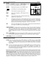
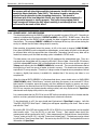
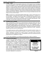
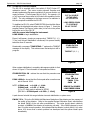
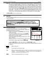
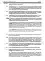
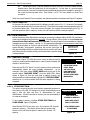

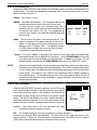
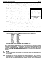
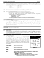
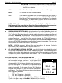
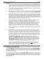

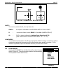

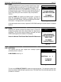

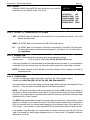

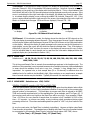


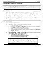
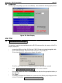
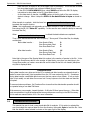
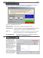
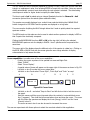
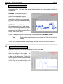
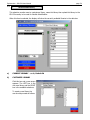

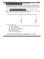
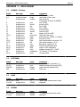

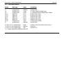
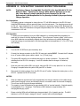
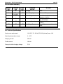
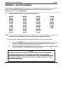
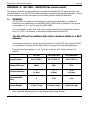
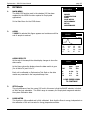
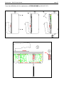

![デジタル式個人線量計のテスト結果[PDF形式]](http://vs1.manualzilla.com/store/data/006667159_3-9a7bdbbda15226a7cc4554a81ac3414d-150x150.png)