1
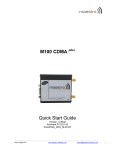
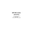
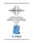
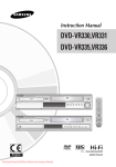
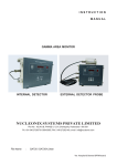
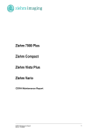
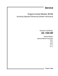
GR-100
Personal Radiation Monitor
User's Manual
Revision 1.2, Software Version 1V81, November 2004
Part Number: 32014-1
GR-100 User's Manual Revision 1.2
PROPRIETARY NOTICE
USERS ARE HEREBY NOTIFIED THAT THIS MANUAL CONTAINS TECHNICAL INFORMATION OF A PROPRIETARY
NATURE. THIS INFORMATION IS NECESSARY FOR TECHNICALLY KNOWLEDGEABLE USERS TO UNDERSTAND
SYSTEM OPERATION AND TO SATISFY THEMSELVES THAT THE SYSTEM IS PERFORMING CORRECTLY.
EXPLORANIUM ACCEPTS THAT IT IS THE RIGHT OF SUCH USERS TO BE PRIVY TO THIS INFORMATION.
HOWEVER THIS DOCUMENTATION IS PROVIDED SOLELY FOR THE BENEFIT OF OWNERS OF THE GR-100
SYSTEM AND DISSEMINATION OF THE DETAILED TECHNICAL INFORMATION PROVIDED MAY BE CONSIDERED
AS LEGALLY CONTRAVENING THE NORMAL SUPPLIER/CUSTOMER RELATIONSHIP.
UNAUTHORIZED RELEASE OF DETAILED TECHNICAL INFORMATION TO A THIRD PARTY WILL BE CONSIDERED
AS A CONTRAVENTION OF USER AGREEMENTS
SAIC/Exploranium – Proprietary
Page ii
Revision Date: November 2004
GR-100 User's Manual Revision 1.2
Table of Contents
1.0
Overview.............................................................................................................. 1
1.1
1.2
2.0
Introduction .............................................................................................................1
System description ...................................................................................................1
Operation ............................................................................................................. 4
2.1 Push button .............................................................................................................4
2.2 Battery ....................................................................................................................4
2.3 Power on .................................................................................................................5
2.4 Power off .................................................................................................................6
2.5 Updating the Background screen ...............................................................................6
2.6 Monitor mode...........................................................................................................6
2.7 Dose rate.................................................................................................................7
2.8 Alarms .....................................................................................................................8
2.8.1 Alarm Level Setting ................................................................................................8
2.8.2 Alarm Level actions ................................................................................................8
2.8.3 Search Response....................................................................................................9
3.0
Setting up the Unit ............................................................................................ 11
3.1
3.2
3.3
3.4
3.5
3.6
3.7
3.8
3.9
3.10
4.0
Search Mode ..........................................................................................................11
Setting Parameters .................................................................................................11
Setting DATE/TIME.................................................................................................12
Long Count Mode ...................................................................................................13
Return to Monitoring Mode .....................................................................................13
Remote setup.........................................................................................................14
Earphone ...............................................................................................................14
Battery charging.....................................................................................................15
Belt mounting ........................................................................................................16
Gamma alarm test ..................................................................................................16
Monitor 100U PC software ................................................................................ 17
4.1 Testing the GR-100 ................................................................................................19
4.2 Setting up parameters ............................................................................................22
4.2.1 Vibrator ............................................................................................................... 23
4.2.2 Buzzer ................................................................................................................. 23
4.2.3 LCD..................................................................................................................... 23
4.2.4 Dose Units ........................................................................................................... 24
4.2.5 Discriminator ....................................................................................................... 24
4.2.6 Alarm Threshold................................................................................................... 24
4.2.7 Info.....................................................................................................................24
4.3 Data retrieval .........................................................................................................25
4.3.1 Alarm Data Retrieval ............................................................................................ 26
4.3.2 Diagnostic Events Retrieval................................................................................... 28
4.3.3 Accumulated Dose Data Retrieval.......................................................................... 29
SAIC/Exploranium – Proprietary
Page iii
Revision Date: November 2004
GR-100 User's Manual Revision 1.2
5.0
Technical specifications..................................................................................... 32
5.1
5.2
5.3
5.4
5.5
5.6
5.7
5.8
5.9
5.10
5.11
5.12
5.13
5.14
Gamma detector and analog processor ....................................................................32
Neutron detector and analog processor ...................................................................32
Monitoring .............................................................................................................32
Searching...............................................................................................................33
Dosemeter .............................................................................................................33
Clock - Calendar .....................................................................................................33
Data storage ..........................................................................................................33
Data output ...........................................................................................................34
Display ..................................................................................................................34
Power supply option ...............................................................................................34
Connectors.............................................................................................................35
Connectors.............................................................................................................35
Environmental ........................................................................................................35
Accessories ............................................................................................................35
Appendix A Error messages...................................................................................... 37
SAIC/Exploranium – Proprietary
Page iv
Revision Date: November 2004
GR-100 User's Manual Revision 1.2
1.0 Overview
1.0 Overview
1.1
Introduction
The GR-100 is one of the most advanced, yet simple to use, personal radiation monitors deployed in
customs, security, military and emergency response applications. It has been designed to provide
accurate and reliable measurement of gamma and neutron radiation, trigger visual and audio alarms to
warn the operator, and accurately measure exposure Dose Rate over the full spectrum range. It also
aids the operator in search and location of the source of the detected radiation. The spectrum of the
source can be measured and stored in the memory. The unit is typically used as a belt-mounted monitor
or a hand-held search detector. It automatically stores alarm events date and time and dose data in its
memory for subsequent retrieval to a PC. Its simple one-button operation and user-friendly operator
interface make it truly an ideal front-line tool for a variety of users involved in detection and interception
of radioactive and nuclear materials.
1.2
System description
Standard GR-100 Personal Radiation Monitor system consists of:
•
•
•
•
•
•
•
•
GR-100 Personal Radiation Monitor Unit
Two “AA” Alkaline Batteries
Earphone With Volume Control
Belt Mounted Carrying pouch
PC Interface Cable
CD With GR-100 Monitor Software
GR-100 User Manual
Shipping Case
The following optional equipment is also available:
•
•
•
•
•
Rechargeable Nickel-Cadmium Battery
Rechargeable Nickel Metal Hydride Battery
Battery Charger and Cable Assembly
Battery Charger/PC Interface Cable Assembly
0.25 Micro-Currie Cesium137 Test Source
The GR-100 Personal Radiation Monitor is supplied in two versions:
•
•
GR-100 – equipped with CsI gamma detector
GR-100N – equipped with both CsI gamma and LiI neutron detectors
The neutron detector option must be selected at the time of purchase.
SAIC/Exploranium – Proprietary
Page 1
Revision Date: November 2004
GR-100 User's Manual Revision 1.2
1.0 Overview
The following figure shows the front and back views of the GR-100 unit.
Yellow LED lamp
indicating gamma
radiation alarm.
Red LED lamp indicating
neutron radiation alarm
Graphic LCD
showing
operating
parameters and
radiation
measurements
results
Belt clip
Cover for battery
compartment
Push button
used to select
operating
parameters and
functions
Production
label with
serial number
Earphone
jack
PC interface
connector
Audio transducer
indicating radiation
alarm and source
intensity
Rubber cover
to protect
Connector
The unit is housed in a rugged ABS plastic case designed to withstand adverse weather conditions. It
has a universal removable stainless steel clip for mounting on a variety of waist belts. The Operator
interface is facilitated by graphic liquid crystal display (LCD) and a single push button. The Radiation
alarm is displayed via one digit LED display on the top of the unit. This display is clearly visible when unit
is worn on a belt. An Alarm is also indicated with an audio beeper and a vibrator. An earphone with
volume control is provided for operation in noisy environments. It connects to an audio jack located at
the bottom of the unit under a rubber protection cap. This cap also conceals a USB connector for
interfacing the unit to a PC or/and to a Battery Charger. All functions and settings are controlled with
the button on the front panel. The Battery compartment is accessible by lifting the removable cover
plate on the back of the unit. For additional protection during operations, the unit can be inserted into a
belt mounted leather pouch. The earphone can remain connected to the unit when in the pouch. You
can set up, store, and retrieve parameters and data from the instrument by connecting it to any desktop
or notebook computer that has the GR-100 Monitor software installed.
SAIC/Exploranium – Proprietary
Page 2
Revision Date: November 2004
GR-100 User's Manual Revision 1.2
1.0 Overview
GR-100 Personal Radiation Monitor Accessories
The following figure shows the GR-100 accessories:
Belt-mounted carrying
pouch
0.25 Micro-Currie
Cesium137 Test
Source
PC interface cable
Earphone with Volume Control
SAIC/Exploranium – Proprietary
CD With GR-100
Monitor Software
Page 3
Revision Date: November 2004
GR-100 User's Manual Revision 1.2
2.0 Operation
2.0 Operation
2.1
Push button
The push button is used as a function selection switch. There are 3 basic ways to use this button:
•
SHORT PRESS – Short depression of the button, lasting more than 0.1 seconds but less then 1
second.
•
LONG PRESS – Long depression lasting, lasting more than 1 second but less then 2 seconds.
•
HOLD – Press and hold for more than 5 seconds.
Activation shorter than 0.1 sec is called SPIKE and is ignored by the system. Activation longer than 2
seconds starts the Switch OFF procedure, but if activated for less than 5 seconds it changes to LONG.
2.2
Battery
The unit operates off a single AA battery. The system recognize two types of batteries – rechargeable or
non-rechargeable. Non-rechargeable means alkaline battery and two types of rechargeable batteries can
be used: Nickel-Cadmium (NiCd) or Nickel Metal Hydride (NiMH).
The battery is loaded by removing the battery cover – use a finger-nail or coin in the groove in front of
the slot on the rear to lever the battery door open. Insert the battery in the battery compartment, being
sure to place the bottom of the battery on the spring and the top to the brass terminal. Seat the battery
firmly in place above the removal strap then clip the battery cover in place.
NOTE: All measured data is stored in non-volatile memory and they remain in the memory even if the
battery is removed after the correct power-down sequence.
CAUTION: If you remove the battery while the GR-100 is in operation, your data will be lost. Please use
the correct power-down sequence before removing the battery to ensure that data will not be lost.
NOTE: The time/date information will be lost if the battery is removed for more than one minute.
Therefore, it is recommended to replace battery within one minute to avoid the time and date reset.
First prepare the new battery to be installed. Then remove the old battery and quickly replace it with the
new one. If you experience any problem with the new battery, reinstall the old battery back until the
problem is resolved. The old, nearly discharged battery will not be sufficient for operation of the
equipment, but it will keep the time and date for a while. If the time and date is lost, it can be easily
reset manually upon first power-up, or by the PC when connected.
SAIC/Exploranium – Proprietary
Page 4
Revision Date: November 2004
GR-100 User's Manual Revision 1.2
2.3
2.0 Operation
Power on
To power on the GR-100, make a LONG press with the front panel push button. The STARTUP screen is
displayed for approximately 5 seconds:
•
•
•
GR-100 is the instrument model number
1V7 is the current firmware version installed in the unit
#3284 is the unit’s serial number
EXPLORANIUM
GR-100
1V7
#3284
During the start-up the unit performs a series of internal self-testing procedures and verifies that the
alarm indicators are functioning. You can observe the following:
•
•
•
•
BUZZER beeps (if enabled)
RED light flashes as a lamp tests
YELLOW light flashes as a lamp tests
VIBRATOR vibrates (if enabled)
The unit recognizes during the start-up procedure if the battery was replaced and proceeds with
additional tests and set-up procedures. During those tests you have to select the battery type to assure
proper operation.
The SHORT press advances display to the next battery type selection
(RECHARGEABLE). The LONG press confirms the selected battery type and
continues the power-up sequence. The next warning will be displayed if the
remaining capacity of the battery is less than about 5 – 10 %. It is possible to
continue using the unit for a few hours, but it is recommended to change or
charge battery soon.
NOTE: To save remaining battery power, the backlighting cannot be activated
when LOW BATTERY is displayed.
If you continue using the unit and the battery becomes completely discharged,
the following screen is displayed and the unit is turned OFF.
If battery was not replaced within one minute, or after the first power-up, the
Set Date/Time screen is displayed before battery selection is requested.
To set the date, SHORT press changes the year (YY) and LONG press confirms
the selected setting and moves the cursor to month (MM) and than to day (DD).
After confirming the Day setting, the screen changes to time setting.
The setting of the hours (HH) and minutes (MM) are analogous, the seconds are
only displayed but it is not possible to set them. The procedure continues via
selecting the battery as described above.
SAIC/Exploranium – Proprietary
Page 5
NEW BATTERY
SELECT TYPE
NON-RECHARGE
LOW BATTERY
PRESS MODE
BATTERY
DISCHARGED
SWITCH OFF
SET DATE/TIME
YY
00/01/01
SET DATE/TIME
HH
00:00:00
Revision Date: November 2004
GR-100 User's Manual Revision 1.2
2.4
2.0 Operation
Power off
To power the unit OFF press HOLD (press button and hold for about 5 seconds) until the following
sequence of displays is seen and the power goes OFF. Note that if you release the button at any point
before power-off is completed, the system will take it as a LONG press and it will go back to the
SETTING screens.
NOTE: If powering down from other displays, the first message appears according to the LONG press
and after 5 seconds the power will go OFF.
SEARCH
2.5
SWITCH OFF
3
SWITCH OFF
2
SWITCH OFF
1
Updating the Background screen
After initial start up the system must accumulate a radiation background level to
assess the local background. Be sure to do this while at a sufficient distance from
possible radiation sources. The display shows a 5 second countdown (5, 4, 3, 2, 1)
during this process.
12:57
UPDATING
BACKGROUND
4
At the end of this period the local background is stored in memory. Later, the background level is
updated regularly every 10 seconds and used for Alarm Level calculations.
2.6
Monitor mode
After the STARTUP screen is displayed for a few seconds and UPDATING BACKGROUND is completed,
the unit goes to monitoring mode and the MONITOR screen is displayed.
SAIC/Exploranium – Proprietary
Page 6
Revision Date: November 2004
GR-100 User's Manual Revision 1.2
2.0 Operation
NOTE: In normal background conditions (absence of radiation sources), the count rate should be
between 5 and 25 cps and the dose rate about 50 - 250 nGy/h, 50 - 250 nSv/h or 5 - 25 mR/h.
The battery status icon is fully black when battery is fully charged. As the battery capacity goes down
the black filling decreases to the right-hand side. The icon is “empty” if the capacity drops down to
about 10 %.
The YELLOW LED light flashes faintly every three seconds to show the system is operational and battery
is OK. If battery is low, the RED LED light starts flashing.
2.7
Dose rate
The GR-100 is an instrument that accurately displays the computed Dose-Rate over the full spectrum
range. The unit is calibrated so that whether the source is Americium, Cesium, Cobalt or any other
isotope, the Dose Rate computation is accurate. This is achieved by using an internal spectrometer
analysis system that compensates for spectral influence of the Dose Rate. The Dose Rate is shown in
both Monitor and Search modes in the bottom part of the display.
Note: The displayed Dose Rate is a 10 second moving average. It means that the value is renewed
every second, but it is calculated from the signal measured during the last 10 seconds.
Current Dose Rate can be measured in three different units:
•
Gy/hr (Grays per hour) units are used mostly in Europe for radiation Dose Rate measurements.
•
R/hr (Roentgens per hour) units of exposure to radiation are used mostly in North America.
•
Sv/hr (Sievert per hour) units are used for equivalent Dose Rate when the person’s health risk is
assessed.
The measurement range is 0.01 – 100 µSv/hr, covering the range from very low background to the
danger level. When the actual dose rate is higher than 100 µSv/hr, the message OVERLOADED is
displayed instead of the dose rate value. The display returns to show the dose rate when radiation level
drops below 100 µSv/hr.
The calibration point for dose rate is defined as the center of the gamma detector, which is 3 cm from
the top edge of the unit (in the middle of display), 1 cm from the right edge and 1.3 cm under the face
side. The irradiation direction is from the side opposite the display.
The Dose Rate is accumulated in the GR-100 memory during operation in Monitoring or Searching mode
and stored every hour, or when the unit is powered down. The results can be downloaded to a PC and
saved. The Dose Rates are always stored in nSv/h units no matter what selected units are set for
viewing on the display.
SAIC/Exploranium – Proprietary
Page 7
Revision Date: November 2004
GR-100 User's Manual Revision 1.2
2.8
2.0 Operation
Alarms
For normal use the unit is operated in the MONITOR mode. In this mode, the signal is analyzed for
alarm conditions and the results are updated every second.
2.8.1 Alarm Level Setting
After start-up a 5 second average of the local radiation background is computed and stored in memory.
This is the Start Background. The system automatically updates this background every 10 seconds using
a special algorithm that creates an accurate representation of the local background. This is referred to as
the Local Background.
The Alarm Threshold is a parameter in the unit’s memory that you can set. The unit automatically sets
the Gamma Alarm Threshold by applying the Gamma Parameter that you set via the PC Monitor 105
program to the background. The Gamma Alarm threshold setting represents the number of standard
deviations (Sigma) of the local background radiation signal by which the measured signal must exceed
the background signal to trigger an alarm. The gamma threshold is constantly adapting to varying
background conditions.
The local background is constantly updated unless an alarm occurs, in which case the updating is
suspended until the alarm is cancelled and Monitoring mode is restarted. It is strongly recommended
that you step back from the source before switching to Monitor mode to make sure the background is
truly reflective of only the local radiation level and not the anomalous level due to the detected source.
Also note that once the alarm threshold is set using this technique, the unit is usable in any local
radiation setting without further need for readjustment. The alarm level is automatically changed to
adapt to local radiation conditions.
2.8.2 Alarm Level actions
The GR-100 unit is typically worn on a belt. You are alerted to an alarm by an audio beep and/or
vibration action, depending on the system settings selection. In alarm condition, you can glance down at
the unit and see the flashing LEDs through the transparent windows as a visual reinforcement that an
alarm has occurred.
The following indications are present when an alarm occurs:
•
The AUDIO transducer beeps in a warning mode of 5 triple-beeps that are approximately 2 secs
apart.
•
The appropriate LED lights up (YELLOW=Gamma, RED=Neutron) in a
flashing mode ones per second.
•
The VIBRATOR is activated 5 times, provided it is enabled.
•
The LCD screen shows:
SAIC/Exploranium – Proprietary
Page 8
GAMMA ALARM
PRESS BUTTON
44.4 µR/h
Revision Date: November 2004
GR-100 User's Manual Revision 1.2
2.0 Operation
In this case the unit indicates that a GAMMA alarm has occurred. The displayed dose rate is the
maximum value measured during the period the alarm message is on the screen. In the alarm
condition, the displayed value is obtained from 1 second measurements. The short integration time is
used to learn about the dose rate maximum to make searching (in Search Mode) the radiation “hot spot”
easy. The real dose rate, the measure of the health hazard, is stored in the memory as dose history.
Press SHORT to go to the SEARCH MODE. After
pressing SHORT, the following screen is displayed:
As noted above, in the SEARCH mode the count
rate, dose rate and audio tone are used to
accurately locate the source of radiation. The
higher value or the higher frequency of beeping
means that the detector is closer to the source.
A SHORT press of the button at any time in the
SEARCH mode will return the unit to the MONITOR
mode. If no action is taken in SEARCH mode for
15 minutes, the unit will return to the monitoring mode automatically.
2.8.3 Search Response
The following response is obtained in the SEARCH mode:
•
As the unit approaches radioactive material the COUNT display (234 above) increases to show
that the radiation intensity is increasing.
•
If any neutron radiation is present, the neutron data will be displayed in counts/second.
•
As the radiation intensity increases, the AUDIO frequency will increase proportionally (if enabled),
thus making it easy to locate the source in an “eyes-free” manner.
•
The audio signal responds to radiation from just above the alarm threshold level to very high
level (the count rate of 2000 cps) in progression of beep frequency. The frequency of beeps is
proportional to the count rate in non-linear manner. Using this method, the response to low
radiation levels is enhanced to enable the search for distant or shielded sources. The beep
frequency remains constant above 2000 counts per second.
SAIC/Exploranium – Proprietary
Page 9
Revision Date: November 2004
GR-100 User's Manual Revision 1.2
3.0 Setting up the Unit
3.0 Setting up the Unit
To access the unit set-up screens from the MONITOR mode, do a LONG press. The sequence starts with
SEARCH. In any of the following screens a SHORT press advances to the next selection and the LONG
press activates the selected function or parameter.
•
SEARCH - switches to the SEARCH mode when the unit is not in alarm.
•
SETTINGS – enables activation of the audio beeper, vibrator and backlight. SHORT press toggles
between ON or OFF.
•
DATE/TIME – enables date and time setting.
•
LONG COUNT – enables measurement over an extended period of time.
•
MONITOR – returns back to the monitoring mode.
3.1
Search Mode
While in the monitor (MON) display, press LONG until you see:
SEARCH
Release the button when the search screen is displayed. Subsequent LONG
press will select the search mode, the following screen will be shown briefly and then
the full SEARCH screen will be displayed.
3.2
SEARCH
SELECTED
Setting Parameters
A LONG press in the monitor mode followed by a SHORT press brings on the SETTINGS
screen:
SETTINGS
Setting mode is entered with another LONG press:
The first screen that follows is used to set the beeper ON or OF:
SETTINGS
SELECTED
SETTINGS
BEEPER ON
SAIC/Exploranium – Proprietary
Page 11
Revision Date: November 2004
GR-100 User's Manual Revision 1.2
3.0 Setting up the Unit
The SHORT press toggles the beeper setting between ON and OFF, the LONG press confirms the
selected setting and advances the screen to the next parameter. If there is no action for 15 seconds
during the parameter setting procedure, the unit returns to the monitoring mode. The procedure
proceeds with setting the following three parameters:
•
BEEPER ON / OFF – this determines whether the internal audio beeper (or earphone) is active
for alarms and search. The beeper cannot be turned off if the vibrator is also turned off. One of
the two alarm indicators must always be activated.
•
VIBRATOR ON / OFF – some users want a covert alarm capability so they want to use the
vibrator rather than the beeper. It is recommended placing the GR-100 into the breast pocket in
this case. The vibration may not be noticed when the unit is belt mounted. However the
vibrator uses a lot of electrical power, thus shortening the battery life. This function is not
essential and therefore, it is recommended that the vibrator be set to OFF to conserve battery life
•
BACKLITE ON / OFF – In low light conditions the backlight makes the display substantially
more visible. If ON, the display is illuminated during switching ON procedure; in case of ALARM,
during SEARCH mode operation and 10 seconds after any button activation. During backlighting
the battery drain is increased about 10 times. Normally it decreases the battery life 2 or 3 times
according to the ratio between MONITOR and SEARCH mode. In the rare occasions that this
feature is actually required it can be temporarily enabled as described below. So normally it is
recommended that this function be OFF.
After confirming the backlight status selection via LONG press, the unit resumes the monitoring mode.
3.3
Setting DATE/TIME
A LONG press in the monitor mode followed by two SHORT presses brings on the
DATE/TIME setting screen:
Then LONG press confirms the selection:
DATE/TIME
DATE/TIME
SELECTED
Follow the same procedure as in 2.3 to set correct date and time:
SET DATE/TIME
YY
00/01/01
To set date, SHORT press changes the year (YY) and LONG press confirms the
selected setting and moves the cursor to month (MM) and than to day (DD). After
confirming the Day setting, the screen changes to time setting.
SET DATE/TIME
HH
00:00:00
The setting of the hours (HH) and minutes (MM) are analogous, the seconds are only displayed but it is
not possible to set them. The SHORT press changes the value, the LONG confirms it. After confirming
the minutes via LONG press the unit returns to monitoring mode.
SAIC/Exploranium – Proprietary
Page 12
Revision Date: November 2004
GR-100 User's Manual Revision 1.2
3.4
3.0 Setting up the Unit
Long Count Mode
From the MONITOR display press LONG and than three times SHORT to bring
the LONG COUNT setting screen on:
LONG COUNT
Press LONG to confirm the selection:
LONG COUNT
SELECTED
This activates the LONG COUNT feature and starts the counting cycle. The LONG COUNT screen is
similar to the monitor screen except the MON symbol is replaced with the counting time period.
This mode of operation allows you to make longer time of measurement to
obtain higher sensitivity and more precise results for low level radiation in
constant radiation field. You can terminate the counting cycle at any time by
pressing LONG. The following screen appears after termination of the counting
period:
•
•
•
•
•
•
3.5
12:57
N 0
1
234
44.4 µR/h
G
N
G - means column with the gamma data
28620
2
N - means column with the neutron data
31 0.00
901
sec
The first data row (28620, 2) indicates the total number of counts per
the total counting time period for the respective gamma and neutron
detector.
The second data row (31, 0.00) indicates the count rate with the respective gamma and neutron
detector.
The third data row (901 sec) indicates the total counting time period in seconds.
The SHORT press resumes the standard monitoring mode again.
Return to Monitoring Mode
If you enter the function selection routine by mistake, you can return to the
monitoring mode by pressing SHORT four times.
MONITOR
You can select the monitoring mode by pressing LONG:
MONITOR
SELECTED
Consecutive SHORT presses move the selection in a loop sequence: SEARCH –
SETTINGS – DATE/TIME – LONG COUNT – MONITOR until you confirm one of the
selections. If no action is taken by the operator for 15 seconds, the unit reverts back to the monitoring
mode automatically.
SAIC/Exploranium – Proprietary
Page 13
Revision Date: November 2004
GR-100 User's Manual Revision 1.2
3.6
3.0 Setting up the Unit
Remote setup
The GR-100 is supplied with an external RS-232 serial cable that plugs into a connector on its base. The
other side of the cable is connected to the serial port on a PC running the Monitor 100U Remote Control
Software supplied by Exploranium on the CD included with the unit. Operating instructions for this
software are described in Section 4 of this manual. The software allows you to set-up remotely all
system parameters and operating functions and retrieve stored data.
3.7
Earphone
The earphone supplied with the unit can be used in noisy environment, or in covert operations. The
earphone can be plugged into a special connector on the base of the unit after lifting the rubber cover.
The earphone jack is located under the
rubber cover on the left-hand side. The
right-hand side is fixed to avoid the loss of
the cover. When connected, it
automatically disables the internal audio
beeper.
NOTE: The BUZZER must be enabled for
this function to work.
When the earphone is unplugged the unit
automatically reverts to internal audio
functions.
Figure Earphone Connection
If the GR-100 is used with the belt mounted leather carrying pouch, connect the
right-angle earphone plug as shown in the figure above. Hold the cable along the left
side of the case and insert the unit into the leather pouch with the cable running
along the side of the pouch as shown in the next figure. There is space provided
inside the pouch for the connector to fit. GR-100 can be taken out of the pouch
without disconnecting the earphone.
Earphone Used
in Belt Pouch
SAIC/Exploranium – Proprietary
Page 14
Revision Date: November 2004
GR-100 User's Manual Revision 1.2
3.8
3.0 Setting up the Unit
Battery charging
Rechargeable batteries and the charger are available as an optional equipment Either Ni-Cd or Ni-MH
batteries can be charged inside the unit. The 110 VAC/12 VDC (or 220 VAC/12 VDC) adapter connects to
the mini-USB jack at the bottom of the unit using a separate cable supplied with the option.
CAUTION: Using any other cable can cause fatal damage to the instrument!
Open rubber cover located on the bottom of the GR-100 and insert power cable adapter to the mini-USB
jack in the centre. Handle the cover on its left hand side where the earphone connector is located. The
right-hand side is fixed to avoid the loss of the cover. You must be sure that proper battery type is
selected! If not, remove the battery, check its type, re-install it and switch the unit ON. The request for
battery type selection appears during the start up procedure after a new battery was installed.
Connecting the AC power pack to an electrical outlet begins the charging cycle. Battery charging
proceeds regardless of whether the unit is turned ON or OFF.
NOTE: This function is disabled in the PARAMETERS SETTING mode!
IMPORTANT: Never connect external power to the GR-100 if the battery is not correctly placed in the
battery compartment!
While charging the battery, the yellow LED is ON continuously to indicate
charging is in progress and the LCD displays the following screen:
CHARGING ON
TIME
0 min
1.40V 221mA
The charging time in minutes is displayed in the middle row; the voltage on the batteries and the
charging current is shown in the bottom row. Normal battery charging takes out about 8 hours, from
fully discharged to fully charged, for the rechargeable batteries specified. When
BAT. CHARGED
the battery is charged to about 95 % capacity, charging goes to the trickle mode
TIME 468 min
and the yellow LED starts flashing once every 10 seconds. The display indicates
1.40V
end of charging but if the unit is not disconnected, the trickle charging continues
every ten seconds preserve full battery capacity.
After disconnecting the power adapter the GR-100 returns to previous point of operation. From
MONITORING or SEARCH mode, it goes to UPDATING BACKGROUND and then to MONITORING mode.
If the unit was OFF before charging started, it switches OFF when charging is completed. If charging
was started from the display BATTERY DISCHARGED SWITCH OFF or LOW BATTERY message, the Start
up procedure checks the battery voltage.
Note: Charging of the battery must be done in an area within temperature range from 10°C to 30°C.
SAIC/Exploranium – Proprietary
Page 15
Revision Date: November 2004
GR-100 User's Manual Revision 1.2
3.9
3.0 Setting up the Unit
Belt mounting
The GR-100 is equipped with a clip for breast pocket or belt mounting, and is also furnished with a
leather carrying pouch, which can also be attached to the belt. If GR-100 is used with the leather
carrying pouch only, the clip should be removed from the unit for smooth insertion into case.
If the earphone is used for covert operations with belt mounted leather carrying pouch, connect the plug
and insert GR-100 into the leather pouch with the cable on the left-hand side of the unit and close the
case. There is space enough for the connector inside the case. It is then easily possible to take out the
GR-100 from the case and follow the display during SEARCHING without disconnecting the earphone.
3.10 Gamma alarm test
For fast and easy alarm test, use the reference source included with the unit. Run GR-100 in the monitor
mode and move the reference source close to the back right-hand side of the instrument. GR-100 must
show GAMMA ALARM within 2 seconds.
NOTE: Used reference source has very low activity (0.25 mCi = 9.25 kBq) of Cesium-137. It is not
classified as a controlled radioactive source. The source is also encapsulated and therefore handling it by
the operator for testing purpose is safe.
SAIC/Exploranium – Proprietary
Page 16
Revision Date: November 2004
GR-100 User's Manual Revision 1.2
4.0 Monitor 100U PC software
4.0 Monitor 100U PC software
The Monitor 100U is a program for the remote control of the GR-100 Personal Radiation Monitor. This
software permits you to set-up the operating parameters in the GR-100 from a PC, as well as retrieve
internal data for analysis and record keeping.
The Monitor 100U software is supplied on the CD ROM that is included with the GR-100 unit. To launch
the software:
1. Copy the directory “Monitor100U” from the CD to the desired location on your PC.
2. Create a shortcut to the Mon100U.exe file on your desktop for easier software launching.
3. With the serial cable supplied with the unit, connect one side of the cable to the serial port at the
back of your PC. Note the serial port number.
4. Pull the left-hand side of the rubber cover on the bottom of the GR-100 to gain access to the
connectors. The right-hand side of the rubber cover is affixed to the case to prevent accidental
loss of the cover. Connect the mini-USB connector of the serial cable to the mating mini-USB jack
on the unit.
Caution: Use only communication cable supplied with the unit. Using any other USB cable can
cause fatal damage to the GR-100 or the PC.
5. Turn the GR-100 ON. The message “REMOTE” will appear on the screen to confirm that the unit
is connected to the PC.
6. Start the program by double-clicking the Mon 105 icon (you can also run the Mon105.exe from
the CD directly). The Main Menu screen appears.
SAIC/Exploranium – Proprietary
Page 17
Revision Date: November 2004
GR-100 User's Manual Revision 1.2
4.0 Monitor 100U PC software
Four menu items are available in the menu bar, three of which are for controlling the unit: Tests, Setting
and History. The Exit button stops the program. To switch among the Tests, Setting and History screens,
you have to return to the main menu first by clicking on the Main Menu Button.
Changing COM ports
If you start the Monitor 105 program before the unit is
connected to the PC, communication problems between the
PC and the unit may occur. In this case the program displays
an error message and stops the operation. Close the program
and restart it again after the GR-100 has been connected to
the PC.
If the GR-100 unit is connected to the COM 1 port on the PC,
it will start communicating with the PC automatically. If it is
connected to a different port, an error message will appear,
and you must do the following:
1. Close the error message window.
2. Click on COMx in the menu bar and select the correct
COM port in the Communication Port pop-up window.
3. Click on Main Menu button to return to the main menu
screen.
SAIC/Exploranium – Proprietary
Page 18
Revision Date: November 2004
GR-100 User's Manual Revision 1.2
4.1
4.0 Monitor 100U PC software
Testing the GR-100
Clicking the Tests button opens the HW Tests screen for providing a number of equipment tests. The
tests can be useful for advanced users or for service technicians.
Tests are provided via buttons in the main part of the screen (labeled Tests). During a test a button’s
label changes to STOP to enable interruption of the procedure. The HW Tests screen has the following
fields and controls:
• White field
(upper left)
– Shows the system messages for the provided operations.
• Gray field
(upper right)
– Shows the measured data in graphical form. The color for this field turns yellow
for gamma data and blue for neutron data.
• Single/
Repeat
– Allows tests to be done once or every second.
SAIC/Exploranium – Proprietary
Page 19
Revision Date: November 2004
GR-100 User's Manual Revision 1.2
4.0 Monitor 100U PC software
• UART
– Tests communication with the GR-100 and receives data from it.
• Buzzer
– Causes GR-100 to beep.
• Vibrator
– Causes GR-100 to vibrate.
• Gamma LED
– Tests the yellow gamma LED.
• Gamma LED
– Tests the red neutron LED.
• Mode
– Checks the status of the button action on the GR-100. The status of the button
action is displayed:
-
NO Key means an absence of any action.
SPIKE means activation shorter than 0.1 second
SHORT is between 0.1 and 1 second
LONG is between 1 and 2 seconds.
Activating the button for longer than 2 seconds has no meaning (unless it is
held for 5 seconds to switch off the GR-100).
• Temperature
– Displays the actual value taken from the internal thermometer on the GR-100.
• Battery
– Displays the actual voltage of the GR-100 battery via its internal voltmeter.
Click the RECORD button to store charging data. The Open File to Save
Charging Battery dialog box appears. Enter the file name and folder for storage
data. The data is stored in text form; each measurement refers to one row
with the time, the voltage [V] and the actual battery current [mA] (for
instance: 12:10:00 1.35 210).
• DAC0/DAC1
– Sets the discriminator channels for gamma (DAC0) and neutron (DAC1). The
button next to it allows you to display the values in steps or mV. This button
also has a third option called saw tooth for special DAC0/DAC1 tests.
• Counters
– Reads and displays the number of pulses in the gamma and neutron channels
and the live time. These measurements are provided every second. On first
check the labels T0, T1, T2 and neutr are displayed instead of values.
You can save the values to a file by first clicking the Repeat button. The “Open
File to Save COUNTERS” dialog box appears. Enter a file and folder. When
finished the test, click the STOP button. The data is stored in text format with
each measurement as one row containing three numbers corresponding to the
number of counts in the gamma channel (T0), neutron channel (T2), and life
time in milliseconds (which would be less than 1000 since data is measured at
1 second intervals).
• Read RTC
– Reads the real-time clock on the GR-100 and displays the data in the next field.
• Send RTC
– Reads the real-time clock on the PC and writes it to the GR-100. The data is
displayed in the previous field.
SAIC/Exploranium – Proprietary
Page 20
Revision Date: November 2004
GR-100 User's Manual Revision 1.2
4.0 Monitor 100U PC software
• LCD
– Fills the GR-100 display with test text and allows you to change the contrast of
the LCD display with the arrows buttons. You can see the results on the
display. TEMP displays the temperature to which the contrast is calculated.
• Backlite
– Enables or disables the backlight of the LCD display for test purposes. It has no
effect on the equipment settings after exiting the LCD test screen.
• Status
– Displays the following info about the processor:
•
•
•
•
•
•
the total working time
number of loading defaults
number of LOW count situations
number of HIGH count situations
number of high current situations
serial number of the processor board
• RAM 2 kB
– Tests the integrity of the RAM memory with the capacity of 2 kB. This test lasts
about 7 seconds.
• EEPROM 8
kB
– Tests the integrity of the EEPROM memory with the capacity of 8 kB. This test
lasts about 8 seconds and deletes all ALARM/DIAGNOSTIC/DOSE records in the
memory.
• Spectrum
– Allows remote access:
1. Set the ADC GAIN for the gamma detector (1, 2 or 4 next to G-ADC Gain
button). This will activate the LLD Spectrum or MCA Spectrum buttons.
2. Click the Gamma/Neutron button to select the status of the Gamma
detector or the Neutron detector
3. Set the time of measurement (1 to 60 seconds for LLD or any time for
MCA) in the field Time [sec.]).
The first method (LLD) is provided by moving the discrimination level. It takes
time but in some cases it can be very useful since the measurement is provided
the same way as standard measurement. Pressing the LLD Spectrum button
activates this function. The total measurement time is 40 times longer because
each channel must be measured separately.
The measured data is displayed on-line in the upper right field of the PC
screen. When the gamma detector is used the field color turns yellow. With
the neutron detector it turns blue.
• OFF-LINE
Utilities
– Lets you measure the LLD Spectrum for longer than 60 seconds. The
procedures are started from the GR-100 G-Spectrum or Maintenance Mode,
which lets the GR-100 operate without communication to the computer while
the measured spectra are stored in the GR-100’s memory. After finishing the
measurement the GR-100 goes to Monitor Mode. The latest results can be
transferred into the PC after connecting via serial cable and starting the
Monitor GR100 software.
SAIC/Exploranium – Proprietary
Page 21
Revision Date: November 2004
GR-100 User's Manual Revision 1.2
4.0 Monitor 100U PC software
Get OFF-LINE Data in the Tests window takes the measured data from the
equipment memory, automatically recognizes the type of measurement, and
displays it in the upper right field of the PC screen.
4.2
Setting up parameters
To modify setup parameters, click the Setting option in the menu bar. The Setting screen appears.
This screen has a frame containing a series of buttons and data fields for the User Settings and three
separate buttons to the right of the frame for displaying and saving the selected sets of settings. The
unit comes with a set of standard parameters and settings loaded at the factory as default settings.
These settings are permanently stored in the memory and can be recalled at any time by clicking on the
Display Default Settings button.
SAIC/Exploranium – Proprietary
Page 22
Revision Date: November 2004
GR-100 User's Manual Revision 1.2
4.0 Monitor 100U PC software
You can change some of the settings to suit your preference or to adapt the instrument to unusual
conditions at the site of the measurement. These settings are called User Settings and they can be saved
by clicking the Save User Settings button to create a user specific profile. Both the default and user
settings are stored in the unit’s memory. The user settings can also be recalled to the screen by clicking
the Display User Settings button. The User Settings can be subsequently modified and saved again.
However, the new settings overwrite the previous User Settings. Only one set of User Settings are
allowed to be stored in the unit. When the User Settings are saved, the unit retains them until they are
changed again from the PC. The saved User Settings will be activated every time the unit is turned ON.
The default settings are displayed in black. Any change made to the default parameters causes the
settings to change to red color to alert you that parameters have been changed. Similarly, the settings
color changes to red when the user settings are changed. To revert back to the default settings, you
must recall the default settings to the screen first and then save them as the User Settings. The unit
always works with the settings stored in the user settings location in the memory.
The User Settings frame in the Setting screen contains seven sub-frames with grouped controls for:
Vibrator, Buzzer, LCD, Dose Units, Discriminator, Alarm Threshold, and Info.
4.2.1 Vibrator
The ON/OFF button in the Vibrator frame allows you to enable or disable the vibrator action when an
alarm occurs. Clicking on the button toggles between ON and OFF setting. While the vibrator action
increases the electrical current consumption by a factor of ten when it is running, it has no effect on the
battery life in the absence of alarms.
4.2.2 Buzzer
The ON/OFF button in the Buzzer frame allows you to enable or disable the audio beeper indicating an
alarm condition. Clicking on the button toggles between ON and OFF setting. This setting also affects the
audio beeper action in the Search mode and the output to the earphone. The Beep ON/OFF button in
the Buzzer frame enables or disables an audio beep that is used to confirm action of the main push
button on the unit. The beep function is useful to inform the operator that his mode selection has been
successfully executed.
4.2.3 LCD
The Backlite ON/OFF button in the LCD frame enables or disables the screen backlighting. The backlight
is used to improve the display readability in poor lighting conditions. The display backlight increases
current consumption by ten times. The battery life is significantly shortened when the backlight is
activated. You should exercise caution when activating the backlight.
The display contrast changes with the ambient temperature at the measurement site. The unit
automatically adjusts contrast to maintain the best viewing conditions. For this purpose, the unit
monitors the outside temperature and calculates the required correction for the contrast setting. The
temperature is displayed in the bottom field of the LCD frame. The coarse contrast setting is set at the
factory and cannot be changed by the user. However, you can make minor adjustments by changing the
setting in the Contrast Fine window. The Contrast Fine setting range is from 0 to 64. Zero corresponds
to blank screen and 64 to completely black screen. The average setting is 32.
SAIC/Exploranium – Proprietary
Page 23
Revision Date: November 2004
GR-100 User's Manual Revision 1.2
4.0 Monitor 100U PC software
4.2.4 Dose Units
The operator can select his preferred units for the dose measurement in the Dose Units Frame by
clicking on the appropriate selection icon. The Gy/hr (Grays per hour) units are used mostly in Europe
for radiation dose rate measurements. The R/hr (Roentgens per hour) units of exposure to radiation are
used mostly in North America, and the Sv/hr (Sievert per hour) units are used for equivalent dose rate
when the person’s health risk is being assessed.
4.2.5 Discriminator
The Gamma and Neutron settings in the Discriminator frame are not accessible to the user. These
settings determine the detection windows and are established during the factory set-up and calibration.
4.2.6 Alarm Threshold
In the Alarm Threshold frame, you can select individual settings for the gamma, neutron and danger
radiation levels at which an alarm is triggered. The Gamma threshold setting represents the number of
standard deviations (Sigma) of the local background radiation signal by which the measured signal must
exceed the background signal to trigger an alarm. The allowed range for this setting is from 0.0 to 9.9.
However, zero setting will completely disable the alarm function. This feature is used for testing and
diagnostics. The gamma threshold is constantly adapting to varying background conditions. Default
value for the Gamma setting is 5.0. If you attempt to delete the gamma threshold setting or to enter a
setting that is outside of the allowed range, a warning message is displayed. Acknowledging the warning
message will reinstate the default setting.
The Neutron alarm threshold setting represents the number of neutrons detected in one count period (6
sec) that the measured signal must exceed to trigger an alarm. The neutron threshold is a fixed value,
unlike the gamma threshold that changes proportionally to changing background. Using a fixed neutron
threshold is possible because the background neutron count rate is very low and it is not varying
significantly from one location to another. If you attempt to delete the neutron threshold setting or to
enter a setting that is outside the allowed range, a warning message is displayed. Acknowledging the
warning message will reinstate the default setting.
The Danger threshold settings represent the value that the signal must exceed to trigger a Danger
Alarm. The default setting for gamma radiation is 10 mSv/h. The default setting for neutron radiation is
10 counts per one counting period of 6 seconds. If you attempt to delete the danger threshold setting or
to enter a setting that is outside the allowed range, a warning message is displayed. Acknowledging the
warning message will reinstate the default setting.
4.2.7 Info
The Info frame contains information about the unit that is either entered at the factory or constantly
measured by internal sensors. This information cannot be changed. The first two fields display the unit’s
serial number and the current firmware version respectively. The third field displays the internal
temperature, and the forth shows the current battery voltage indicating the current state of the battery.
The bottom field in the Info frame displays the current date and time in the unit. This date and time can
be re-set to synchronize with the local date and time running in the PC. Clicking on the Set Date/Time
SAIC/Exploranium – Proprietary
Page 24
Revision Date: November 2004
GR-100 User's Manual Revision 1.2
4.0 Monitor 100U PC software
button next to the Date/Time field synchronizes the unit clock with the PC clock and subsequent clicking
on the Set User Settings re-sets the time and date in the unit (Stores the new synchronized clock data).
4.3
Data retrieval
GR-100 stores in its memory all alarm, dose and diagnostic events data acquired during its use. This
data can be downloaded to a PC for viewing, printing and saving for subsequent evaluation or electronic
distribution. Clicking on History in the menu bar in the Main Menu opens the History screen that is the
starting point for data retrieval.
The History screen has a large white window that is used to display the data that has been retrieved
from the unit. The buttons below the white window enable you to read various type of data from the
unit’s memory, display it in the window, print a hard copy of the displayed data, save the data to a
selected folder in your PC, and erase the data from the unit’s memory.
The buttons contained within the ALARMS/DIAGNOSTC frame are used to handle the alarm and
diagnostic data, and the buttons in the DOSE frame are used for dose data only. The Print and Save to
File buttons in both frames can be toggled between ENABLE and DISABLE settings. When the Print
button is ENABLED, pressing Read Alarms will send the alarm data to the printer and pressing Read
Diagnostic will print the diagnostic data. Similarly, when the Save to File button is ENABLED, pressing
Read Alarms or Read Diagnostic will save the alarm or diagnostic data respectively to a file in the
SAIC/Exploranium – Proprietary
Page 25
Revision Date: November 2004
GR-100 User's Manual Revision 1.2
4.0 Monitor 100U PC software
directory where the Monitor 100U program resides. Pressing Clear Alarms/Diag will erase both alarm and
diagnostic data from the GR-100 memory. Buttons in the DOSE frame function in the same manner for
the dose data.
4.3.1 Alarm Data Retrieval
Clicking on the Read Alarms button in the History screen activates the alarm data download from the
unit to the PC. The alarm data is displayed in the chronological order. All alarms that have occurred since
the last time the alarm memory was cleared are displayed. The data will appear on the screen as shown
bellow.
The alarm display has two sections: the header information and the actual alarm data. The header
contains: Two write and read memory location numbers, Date, Time, Unit’s Serial Number, and Current
Firmware Version.
Alarms Registered by GR-100
02A0 0010 03/10/27 19:35:15 3206 1V7j 0
Memory
Locations
Date
SAIC/Exploranium – Proprietary
Time
Serial
Number
Firmware
Version
Page 26
Revision Date: November 2004
GR-100 User's Manual Revision 1.2
4.0 Monitor 100U PC software
The data is presented in seven columns (from left to right): Date, Time, Maximum Gamma cps,
Maximum Neutron counts per one counting period of 6 seconds, Maximum Dose Rate, ICA Battery
Capacity Status, and Alarm Code.
Date
Time
Maximum
Gamma
[cps]
03/10/27 19:36:00
03/10/27 19:36:22
03/10/27 19:36:44
03/10/28 09:19:31
03/10/28 09:35:34
03/10/28 09:37:45
Number of Records =
Maximum
Dose
[nSv/h]
Maximum
Neutron
[c/6 sec]
6
246
351
292
303
327
102
0
0
0
0
0
0
1679
1402
2148
1451
2198
521
ICA
[0 – 255]
255
255
255
255
255
255
Alarm
Code
A
A
A
A
A
A
The Save to File button at the bottom left corner of the history screen toggles between ENABLE and
DISABLE states. When the Save to File button displays ENABLED, the alarm data is automatically saved
to a file in the Monitor 100U folder after clicking on the Read Alarms button. The program always
displays the default file name “FileALARM.ASC. You must type a new file name for your data. If the
name of this file is not changed, the previous data will be over-written with the new data every time the
Read Alarms button is clicked-on. The previous data will be lost because it will be replaced with the new
data.
The data is saved in ASCII format and can be viewed with a variety of editing, word processing and
spreadsheet programs. It can be distributed by email. A hard copy of the data can be obtained by
setting the Print button to the ENABLED state and clicking on the Read Alarms button. The data is
printed in a columnar format with a header as shown above. Printing and saving operations can be done
simultaneously if both Print and Save to File buttons are enabled.
Clicking on the Clear Alarms/Diag button deletes the alarm records from the GR-100 memory. You
should be careful not to erase the alarm data until you verified that it was saved correctly under the
desired file name. The data can be downloaded from the unit and saved repeatedly until it is finally
erased. To clear the screen without loosing the data, click on Main Menu. This will return you to the
main menu screen. Clicking on History in the menu bar will bring you back to the blank History screen.
You can now select the Save to File DISABLE if you do not wish to save the data, or Save to File ENABLE
if you do wish to save the data. Type a new file name for the data in the file name field and then click
on the Read Alarm button. This will download the data again, display it on the screen, and save it to the
desired file. This process can be repeated indefinitely, provided the data was not erased by clicking on
the Clear Alarms/Diag button.
SAIC/Exploranium – Proprietary
Page 27
Revision Date: November 2004
GR-100 User's Manual Revision 1.2
4.0 Monitor 100U PC software
4.3.2 Diagnostic Events Retrieval
Clicking on the Read Diagnostics button in the History screen activates the diagnostic events data
download from GR-100 to the PC. The individual events that have occurred since the last data erase are
displayed in chronological order in the History window. The data appears on the screen as shown below.
The data format is similar to the alarm data. It contains a header, identical to the alarms header, and
eight data columns below the header. The columns represent, from left to right: Date, Time, Battery
Voltage, Battery Current, Battery Type, Battery Icon Status, ICA Battery Capacity Status, and Diagnostic
Event Code, as shown below.
Date
Time
Battery
Voltage
[V]
03/10/31 20:57:16
03/10/31 20:57:16
03/10/31 20:58:05
03/10/31 20:59:28
03/10/31 21:00:00
03/12/01 21:00:00
Number of Records =
SAIC/Exploranium – Proprietary
Battery
Current
[mA]
1.27
1.26
1.27
1.27
1.28
1.27
Battery
Icon
[0 - 12]
Battery
Type
-21
-21
-21
-17
-17
-17
1
1
1
1
1
1
12
12
12
12
5
5
255
255
255
255
255
255
ICA
[0 – 255]
Event
Code
P
S
P
B
T
T
6
Page 28
Revision Date: November 2004
GR-100 User's Manual Revision 1.2
Battery Voltage:
Battery Current:
Battery Type:
Battery Icon Status:
Battery ICA:
Event Code:
4.0 Monitor 100U PC software
Volts
mA
1 = Non-Rechargeable, 2 = Re-chargeable
Number of bars (0 – 12)
0 = Discharged; 255 = Fully Charged
B – New Battery Inserted
E – Discharged Battery
N – Faulty Neutron Detector
P – Power-on Reset
S – Software Reset
T – New Date/Time Reset
W – Watch-dog Reset
The diagnostic data enables monitoring of the unit’s performance during the period of time since the last
memory erase. The diagnostic data can be printed in hard copy and saved to a file in the same manner
as the alarm data. The diagnostic data is saved to a file if the Save to File button is ENABLED when the
Read Diagnostic button is activated. Make sure to type a unique file name in the file name window next
to the Save to File ENABLED button to be able to identify the file in the data directory.
Clicking on the Clear Alarms/Diag button deletes the diagnostics records and also the alarm data from
the GR-100 memory. You should be careful not to erase the diagnostics data until you verified that it
was saved correctly under the desired file name. The data can be downloaded from the unit and saved
repeatedly until it is finally erased. If the file name is incorrect or other errors were made, you can
retrieve the data again.
A hard copy of the data is obtained by setting the Print button to the ENABLED state and clicking on the
Read Diagnostic button. The data is printed in a columnar format with a header as shown above.
4.3.3 Accumulated Dose Data Retrieval
The procedures for retrieving, printing, saving and erasing the accumulated dose data are identical to
those used for the alarm data as described previously. Clicking on the Read Dose button will trigger dose
data download from the GR-100 to the PC. The dose data is displayed in the History screen in
chronological order as shown in the picture below. When using the GR-100, dose data is acquired
continuously and stored periodically in the unit’s memory. The dose data is stored every hour on the
hour and also when the unit is powered down. In continuous operation, the maximum accumulation time
period per one dose record is 1 hour (3,600 seconds). If the unit is turned off before the one-hour
period expires, the accumulation time is shorter.
If the unit is running when connected to the PC, the data accumulated during the last incomplete time
period is also downloaded to the PC, even though, it has not been stored in the unit’s memory yet. If the
data download is performed and subsequently the unit is disconnected from the PC without erasing the
dose data, the unit will continue accumulating dose data for the incomplete time period. The partial
accumulation period will be completed and correct dose data will be saved at the end of the full onehour period.
SAIC/Exploranium – Proprietary
Page 29
Revision Date: November 2004
GR-100 User's Manual Revision 1.2
4.0 Monitor 100U PC software
The retrieved dose data format is similar to that of the alarm data. It has a header containing: Two write
and read memory location numbers, Date, Time, Unit’s Serial Number, and Current Firmware Version.
The header is followed by seven dose data columns: Date, Time, Dose, Accumulation Time Period
(seconds), Battery Voltage, ICA Battery Capacity Status, and Dose Code, as shown below. The total
gamma dose accumulated during the measured period of time is always shown in nSv, regardless which
units were selected in the GR-100 prior to starting the measurement.
Date
Time
Accumulated
Dose
[nSv, nGy, nR]
03/10/31 20:29:47
03/10/31 20:34:10
03/10/31 20:36:46
03/10/31 20:42:35
03/10/31 20:43:02
Number of Records =
SAIC/Exploranium – Proprietary
Accumulation
Time Period
[sec]
575
111
49
167
0
Battery
Voltage
[V]
1264
234
114
306
0
1.27
1.27
1.28
1.27
1.27
ICA
[0 – 255]
255
255
255
255
255
Dose
Code
D
D
D
D
D
5
Page 30
Revision Date: November 2004
GR-100 User's Manual Revision 1.2
4.0 Monitor 100U PC software
The dose data is shown for the total time since the last memory erase. The dose data can be printed in
hard copy and saved to a file in the same manner as the alarm data described above. The dose data is
saved to a file if the Save to File button in the DOSE frame is ENABLED when the Read Dose button is
activated. Make sure to type a unique file name in the file name window next to the Save to File
ENABLED button in the DOSE frame to be able to identify the file in the data directory.
Clicking on the Clear Dose button deletes the dose records from the GR-100 memory. You should be
careful not to erase the dose data until you verified that it was saved correctly under the desired file
name. The data can be downloaded from the unit and saved repeatedly until it is finally erased. If the
file name is incorrect or other errors were made, you can retrieve the data again.
A hard copy of the dose data is obtained by setting the Print button in the DOSE frame to ENABLED
state and clicking on the Read Dose button. The data is printed in a columnar format with a header as
shown above.
SAIC/Exploranium – Proprietary
Page 31
Revision Date: November 2004
GR-100 User's Manual Revision 1.2
5.0 Technical specifications
5.0 Technical specifications
5.1
Gamma detector and analog processor
Detector:
Cesium-Iodide Thallium Doped Crystal [CsI(Tl)] 0.3 cu ins ( 5 cm3 ) Volume,
0.5" Dia x 1.5” Long (13 mm Dia x 38 mm Long) with an integral bi-alkali PMT
Energy Range:
From 40 keV
Sensitivity:
15 cps per 1 MBq at 1 m distance using Cs-137
Number of Channels:
5 Channels plus Total Count
Maximum Count Rate: 9 999 cps
Modes of Measurement:
Monitoring, Searching, Long Counting
]
5.2
Neutron detector and analog processor
Detector:
Lithium-Iodide Solid State Detector
Sensitivity:
1 cps per 0.01 mg 252 Cf (about 20 000n/s) at 0.25 m Distance, Aaverage
Background 0.05 cps
Number of Channels:
1 Channel
Modes of Measurement:
5.3
Monitoring, Searching, Long Counting
Monitoring
Sample Time:
1s
Gamma Alarm Level:
Selectable 3.0 – 10.0 times the Background Standard Deviation,
Automatic Background Correction
Neutron Alarm Level:
Selectable 3 – 10 counts per 6 sec Counting Period
Audio Alert :
Buzzer: OFF, ON.
Visual Alert :
Yellow LED for Gamma Alarm, Red LED for Neutron Alarm
Vibrator:
ON, OFF
SAIC/Exploranium – Proprietary
Page 32
Revision Date: November 2004
GR-100 User's Manual Revision 1.2
5.4
5.0 Technical specifications
Searching
Response:
Variable Tone Buzzer
Count Rate on LCD
Dose rate on LCD
Audio Meter:
0.5 second response time
Variable Tone
5.5
Dosemeter
Sample Time:
1 s
Response:
10 sec Integration Time Constant
Energy range:
60 keV - 1.5 MeV
Measurement Units:
Selectable
Measurement Range:
10 µR/h - 10 mR/h
Dose Accuracy:
+/- 50%
5.6
R, Sv, Gy
(0.01 – 100 mSv/h)
Clock - Calendar
Type:
Built in 24-hour clock, 4-year calendar (including leap year)
1 minute battery backup, then reset
Precision:
+/- 3 s/day at 25 deg. C
+/- 30 s/day over full operating temperature range
5.7
Data storage
Type:
8 kB CMOS Nonvolatile Memory
Capacity:
256 Alarm Events, including time/date
256 Dose Data Records
Stored Data Retrieval: Via serial channel to a computer.
SAIC/Exploranium – Proprietary
Page 33
Revision Date: November 2004
GR-100 User's Manual Revision 1.2
5.8
5.0 Technical specifications
Data output
Type:
Serial Channel RS-232C, 1 start bit, 8 data bits, no parity, 1 stop bit.
Baud Rate:
2400 Bd.
Format:
Binary
5.9
Display
Type:
WTSTN (Wide Temperature Super Twist Nematic) Graphics LCD,
106 x 56 pixels, LED Backlight
Viewing Area:
30 x 16 mm.
Contrast:
Automatic Temperature Correction
5.10 Power supply option
Rechargeable Battery
Type:
Operation Time:
1 "AA" Cell, 1.2 V Ni-MH (Nickel Metal Hydride) or
1.2 V Ni-Cd (Nickel Cadmium)
Typically 200 hours of monitoring at 25 oC, no backlight, with 2.0 Ah Ni-MH
120 hours of monitoring at 25 oC, no backlight, with 1.1 Ah Ni-Cd
Charging:
Inside GR-100 via external 12 VDC Constant Current Float Charger. Overnight
charging, charging status and full charge indicated on display.
External power adapter 12 VDC (from 9 to 15 VDC)
Primary Battery
Type:
1 "AA" Cell, Non-Rechargeable Alkaline 1.5 V
Battery Life:
Typically 280 hours of monitoring at 25 oC, no backlight,
with Alkaline VARTA #4006 (2.8 Ah)
SAIC/Exploranium – Proprietary
Page 34
Revision Date: November 2004
GR-100 User's Manual Revision 1.2
5.0 Technical specifications
5.11 Connectors
Serial Com Channel:
External Power Supply:
Mating Connector:
Earphone:
Mating Connector:
Charger:
USB Mini “B” Jack
USB Mini “B” Jack
Only with Exploranium supplied special cables
2.5 mm Mono Jack
2.5 mm Mono Plug
2.5 mm Circular Audio Jack, +12 V on the center pin
5.12 Connectors
Dimensions:
Length = 4.7" (120 mm)
Width = 2.5" (63 mm)
Hight = 1.0" (25 mm)
Weight:
0.19 kg ( 0.42 lbs) including battery
5.13 Environmental
Operating Temperature Range:
- 15 oC to + 50 oC
Storage Temperature Range:
- 20 oC to + 60 oC
Protection:
Splash-proof, dust-proof (no immersing).
Non-condensing Relative Humidity: Less than 90% at 35oC.
RFI/EMI Emission:
CE and FCC rules (47 CFR Part 15) for class A compliant
5.14 Accessories
Standard:
• Two AA Alkaline Batteries
• CD ROM with Monitor100U Remote Control Software
• RS-232 Data Cable for PC Connection
• User’s Manual
• Belt-mounted Lather Carrying Pouch
• Earphone with volume control
• Shipping Case
SAIC/Exploranium – Proprietary
Page 35
Revision Date: November 2004
GR-100 User's Manual Revision 1.2
5.0 Technical specifications
Optional:
• 110 VAC/12 VDC Power Adapter for battery charging (220 VAC optional) with cable
• Reference Source Cesium-137 (0.25 µCi)
• Rechargeable Nickel-Cadmium Battery
• Rechargeable Nickel-Metal Hydride Battery
SAIC/Exploranium – Proprietary
Page 36
Revision Date: November 2004
GR-100 User's Manual Revision 1.2
Appendix A Error messages
Appendix A Error messages
Display message
Problem
Action
No counts
Gamma channel is not working
Low counts
Unit is situated in a very low background
area (caves). Gamma channel has a low
gain
Unit is in high radiation area when the
background is being updated. Gamma
channel is noisy
Wrong battery. Short circuit in the unit
High counts
Battery overloaded
SAIC/Exploranium – Proprietary
Page 37
Return to the nearest service center
for repair
Continue with the measurement.
Return to the nearest service center
for repair
Go to an area without any radiation
sources. Return to the nearest service
center for repair
Change battery. Return to the nearest
service center for repair
Revision Date: November 2004