1
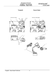
P-SERIES FILM TRANSPORT
User’s Manual
(REV. OCTOBER 2005)
2
The P3550 Platter Film Transport System
3
Thank you for selecting the BIG SKY P-SERIES Film winding system. This manual will
provide the user and installer with technical information needed to install and operate
the platter and related equipment in this system. For all other equipment (cleaners,
static, tension, etc.), please refer to the proper manuals furnished by the manufacturer.
For Information about:
Turn to page:
General Information:
Platter Specifications
Platter Outline & Dimensions
Platter Layout
4
5
6
Unpacking & Set-up
7
Operation:
General Operation, Pay-out, Take-up
Tension Sensor
Switches and Controls
Running the Show
8-9
10
11
12
Make-Up Table:
Information and procedure
Switches and Control Panel
13
14
Spare Parts List / Ordering Information
15
Equipment List
16
Warranty
17
Technical Assistance:
Troubleshooting Guide
Factory assistance & information
18
19
Drawings & Schematics
20+
4
BIG SKY P-SERIES Platter Specifications:
-3-Deck System
-Low profile design allows easier top deck access, only 49" high
-52" Aluminum decks, holds up to 25,000' of film (approx. 4 hrs)
-Simple threading pattern; no awkward reaching, looping, or pulling
-Electronic demand-only system; no switches, arms, etc.
-Mechanical Pay-out head, no electrical connections or plugs
-Each deck operates as an independent unit; no switches or moveable assemblies
-Modular design contains a minimum of spare parts
-Built-in failsafe protection from “Brain wrap”
-Audio and flashing light alarm when tension sensor activated
-Tension sensor easily connects with most automations for full system shut-down
-Built-in sensors for protection from excessive tension and pulling
-Ready to run, no adjustments needed
-Platter dimensions: 66" H x 62" L x 52" Dia. decks
-Platter weight: approx. 350 lbs.
-110/220V 50/60Hz operation
-Tested and approved to U.L. standards
5
Platter Outline and Dimensions:
6
Standard Platter Layout:
Shown below is a diagram of the P3350 Platter, indicating most major
components and controls. Further technical explanations of these components
and systems are elsewhere in this manual.
1. Platter Deck (3): 52" aluminum deck
2. Take-Up Ring (2): Ring around which film is wound during take-up
Pay-Out Head: Assembly that locates in the center of the film, controls deck speed during pay-out, and
aligns film to the rollers on the main mast
3. Speed Control Assembly (3): Part of main mast, controls individual deck speed and function
4. Deck Drive Motor (3): DC motor, located under the decks
5. Take-Up Entry Roller Assembly: Guides film from projector to proper deck control assembly
6. Pay-Out Exit Roller assembly: Guides film from tension sensor to projector
7. Pay-Out film Rollers (opposite side): guides film to tension sensor and detects film speed
8. Motor Engage Lever (3) (opp. side): Engages and disengages drive motors from decks
9. Work Lights: For bottom two decks, illuminates deck area
10. Tension Sensor: Detects fatal “Brain” wraps, and shuts down platter and console
11. Power Plate Switches and Indicators: Main On/Off Switch and Fuse, Tension Alarm light and Beeper.
12. A.C. Input Module: AC input cord location
13. Leveling Feet (4): for leveling platter on uneven surfaces.
7
Unpacking and Set-Up
Unpacking:
The BIG SKY P-Series Platter is shipped in two boxes. The mast is contained in
the rectangular box, and the three decks are packed in the square box. Unpack
the mast box, and check for the main mast assembly, horizontal crossbar, and
accessories (p-o heads, rings, etc.). Make sure all parts are present and
undamaged. Inspect the deck box for any damage before opening, then open
and inspect the contents for any damage. If there is any damage, be sure to
contact the carrier or your dealer.
Assembly:
Only two operations need to be done:
First, attach the bottom crossbar to the bottom horizontal leg, with the feet
towards the floor. Leveling the platter is recommended in case of an uneven
floor, to avoid erratic platter operation and film shift.
Second, slide each platter deck over and down each spindle until it is seated.
Make sure that the motors are in the disengaged position before lowering the
deck on the spindle.
Power-Up
The power input module is located on the bottom of the mast. Plug the line cord
into a wall outlet. The switch is located at the top of the mast and is marked “0"
for off and “I” for on. When the platter is first turned on, a short “beep” is heard as
the system initializes itself. Check that all sliders operate their motors, and that
the pay-out heads also work. The platter is now ready for use. If any adjustments
are needed, consult the control plate drawing for adjustment types and locations.
No adjustments should be needed, as each platter is factory tested and
calibrated before shipment.
8
Operation:
General Operation:
The basic operation of the BIG SKY P-SERIES Platter is similar to most other
platters available today. The entire presentation is built into one length of film on
one deck. It is wound from the beginning (inside), including previews, policies,
and advertising, to the end of the feature film (outside). The film is fed through a
pay-out head, which governs that deck’s speed, through guidance rollers, to and
through the projector, and back to the platter through guidance rollers, to a speed
control for a different deck on the same platter, and is wound around a take-up
ring on that corresponding deck. The film is ready for the next presentation by
exchanging the pay-out head and take-up ring, and re-threading the system.
P-SERIES Platters:
The same basic principle as described above is applied to the P-SERIES
Platters. The differences are in the specific designs of the decks, film path, speed
controls, function switches, etc.
The main control for each deck is it’s control plate, mounted on the side of the
main mast, correspondingly located just below the top surface of the deck it
controls. Each deck operates as it’s own independent unit, with the location of
the take-up slider determining if the deck is in take-up or pay-out mode. If the
slider is at rest (bottom of it’s travel), the pay-out head will be enabled as the
deck speed control. Once the slider is raised from the bottom position, control is
transferred to the slider itself for take-up speed control.
PAY-OUT:
In Pay-Out mode, the speed of the deck is controlled by the position of the
swinging arm in the pay-out head assembly. The pay-out head is placed in the
center of the deck, and the take-up ring is removed. Film is threaded through the
pay-out head (see the drawing for Payout Head Threading for film path) and to
the pay-out sensor rollers on the mast. These rollers sense that film is being
pulled by the projector, and the film is moving normally. As long as these rollers
are turning, operation is normal. If no movement is sensed, the control will
interrupt the speed control, and stop the deck until the rollers are being turned by
the film, which is being pulled by the projector.
9
The speed of the deck during pay-out mode is controlled by the position of the swinging
arm. As the film demand exceeds current deck speed, the arm is pulled clockwise, and
deck speed is increased to provide more film until the demand is met. If too much film is
being fed, the arm will swing in a counter-clockwise direction, and slow the deck down
until the excess film has been fed into the projector. A smooth, constant speed indicates
normal operation.
The film path through the rollers on the mast is shown in the drawings in the rear
of this manual. Different layouts are shown, depending if any cleaning or static
attachments are used, and the needed corresponding roller layout. The basic
path of the film is through the pay-out head, turning down around the sensor
rollers to the tension sensor, and up tp the exit roller assembly at the top of the
mast, and on to the projector. If a film cleaning or static device is used, it is
attached to the mast using the provided holes, and a second roller is used on
the tension sensor. This film path is accommodated with a second loop from the
first tension roller to the cleaner, back to the second tension roller, and then to
the exit roller.
TAKE-UP
After the film has traveled through the projector, sound readers, and cue sensors,
it is directed back to the platter via film guidance hardware. The film enters the
platter at the bottom of the mast through the take-up entry roller assembly.
Depending on which deck will be used for take-up, the film is then routed to the
corresponding control plate’s entry roller. The film is then routed over this roller,
down to the sliding roller, back up to the swiveling exit roller, and to and around
the take-up ring, including securing the film in the take-up ring’s catch.
The speed of the deck is controlled by the position of the slider. At rest, the slider
is at it’s bottom position, transferring control to the pay-out head. As the slider is
raised into the operating area, the motor’s speed is gradually decreased from full
to stopped, depending on how high the slider rises in it’s track. There is a six
second delay for full speed enable the first time the slider is just lifted from
rest to the full speed position. At the top of the slider’s travel is the brake
position, which will immediately stop the motor and deck until the slider lowers
back into it’s run area. On the control plate are four LED’s, listed from bottom to
top, which give the status of the deck’s operation:
Blue - Low speed or deck is stopped
Green - Cruise speed, deck is in normal speed
Yellow - High speed, deck is in high speed
Red - Brake on, indicates motor brake is applied.
Drawing No. ”Control Plate Definitions” defines all control plate functions.
10
Tension Sensor
The BIG SKY P-Series platters are all equipped with a tension sensor on the
pay-out film path. This sensor will stop the platter and sound an alarm, put the
console’s automation and projector in stop mode (if connected via the fail-safe),
and provide extra film for projector wind-down should a brain wrap occur.
The Tension Sensor is a sliding roller that is normally at rest in it’s bottom
position. Should a wrap or problem occur where the film stops feeding from the
pay-out head, the roller assembly is pulled up on it’s slider by the film tension. As
the roller rises from it’s rest position, it closes a switch which is connected to the
platter speed control, and should also be wired to the fail-safe connection on the
console’s automation. When the switch closes, the control system stops the
motor(s), and sounds an audio and visible alarm(marked “FILM TENSION
WARNING” on power panel of mast). By stopping the platter, no more film is
allowed to be fed into the developing problem. By also shutting down the
console(via the fail-safe), no system or film damage can occur since the whole
system is halted. The travel of the slider provides extra film needed for the time
period needed by the projector to stop turning.
Electrical connections and details of this sensor are depicted in the drawing,
“Film wrap Switch Wiring” in the drawing section of this manual.
11
Switches and Controls:
Main Power Switch:
Located on top panel on the Take-up side of the platter. Marked as “POWER”
The power switch is only used to turn the platter on and off.
Fuse Location and Ratings:
The fuse is located next to the power switch, and marked for rating and type.
Plug Location:
The platter uses a standard IEC type input plug assembly, and uses a standard
computer-type AC cord. It is located at the bottom of the mast on the same side.
The platters are pre-wired from the factory for either 110 or 220V operation, and noted
on the Serial Number label.
Motor Engage Control:
Each of the three motors has it’s own latch to engage or disengage the motor
drive puck against the inside lip of the deck. This latch applies pressure against
the motor, so the drive puck positively turns the deck. The handle for the latch
has two positions:
ENGAGE (towards mast)
DISENGAGE (away from mast)
pushes drive motor against platter rim
drive motor is pulled clear of platter
If the motor is not in the correct location, the platter deck will not turn. Always be
sure motors are engaged before starting any show.
12
Running The Show...
Now that the Platter is ready to use, a show can be made up and run. A typical
show consists of three parts (in order): Policy(fire, food, marquee and
organization advertising), upcoming film previews, and the feature film.
Making-up the show:
Since a platter requires the show to be one piece of film, building the print is quite
important. Typically, a make-up table is used to feed the individual segments
from a reel or roller onto a platter deck in the order of the show. Great care must
be taken to insure that all splices feature correct film orientation(front-back and
left right), and are neat and clean to ensure a correct and easy running show the
first time. Build the print in the correct order, including the correct reel # order of
the feature film. Use the supplied take-up ring, and wind the leader from the first
piece around the ring, and secure in the film catch. Continue to add policies,
previews, etc. in order, paying attention to proper orientation from film to film.
The BIG SKY Make-Up Table is part if the Film Transport System. This table
works directly with the platter to provide a simple system to make-up and breakdown films. The MUT is described on pages 12 &13 of this manual. Be sure to
follow individual theater and company instructions regarding making-up of films.
Running the show:
Once the show is built, it can be threaded and run. First, remove the take-up ring
from the center of the film by releasing the catch, compressing the ring, and
lifting straight up from the film without disturbing the wrap. Place the ring on
another deck by placing the locating pins in the correct holes. This deck is now
the take-up deck. Place the pay-out head in the center of the deck with the film,
taking care to be sure that the main body slides fully down the center opening,
and the anti-rotation pin is fully seated in it’s slot. This deck is now designated
the pay-out deck.
Thread the film through the pay-out head, rollers, tension sensor, projector, and
take-up rollers as described in the OPERATING section of this manual. Diagrams
are provided in the drawing section. The sensor roller will have to be turned by
hand to allow the deck to spin while pulling enough film out through the pay-out
head to fully thread the projector and platter. Once the film is threaded, rotate the
take-up deck CCW, allowing the motor to start and pull the excess film onto the
ring, stopping by itself when the slack is taken up. Start the console, and the
platter will automatically run as a slave to the projector’s demands and running
speed. Once the show ends, simply reverse the ring and pay-out head locations,
re-thread the system, and start again.
13
MAKE-UP TABLE:
The MUT (make-up table) is an important part of the film transport system. The MUT is
used for making-up and breaking down of any film onto/off of a platter. During make-up,
film is un-wound from a reel or core that is secured to the MUT spindle, routed through
the rollers, and wound onto a platter deck around the take-up ring. The motor on the
platter is un-plugged, and connected to, and controlled by the external motor cable from
the MUT. The typical film order is theater information and previews first, a company or
corporate promo next, and then the feature. The feature typically arrives in four to ten
smaller reels, or one to two large reels. All these individual pieces of film must be
assembled together (in the correct order and orientation) into one length of film that is
used with a platter system. Break-down is the reverse process, where this one length of
film is removed and returned to it’s original individual components. The film is pulled
from the deck back onto an empty reel or core on the MUT spindle by the internal MUT
motor. The platter motor is dis-engaged, so there is less drag on the MUT.
Film reels can have different central spindle bores, and each MUT is supplied with two
spindle assemblies, 5/16" and ½". Spindle assemblies are changed by pulling the spring
loaded release pin, and removing the spindle assembly by pulling it forwards out of the
coupling. Insert the desired spindle assembly into the coupling, and release the pin,
being sure that it is properly snapped into the detent in the spindle assembly. If needed,
the drive “dogs” can be repositioned on each spindle assembly to properly catch the
reel drive holes. The film reel is slid onto the spindle shaft via it’s central bore, being
sure to align the drive dog through one of the drive holes in the film reel hub. The film
reel MUST be secured to the spindle assembly with the safety clip, so that the reel
cannot slide off the spindle during winding. Failing to do so will result in film and
equipment damage. The exit roller assembly is moved vertically up and down the
vertical post by loosening the arm clamp. Position the exit roller assembly so that the
film path is parallel to the platter deck being used, and winds the film flat and even on
the deck. Refer to DWG.# PMUT FILM PATH for the proper threading path of the MUT.
Proper operating procedure includes smooth and gradual film speed changes to avoid
any sudden jerking or spillage of film.
14
Power and Switch location:
The main power switch is on the bottom panel of the main enclosure, towards the right
front corner. The fuse holder is behind the switch, and the receptacle for the power cord
is farthest rearward. Fuse replacement is as marked by the fuse label, using a 5 amp,
slow-blow fuse only.
MAKE-UP TABLE CONTROL PANEL:
All table functions are controlled from the control panel. Power is indicated by the “RUN
and STOP” LED’s. The MAKE-UP / BREAK-DOWN Switch controls spindle direction.
In Make-up mode (YELLOW LED), power is diverted to the Platter deck motor via the
connecting cable. Speed is controlled by rotating the speed knob, increasing speed as
the knob is rotated clockwise. During Break-Down (GREEN LED), the internal table
motor runs, pulling the film off the platter, and onto a reel mounted on the spindle. The
platter motor is dis-engaged, allowing the deck to spin freely. Speed is controlled by the
speed knob. If, during the film transfer operation, the reel or deck needs to be stopped
or slowed down, depressing the “STOP” switch will slow and stop the controlled
function. Remember that both motors will be slowed during make-up, but only the table
motor will be slowed during break-down, as the platter motor is dis-engaged, and the
deck is spinning free. The “RUN” light “green” is on when the table is operating
normally, and the stop “RED” light is on when the brake is applied. After the brake is
used, the control must be reset by rotating the speed control fully counter-clockwise,
and then pressing the RUN button to go back into RUN mode. Proceed again with the
film winding process.
15
Parts List:
The following is a listing of frequently ordered spare parts available for the P-SERIES
Platter and MUT. They may be ordered through your dealer. For parts not listed or for
more information, please contact your dealer or BIG SKY directly.
PPLATE
PHEAD
PLROLLER
PSROLLER
PTPLATE
Control Plate Assembly (exchange only)
Pay Out Head Assy.
Large 2-Pc. Roller
Sense Roller Assy.
Transformer Plate Assy.
PMUTMTR
PMUTSP-5/16
PMUTSP-1/2
PMUTDB
PMUTCP
PMUTLTRA
PMUTESRA
PMUTESBA
Make-Up Table (MUT) Motor
MUT 5/16" Spindle Assy
MUT ½” Spindle Assy
MUT Drive Belt
MUT Control Panel Assy
MUT Lower Turn-around Roller Assy.
MUT Exit Swivel Roller Assy.
MUT Exit Slide Bracket Assy
16
Equipment List:
The P-SERIES Platter is one of a series of motion picture projection, lighting and
accessory equipment available from BIG SKY Industries. A complete line of automations,
lighting controls, consoles, projectors, sound equipment, platter systems,
lamphouses, power supplies an ignitors, film guidance hardware and accessories are
available. For product specifications, pricing and ordering information, contact your
dealer.
Consoles:
C2000 2K console
C3000 3K console
C4000 4K console
C7000 5-7K console
Sound Equipment:
S1000 Sound Rack; 40 rack
S1200 Sound Rack; 40 rack, blower, contactor, receptacles
S1400 Sound Rack; X1200 plus prewire for custom comp.
S2000 Monitor Panel
Deluxe consoles:
C2000D 2k extended console
C3000D 3k extended console
Film guidance Hardware:
FH1000 Arms w/platter guidance hardware
FH1100 Wall-mount guidance hardware
FH1200 Wall-mount fixed roller
FH1300 Swing-arm accumulator
FH1400 Roller on bar
Console options:
Rotron blower w/air vane switch
Additional breakers
Prewire sound in deluxe consoles
Prewire projector
Time-delay circuit for blowers
Main contactor
Automations:
A2000 Matrix automation
A2108 8-screen remote
A2116 16-screen remote
A2124 24-screen remote
Automation options/accessories:
Clock timer
Optical failsafe w/micro-switch failsafe
Sensing tape, optical
Lighting controls:
D4000 Single-channel 4K Dimmer
D4400 Dual-channel 4K Dimmer
Projectors:
E15M Ernemann 15 Projector/Manual
E15A Ernemann 15 Projector/auto.
ESRD Dolby Digital Reader
E15 Ernemann 15 Complete System
Replacement Parts:
C1050 10.5" Dichroic Reflector
C1060 13.5" Dichroic Reflector
C1070 12" Glass Dichroic Reflector
Platter Systems:
P3350 3-Deck Platter System
P3700 3-Deck Platter System
P5350 5-Deck Platter System
PMT35 35mm Make-up Table
PMT70 35/70 mm Make-Up Table
Platter Accessories:
P1350 35mm Payout Head
P1700 70mm Payout Head
P1351 35mm Take-Up Ring
P171 70mm Take-Up Ring
Lamphouses:
L2000 1-2000w Lamphouse
L3000 2-3000w Lamphouse
L4000 3-4000w Lamphouse
L7000 5-7000w Lamphouse
Power Supplies & ignitors:
N3X75 IREM 2000 watt power supply
N3X7595 IREM 3000 watt power supply
N3X95159 IREM 4000 watt power supply
N3X180 IREM 7000 watt power supply
N3X10K IREM 10,000 watt power supply
AFU200 Auxiliary Filter Unit
AS16D40M IREM Ignitor
ASN700A IREM Ignitor, low-noise
17
Warranty:
All BIG SKY products and accessories are warranted against malfunction or failure due
to defects in workmanship or materials for a period of one year from the date of
shipment. If a problem occurs during the warranty period, the unit will be repaired or
replaced (at BIG SKY’s option) without charge for materials or labor. This limited
warranty does not cover products that have been altered, abused, modified, or
operated in other than specified conditions.
Our limited warranty does not cover damages resulting from accident, misuse or abuse,
lack of responsible care, or failures not attributable to manufacturing defects. BIG SKY
INDUSTRIES Inc. makes no warranties, express or implied, including warranties of
merchantability or fitness for a particular purpose. Final warranty decisions are to be
made by BIG SKY INDUSTRIES only.
RETURN POLICY: Factory authorization MUST be obtained before returning any
product. A 15% restocking charge will be issued on unused equipment (in original box)
that is returned for credit. Credit is issued to the dealer’s account only.
WARRANTY SHIPPING: All returns must be shipped freight pre-paid by the dealer.
Equipment returned without a factory return authorization (RA) will be refused. RA
number must be written clearly on the shipping box. If air freight is requested by the
dealer, the difference between air and ground will be billed to the dealer.
18
Troubleshooting guide:
If the platter should not operate properly, first check the following guide to determine
the cause. If, after checking the guide, operation is still not proper, contact your dealer
or an authorized theatre equipment service person.
Problem:
Solution:
Platter does not Power-up
Power switch “off”
Platter fuse open
Breaker in console off
Breaker in wall box off
AC line cord plug not properly connected
Platter does not operate in Pay-Out Pay-out head not fully inserted
Take-up slider not fully seated
Sensor rollers not turning
Motor not engaged or plugged in
Loose, damaged, or missing motor drive puck
Pay-out head out of adjustment
Gradient damaged or missing on target puck
Loose, damaged, or missing internal wiring
Tension sensor not at bottom position
Magnet on Payout sprocket roller is missing.
Platter does not operate in Take-up
Slider not in operating range
Motor not engaged or plugged in
Loose, damaged, or missing motor drive puck
Tension sensor not at bottom position
Loose, damaged, or missing internal wiring
Check for film wrap or jam
Make-Up Table does not Power-up
Power switch off
Main fuse open
Plug not fully seated in power input module
No power at outlet being used
Problem with main board in MUT
Make-Up Table operates incorrectly
Film threaded incorrectly
Exit roller assembly not clamped or correctly aligned with platter deck
Speed control not reset after using the brake
MUT in wrong mode (Make-up vs, Break down)
Wrong spindle assembly (shaft dia) or drive “dog” position
Spindle assembly not fully seated in locking collar
19
Factory assistance & information:
If you have checked the troubleshooting guide and are still having
problems with operation, contact your theater equipment dealer. If you are
unable to resolve your problem quickly or easily, contact BIG SKY Industries’
Engineering department at:
BIG SKY INDUSTRIES
1475 Park Ave.
Alpha, NJ 08865
908-454-6344
908-454-6373(fax)
Monday to Friday, 8:30AM to 5:00PM E.S.T.
You may also obtain additional product information by calling this number.
Corporate website: www.bigskyindustries.net


![Rii Mini [Bluetooth]](http://vs1.manualzilla.com/store/data/005730343_1-53cd9486bcc3b780c33a2a4f5175af21-150x150.png)