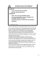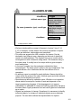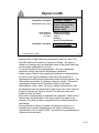
1
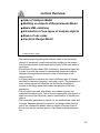
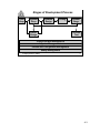
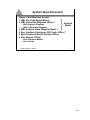
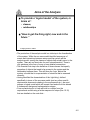
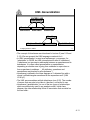
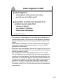
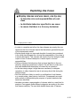
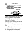
D50: Advances in Software Engineering
Analysis Model
Wolfgang Emmerich
© Wolfgang Emmerich, 1998/99
1
• Last week, we have started to look at Ivar Jacobson's object-oriented
software engineering method. We have seen how use cases model
the different ways that actors interact with a system.
• We have also seen examples of type/instance relationships. One use
case models different similar interactions between actors and the
system. We referred to as instances of use cases as scenarios.
Moreover we have separated actors and users. Again an actor
identifies the type for multiple similar users.
• The purpose of this lecture is to discuss the Analysis Model. More
precisely we are going to discuss the question: What constitutes the
Analysis Model and how is the result of the Requirements Model
transformed into the Analysis model?
4-1
Lecture Overview
Aims of Analysis Model
■ Building on outputs of Requirements Model
■ Basic UML notations
■ Introduction of new types of analysis objects
■ Reuse of use cases
■ Inputs for Design Model
■
© Wolfgang Emmerich, 1998/99
2
• The lecture begins by placing the analysis model in the theoretical
context of Jacobson’s overall view and then building on the outputs
from the requirements model stage as the inputs for the next steps in
production.
• We will then introduce basic UML notations for classes and object etc.
in order to provide the means for representing classes and objects
defined in the requirements model in order to refine them in the
analysis model.
• It is then possible to introduce the roles of different types of classes
identified by Jacobson (interface, entity and control). The separation of
these roles supports and simplifies the successive modelling of
classes in the design phase and makes the analysis model more
expressive.
• The use cases are used, and refined, as a means to guide, and
evaluate the analysis work. This is done by tracking the descriptions of
each use case to the influence it had on specifications of classes and
objects.
• The cumulative generation of outputs (i.e. the enriched use cases and
the class diagrams) provide the inputs for the design model, the first
part of the ‘construction phase’ which is subject of lectures 5 and 6.
• Let us now use the overview picture of last week to review where we
are...
4-2
Stages of Development Process
User
Reqs
System
Reqs
Detailed
Design
Coding
Archit.
Design
System
Integr.
Pre-Prod.
Test
Project and Risk Management
System Management
Version and Configuration Management
Quality Management
© Wolfgang Emmerich, 1998/99
3
4-3
System Reqs Document
Owner: Chief Business Analyst
1 UML Use Case Model (Rose) +
2 UML Interaction Diagrams (Rose) +
• UML Sequence Diagrams
• UML Collaboration Diagrams
3
4
5
6
Analysis
Model
UML Analysis Class Diagram (Rose) +
User Interface Prototypes (GUI Tools, Office) *
Specification of Report Format (Office)
User Manual (Office)
• User Reference Manual
• User’s Guide
© Wolfgang Emmerich, 1998/99
4
4-4
Aims of the Analysis
■
To provide a ‘logical model’ of the system, in
terms of :
• classes,
• relationships
■
“How to get the thing right, now and in the
future “
© Wolfgang Emmerich, 1998/99
5
• The production of the analysis model is a vital step in the formalisation
of the system. While the use case model identified sequences of
events and interactions between actors and the system will the
analysis model specify the classes of objects that actually occur in the
system. There are no fixed rules for such a transformation. There is
only guidance in the form of more or less detailed conventions.
• The essential first step is the definition of those classes that specify
properties of objects that need to be present in the system and the
relationship between them. This will show the ‘logic’ behind the
system, a model that is a reprsentation of structure that is reasoned
correctly.
• Having identified the characteristics of the ‘right thing’, defined
specifically in terms of the use case model (and any other specific
requirements documents relating to the environment etc.), we must
prepare a logical model which will remain fixed and will not be altered
in subsequent design and implementation stages.
• From a practical point of view will build on outputs from the
requirements model using a further sequence of steps (Nos 10-15)
that are detailed on the next slide...
4-5
Producing an Analysis Model
■
■
Inputs
Actions
10
11
12
13
14
15
■
■
Draft initial class diagram
Re-examine use case and object behaviour
Refine class diagram
Execute check
Revise class diagram
Group classes into packages
Outputs
Notations
© Wolfgang Emmerich, 1998/99
6
• The production of the analysis model begins with the elaboration of
the problem domain objects into the initial class diagram. In this step,
we will take commonalities between similar domain objects into
account and model them as classes. We will also try to identify
commonalities between different classes and identify these as
generalisation and specialisation relationships.
• The first step develops a draft class diagram. It is followed by a reexamination of use cases in order to prepare for modelling the
necessary behaviour of objects in a way that they reflect the use
cases.
• We then refine the class diagram so that it reflects the behaviour of
the use cases. In order to do this we map actions mentioned in the
use case into operations of some classes and model use case state
information as attributes of classes.
• We then validate that every information provided in the use cases has
been considered in the class diagram.
• If necessary we revise the class diagram in order to avoid loosing
information from the use case diagrams.
• The grouping of classes into packages is not only an analysis
modelling activity, it is also an essential managerial step to keep the
development process manageable. The suggestion to perform the
packaging step at the end will only work for very small scale projects.
Depending on the scale of the project it might be necessary to develop
the class diagram in a packaged form and revisit the packaging
whenever the class diagram is to be revised.
• Let us now consider the inputs and outputs of the analysis phase on
the next slide...
4-6
Analysis Input and Outputs
■
Inputs:
• uses cases and use case model
• problem domain object list
■
Outputs:
• class roles and responsibilities [text]
• use case description in terms of classes and
operations [text x use case]
• completed analysis model [class and package
diagrams]
© Wolfgang Emmerich, 1998/99
7
• The most important input of the analysis phase are the use cases and
the use case model produced in the requirements phase. Also we take
the list of problem domain objects produced at the end of the analysis
phase as a starting point for the definition of the class diagram.
• The most relevant output of this phase is the class diagram that
reflects the attributes, operations and relationships between the
classes that represent the objects occurring in the use case. The class
diagram will be structured into different packages that contain classes
with a high internal coupling.
• In addition, the check that the behaviour of textual use case
descriptions has been properly reflected in the class diagram will
produce use case diagrams in terms of classes and their relationships.
On the other side it will identify for each class the different roles that
the class will play with respect to the use cases. In that way bidirectional traceability is provided that will simplify completeness and
change impact analysis.
• The first step of the transfer from the requirements model to a logical
analysis model is the production of an initial class diagram. This
requires the use of standard UML notation, the first being the class
that is detailed on the next slide...
4-7
Notations
Class (rectangle containing name, attributes,
operations)
■ Object (rectangle plus obx:Cx)
■ Association (by value/aggregation,
cardinality/multiplicity)
■ Generalisation (UML term replacing OOSE
‘inheritance’)
■ Package
■ Depends association
■
© Wolfgang Emmerich, 1998/99
8
4-8
CLASSES IN UML
className
attribute name: type
Op name (parameter: type): result type
className
© Wolfgang Emmerich, 1998/99
Polygon
centre: Point
vertices: List of Point
borderColour: Colour
fillColour: Colour
display (on: Surface)
rotate (angle: Integer)
erase ()
destroy ()
select (p: point): Boolean
Polygon
9
• We have introduced the concept of classes in Lecture 2 (see 2.14,
2.15). In essence, a class defines the common properties of objects.
These are attributes, relationships and operations.
• This slide now presents the UML notations for classes. Can be
declared in two different ways, depending on the level of detail that
needs to be defined/shown. The simplest form is just a solid-outline
rectangular box with a character string inside. The character string is
the class name. It usually has to be unique within a given scope to
avoid ambiguities.
• In the more complex form the rectangle is divided into three
compartments. The class name is given in the top compartment. The
second defines a list of attributes and the third defines a list of
operations.
• An attribute name is provided for each attributes. Names should be
unique within the scope of the class. Attribute types and initial attribute
values can be defined as an option.
• Operations are defined by operation name. Whether or not operation
names should be unique is a matter of taste and depends on the
target programming language. If the languages do not support
overloading it is advisable to refrain from defining operations that have
the same name. Again parameter lists and result types can be defined
as an option.
• Objects are instances of classes. Sometimes it is necessary to identify
individual objects, for instance if individual objects serve a particular
purpose. The next slide outlines the representation for objects...
4-9
Objects in UML
objectName: className
attribute name: type = value
(same operations
for all instances
of a class)
objectName: className
© Wolfgang Emmerich, 1998/99
triangle1: Polygon
centre = (0,0)
vertices = (0,0), (4,0), (4,3)
borderColour: black
fillColour: white
display (on: Surface)
rotate (angle: Integer)
erase ()
destroy ()
select (p: point): Boolean
triangle1: Polygon
10
• Again the idea of object has been discussed in Lecture 2 (see 2.16)
• The UML defines the notation for objects as follows: “An object is
drawn as a rectangle with an underlined name of the object name and
its class name (separated by a colon).”
• “It may be divided into two compartments. The top compartment
contains a string in the format: objectName: classname."
• Unlike classes, objects have a particular state that is characterised by
the value of the object's attributes. Note that in the presence of
inheritance the object inherits attributes from all its super classes. The
UML defines the notation for attribute values as follows: "The bottom
compartment contains a list of attribute values in the format:
attributeName: type = value. The type is usually omitted since it can
be determined from the class itself as well as the form of the value but
it may be included for claruty if needed. The attribute name must
match one from the class."
• Note that it is unnecessary to determine the operations. These can be
inferred from the declaration of the class of which the object is an
instance. The object would be overspecified if we defined operations
redundantly.
• Having identified a variety of classes, the analysis must go on to
consider their common characteristics, the issue of inheritance or
‘generalisation’ as it is called in UML. The notation for generalisation is
outlined on the next slide...
4-10
UML Generalization
SUPERCLASS
Staff Member
Librarian
Lecturer
Researcher
SUBCLASS
SUBCLASS
SUBCLASS
Handler
KeyboardHandler
© Wolfgang Emmerich, 1998/99
MouseHandler
JoystickHandler
11
• The concept of inheritance was introduced in Lecture 2 (see 2.18 and
2.19). We now present the UML language constructs for it.
• In UML ‘generalisation’ is used as a replacement, or synonym, for
‘inheritance’ in OOSE, but UML documents still refer to ‘inheritance’
(“Inheritance is a taxonomic relationship between a superclass and its
subclasses. It is often called generalisation or specialisation
depending on whether one is going from subclass to super class or
from superclass to subclass. ... All attributes, operations and
associations are inherited by all subclasses.”)
• Inheritance is defined in the class diagram as “a directed line with a
closed, unfilled triangular arrowhead at the superclass end” (UML
V0.91 p7).
• The UML accommodates multiple inheritance (see 2.20). The number
of arrows that may start at a class is, therefore, not limited to one.
• Inheritance (‘generalisation’) is one of the two types of relationships
which are extensively used in any analysis model / initial class
diagram; the other relationship is that of association that we detail on
the next slide...
4-11
Associations in UML
bidirectional / binary
unidirectional
“by value” / aggregation
“by reference”
association name
[+ single directional arrow]
role name
multiplicity
© Wolfgang Emmerich, 1998/99
role name
multiplicity
supplementary
characteristics
12
• Associations represent structural relationships between objects of
different classes, representing information that must be preserved for
some duration.
• Bidirectional associations are traversable in both directions. It is the
least explicit association and most common at early stages of
analysis. Bidirectional associations are usually refined during the
course of the analysis by giving it an aggregation or reference
semantics, identifying different multiplicities and by making the roles
explicit that the connected classes play in the association.
• Unidirectional associations imply that the implementation should make
it straightforward to navigate from a source object to a target object
across the association. Unidirectional associations are regularly
implemented by pointer type instance variables.
• Aggregation implies that instances of one class are embedded within
instances of another class. The instances therefore form composite
objects; ‘by reference’ relationships are used to refer to other objects.
• An association may have a name with an optional small “direction
arrow” showing which way it is read, e.g. employer employs >
employee.
• As an attribute of a role, multiplicity shows how many instances of the
attached class may be associated with a single instance of the object
at the other end of the association. '*' is used for “none to many”.
• Associations are an extremely powerful concept that can be
elaborated and used in many ways as the following examples
suggest...
4-12
Association Examples in UML
authorised on >
User
*
*
Workstation
AttributesOfClass
Authorisation
priorities
privileges
1
ClassDecl
1
OperationOfClass
start session()
* home directory
1
Directory
© Wolfgang Emmerich, 1998/99
*
Attribute
*
Operation
13
• In the relational data model relationships can have attributes in order
to characterise properties of relationships. For the same reason,
associations in the UML can have specific properties by attaching a
class to them. The object-oriented approach is even more powerful
than the relational approach because properties of associations may
not only be attributes, but also operations and other relationships. The
‘association class’ is represented by a class rectangle attached by a
dashed line to the main link, as shown in left-hand example.
• In the example, the 'authorised_on' relationship has attributes that
identify the priorities and privileges that go with the authorisation and
an operation that is used to check the authorisation during the startup
of a session. The 'association class' also has an association that
identifies the home directory for each potential authorisation record.
Assuming that the user has the same home directory on every
workstation the multiplicity of this association is many to one.
• The right hand diagram shows a very small segment of the UML ‘meta
model’. The purpose of the meta model is to the notation itself to
identify how the notation is structured. This example represents the
class of objects containing all class object declarations.
• Now that we know all the ingredients we can start modelling a class
diagram ...
4-13
Class Diagrams in UML
■
Class diagrams :
• show logical, static structure of system
• provide core of ‘unified model’
■
Generation of initial class diagram from
problem domain object list
• classes of objects
• associations / attributes
• inheritance relationships
© Wolfgang Emmerich, 1998/99
14
• The purpose of a class diagram is to provide a generic description of
possible system states. This is done in a class diagram by modelling
classes that describe the common static properties of similar domain
objects.
• At this stage of modelling we are only concerned with identifying the
attributes of classes and to analyse similarities in order to identify
generalisation relationships.
• Please note that class diagrams describe the system from a type level
perspective. They are, therefore, not concerned with particular objects
that are instances of classes.
• Class diagram provides a single, albeit essential, view of a system.
The class diagram is the core of the UML and other views organised
according to the class diagram. The other views are provided by: use
case model (3.13) sequence diagram showing interaction between set
of objects (part of design model) and state diagram showing temporal
evolution of an object of a given class (also part of design model).
• We are now in a position to attempt the first stage in the production of
the analysis model (10 on 4.5) using the output from the requirements
model as input...
4-14
A ‘Recycling Machine’ Class Diagram
Deposit Item
Receipt
Name
Deposit value
Daily total
Total cans
Total bottles
Total crates
Can
Bottle
Crate
Width
Height
Neck
Length
Bottom
Width
Height
Length
© Wolfgang Emmerich, 1998/99
Customer panel
Operator panel
15
• This slide depicts the initial class diagram that we have derived from
the use case descriptions of the recycling machine example. This is
how we got there:
• We have started from the list of domain objects produced as part of
the requirements model and have drawn a class representation for
each of the items.
• After that, we have assigned different domain attributes in order to
model states of real world objects.
• When we had identified the attributes of classes, we recognised that
cans, bottles and crates have several attributes in common. In order to
avoid this duplication we have done a generalisation and created the
class 'Deposit Item', declared these attributes for Deposit Item and
then introduced the generalisation relationship.
• Note that it need not be done this way around. We could also have
spotted an abstract class for deposit item, declared the attributes and
then introduced the generalisation relationship.
• As a first plausibility check we can see whether every attribute defined
in a generalised class makes sense in every single subclass.
• Note that the class diagram produced now is far from being complete.
Operation specifications are missing. Also the class diagram
represents one of any number of alternatives, e.g. to define a class of
objects which contain dimensional measurements for any recycleable
item, or alter ‘Deposit Item’ to include these.
• The question that arises now is how do we proceed to improve such a
draft diagram? The clue is that we have essential output from the
requirements model stage, the use cases...
4-15
Exploiting Use Cases
■
Employ classes and use cases, one by one,
• to describe roles and responsibilities of each
class
• to distribute behaviour specified in use cases
• to ensure that there is a for every behaviour
© Wolfgang Emmerich, 1998/99
16
• In order to complete and refine the class diagram we employ the use
cases and the list of domain objects that have been generated as part
of the requirements model.
• We take each single use case and describe for each class contained
in the initial class diagram the role and the responsibility of the class in
a textual description. This exercise will result in the first analysis model
output in form of textual description of each object’s role and
responsibilities.
• We then distribute the behaviour that we have identified in the use
cases by assigning operations to objects. We will have to make sure
that each behavioural description is covered by an operation.
• At the later design stage it might become necessary to delegate
operations to other classes but we do not worry about this during the
analysis stage.
• Also this exercise is likely to result in a proliferation of odd classes,
e.g. receipt printer, alarm device, bottle slot. Consequently we need
some means of differentiating the purpose of system elements that
have been identified.
• Jacobson provides a categorisation of classes which is a useful aid to
analysis. He suggests three different categories according to the roles
that classes can play. The next slide details these roles of classes...
4-16
Roles of Classes in OOSE
Interface classes - for everything concerned
with system interfaces
■ Entity classes - for persistent information and
behaviour coupled to it
■ Control classes - for functionality not
normally tied to other classes
■
<< interface >>
interface name
■
<< entity >>
entity name
<< control >>
control name
Integrated into UML as stereotypes:
© Wolfgang Emmerich, 1998/99
17
• Actors use the system's interface to interact with a system. The actors
can be people using the system or other systems for the exchange of
information. People would need to interact through a user interface
with the system and likewise other systems need an interface.
Jacobson suggests to denote classes defining the operations that are
available at a user or a system interface as interface classes.
• Other classes store information and object states in attributes. These
classes would be considered as entity classes according to
Jacobson's taxonomy.
• Control objects are the most ‘fuzzy’ category. They are required to
contain operations coordinating the interaction with other objects, the
computation and result delivery e.g. to calculate value of recycled
items. Typically a control object contains functionality unique to one or
a few use cases.
• Stereotypes provide meta classifications of elements in UML and an
iconised representation for them. Stereotypes add information about a
class that is exploited in the design stage. Interface classes, for
instance, need to be designed in a way that their instances can be
accessed from distributed objects (these are objects running on other
machines). A particular stereotype is named at the top of the box
between double arrows. In its simplest form (as used by Jacobson) the
icon and the class name are sufficient.
• Note, that this is a ‘shorthand version’ for a complete definition of a
class, but not a permanent substitute.
• Now we consider these roles of classes in greater detail...
4-17
Interface Classes
Contain functionality directly dependant on
system environment
■ Definitions focus on interaction between
actors and use cases
■
Receipt Receiver
Receipt
Printer
Customer Customer
Panel
© Wolfgang Emmerich, 1998/99
Operator
Panel
Alarm
Device
Operator
18
• An important concern in the integration of complex system is to make
sure that the systems remain well separated. It is therefore
undesirable to have one system accessing the operations of another
system directly. This would violate the important principle of
information hiding. The systems should rather be interconnected
through connectors which can isolate the systems from each other.
Interface classes do fufill this purpose.
• Interface classes provide also a chance to the system analyst to make
clear system boundary and declare all the interfaces provided across
it. As part of the interface specification, interactions that the system
can have with its actors are specified. Recall that actors can be human
users as well as other systems.
• The interactions we are concerned with at the system interface level
include
• issuing a request to an actor,
• providing information for an actor,
• receiving a request from an actor, and
• obtaining information from an actor.
• It is possible to represent each interface class as a ‘plain’ UML class
box. However, an explicit diagram like this where classes are
represented using there stereotypical representations emphasises the
essential dependency relationships across the system boundary, an
important information to have during a later design.
4-18
Associations between Interface Classes
Definition of both dynamic
■ and static associations
■
<< interface >>
Receipt button
<< interface >>
Receipt
Printer
Operator
Panel
<< interface >>
Customer Panel
Crate slot
<< interface >>
Can slot
Customer
Panel
<< interface >>
Alarm
Device
© Wolfgang Emmerich, 1998/99
Bottle slot
19
• In order to enable interface objects to send a message to another
interface object the interface objects need to be associated with each
other and we use UML associations for that purpose.
• In OOSE the simplest form of binary association is static and given the
name ‘acquaintance’. This would be appropriate to describe, in most
general way, the relationships in the left hand diagram. However, we
can already be more explicit and identify these associations as being
both dynamic and unidirectional, so have used the arrowed line
notation introduced earlier (confer page 4-10).
• The right-hand side displays an aggregation association between
interface classes. This again is a regular pattern as complex user
interfaces tend to be composed of simpler objects. In the example the
aggregation corresponds to the composition of the user interface of
the recycling machine.
• We could have even add further information to all these associations
eg names on left and multiplicity on right.
• Interface objects are not designed to contain information; this is the
principle role of the entity object as we will see on the next slide...
4-19
Attributes of Entity Classes
■
Purposes of entity
classes :
• To store information
persisting after
completion of a use case
• To define behaviour for
manipulating this
information
<< entity >>
Deposit Item
Name: String
Deposit value: ECU
Daily total: Integer
<< entity >> << entity >> << entity >>
Can
Bottle
Crate
© Wolfgang Emmerich, 1998/99
20
• The classes modelling the domain objects that were part of the list
produced at the end of the requirements stage will be classified as
entity classes.
• Entity classes typically have attributes that are capable of storing
information. As class diagrams are at type level, we are not concerned
about actual attribute values. Only objects that have been instantiated
from the class have different attribute values.
• This diagram shows the next stage of elaboration of classes to include
attribute types. The typing of attributes restricts the domain that the
value of these attributes can have in objects instantiated from the
class.
• The domain might even further be restricted but this restriction is
usually implemented by operations.
• A negative daily total value would not make sense for instantiations of
any deposit item. This, so called, integrity constraint is then
implemented by operations that would not allow the assignment of
negative values to the attribute.
• Hence the next step to consider is the behavioural specification for
classes (the third compartment). This is dictated by operations and
messages that are sent between objects in order to invoke the
operations.
4-20
Entity Communication
■
A primary task to identify associations
involving communication
• modelling of communication between objects
• shows the sending and receiving of messages as
stimuli
• starts from object initiating communication
• directed to object where reply generated or
operation executed
Receipt Basis
© Wolfgang Emmerich, 1998/99
Deposit Item
21
• In order to be able to send a message to an object the requesting
object has to know the identity of the object. One way to obtain the
identity is to traverse along an association.
• These assocaitions need to be defined in the class diagram.
Associations that are used purely for message passing purposes tend
to be directed because they need to be traversed from the sender in
order to identify the receiver.
• The diagram shows such a <<communication >> association between
a class for recording a customer's returns and class recording daily
totals.
• The definition of associations provides the basis for completing the
definition of operations as discussed on the next slide...
4-21
Entity Operations
■
Defining entity operations for:
• storing and fetching information
• creating and removing object
• behaviour that must change if
entity object is changed
<< entity >>
Deposit Item
Name: String
Deposit value: ECU
Daily total: Integer
Create ()
setValue (integer)
Increment ()
© Wolfgang Emmerich, 1998/99
22
• Operations provided by entity classes are defined for the above
purposes.
• Operations that store information typically check integrity constraints
of the object (e.g. to make sure that the daily total value does not
become negative and that positive values are added only). Operations
defining the fetching of information typically check access rights of the
principal requesting the information before providing it.
• Special operations define the creation and removal of objects. An
operation that creates a new object by instantiating a class is referred
to as a constructor while the operation that removes an existing object
is referred to as a destructor. Constructors typically perform attribute
initialisations and destructors release storage space occupied by the
object.
• Other operations may be provided in order to implement different state
transitions that objects of the specified class might be involved in.
• In general operations are used in order to hide object states that
should not be exposed to other objects. This contributes to the
principle of information hiding (though on a finer level of granularity
than interface classes) (for a discussion of information hiding refer to
slides 2-12 and 2-13)
• Note that Jacobson's OOSE method does not consider it to be
essential to define specific operations at the analysis stage.
• Now we discuss the third role that classes can play, which is the least
clear defined...
4-22
Control Classes
■
Control classes needed to
provide for:
• behaviour not natural in
interface and entity classes
• ’glue’ between other classes
in use case
report
generator
• typical control behaviours
• improved maintainability information
administrator
© Wolfgang Emmerich, 1998/99
deposit item
receiver
extends
alarm
device
23
• Even in object-oriented decompositions of systems, there is
sometimes a need for accomodating functions in order to model
behaviour that does not directly relate to properties of objects. This
behaviour is modelled as operations of classes that are control
classes.
• Control classes provide the glue between interface classes and entity
classes. To construct stable systems in the real world, one should not
use too much glue but only use it to fill the gaps between components.
This is the same with object-oriented modelling. Control classes
should be deployed with care.
• Control classes should be used to represent use cases involve some
form of coordination operation, such as
•transaction-related behaviour,
•specific control sequences, and
•functions separating interface and entity objects
• The algorithms performed by these coordination operations are
subject to frequent change. That makes it necessary to isolate them in
separate objects to be maintained separately.
• In a preliminary draft assign one control object to each use case.
Where the situation is more complex, aim for one per actor. The
emphasis, as before, is on usefulness of use cases.
• With all these objects we can build up ‘use case views’ and packages
as shown on the next slide...
4-23
Use Case View
Model each use case
■ Describe use case in terms of classes
■
Customer
Panel
Deposit Item
Receiver
1
0 .. n
Receipt
Basis
Deposit Item
Can
© Wolfgang Emmerich, 1998/99
Receipt
printer
Bottle
Crate
24
• The next step in the analysis is to take each use case and model it in
terms of a class diagram fragment. This is a significant step towards
the formalisation of use cases and a test whether all the classes are
provided that are needed for the use cases.
• Note that the same class might occur in many different fragments in
the same way as the same actors and real world entities occur in
different use cases.
• The diagram on this slide shows part model only of objects supporting
use case ‘Returning item’.
• As a next check we will convince ourselves and any stakeholders that
what we have modelled in terms of classes really reflects the real
world. This is examplified on the next slide...
4-24
An elaborated Use Case
When the customer returns a deposit item the Customer
Panel’s sensors measure its dimensions. These
measurements are sent to the control object Deposit Item
Receiver which checks via Deposit Item whether it is
acceptable. If so, Receipt Basis increments the customer
total and the daily total is also incremented. If it is not
accepted, Deposit Item Receiver signals this back to
Customer Panel which signals NOT VALID.
When the Customer presses the receipt button, Customer
Panel detects this and sends this message to Deposit Item
Receiver. Deposit Item Receiver first prints the date via
Receipt Printer and then asks Receipt Basis to go through
the customer’s returned items and sum them. This
information is sent back to Deposit Item Receiver which
asks Receipt Printer to print it out.
© Wolfgang Emmerich, 1998/99
25
• This slide displays the rewriting of the use case we had on the slide
before in terms of classes. This is referred to as an elaborated use
case.
• This elaborated use case serves three purposes:
• While performing the exercise of rewriting the use case we
double check that every information we had in the previous
description is covered in the class diagram.
• We establish direct links between the use case and the class
diagram. This allows tracking user requirements reflected by
use cases through the analysis into the design. This traceability
is an important basis for analysing the impact of changes to the
requirements.
• Stakeholders would not necessarily be able to understand class
diagrams, though they can understand this textual description.
Through validating these elaborated use cases they indirectly
check the class diagram.
• The amalgamation of individual parts provided by ‘use case
views’ into one whole requires some kind of modularisation. In
UML there are now generic ‘packages’, which subsume OOSE
subsystems. We introduce packages on the next slide...
4-25
Packages
Packages are a way to decompose class
diagrams into manageable units
■ Packages are necessary:
■
• because of large numbers of classes
• to provide optional functionality
• to minimise effect of change
© Wolfgang Emmerich, 1998/99
26
• In real-life projects a sheer amount of classes needs to be handled.
Even small scale projects easily have 100 classes and (remember the
7 +/- 2 rule) these cannot be overlooked by humans any more and
therefore have to be structured.
• Packages are the language concept offered by the UML for grouping
classes. Packages are displayed as a tabbed folder.
4-26
Packages (Cont’d)
■
Packages should have a:
• tight functional coupling inside
• weak coupling outside indicated by ’dependency
associations’ between packages
■
Packages may:
• ‘contain’ nested packages with ‘service packages’
as atomic parts
• have individual classes outside
• be result of organisational or managerial
pressures
© Wolfgang Emmerich, 1998/99
27
• A package may contain classes and/or nested packages. Classes
should be arranged into packages so that there is a tight coupling
within the package but a weak coupling in between different
packages. Note that the generalisation relationship provides a very
very strong coupling and it is therefore useful to arrange for classes
that inherit from each other to be in the same package.
• As classes from within one package may need to be associated with
classes contained in other packages, the need arises to interface
between packages. We therefore use a dependency association
between packages. If package A is declared to depend on package B
it will be allowed to to draw classes contained in B within A. We then
note the package from where the class has been referenced together
with the class name in the form <package name>::<class name>.
• Packages are useful even in small scale projects, as the recycling
machine example shows...
4-27
Recycling Machine Packages
Main
Alarm
Receipt printer
Deposit
© Wolfgang Emmerich, 1998/99
Administration
28
• This slide displays main recycling machine package. As we see, it contains
four nested packages: Alarm, Receipt printer, Deposit and Administration.
• The dashed arrows represent dependency associations between packages.
The dashed arrows starting from Deposit and leading to Alarm and Receipt
printer indicate that Deposit depends on Alarm and Receipt printer. It is
therefore valid in Deposit to have references to classes contained in Receipt
printer and Alarm.
• The next slide represents the refinement of the ‘Deposit’ package...
4-28
‘Deposit’ Package in UML
Deposit
<< interface>>
Receipt printer::Printer
<< control >>
Deposit Item
Receiver
<< interface >>
<< control >>
Alarm::Alarmist
Receipt button
<< entity >>
Deposit Item
<< interface >>
Crate slot
<< interface >>
<< interface >>
Name: String
Deposit value: ECU
Daily total: Integer
<< entity >>
Receipt basis
Create ()
setValue (integer)
Increment ()
Customer Panel
Can slot
<< interface >>
Bottle slot
© Wolfgang Emmerich, 1998/99
<< entity >>
Can
<< entity >>
Bottle
<< entity >>
Crate
29
• Note that this diagram details how the Deposit package depends on the other
two packages. It includes two so called 'referenced classes'. One is referenced
from Receipt printer and another one is referenced from Alarm. Note how the
package name is used as a prefix for the class name to indicate that they have
been referenced. It then shows the associations between classes of the
Deposit package.
• This means that referencing packages can add associations to other classes.
In the example above we add an association to the Receipt printer class, for
instance. However, packages that reference classes cannot change attributes
and operations of the class they reference.
4-29
Analysis Model
■
Outputs:
• class roles [text]
• use case description in terms of classes and
operations [text x use case]
• completed analysis model classes [diagram]
• sub-system diagrams [package diagram]
■
Notations introduced:
• class, object, associations
• (binary, unidirectional, aggregation,
generalisation)
• stereotypes (classes, associations)
• package (+ dependency association)
© Wolfgang Emmerich, 1998/99
30
• Let us now summarise what we have done during the analysis stage.
The analysis model identifies the roles of classes that model the
different domain objects that were specified in the requirements
model. The analysis model identifies three basic roles that classes can
play. These roles guide analysis and make the analysis models more
robust to change.
• The second output is the description of use cases in terms of classes
and operations. This will be comprised of the text elaborating the use
case and the diagrammatic representation of the use case in terms of
classes.
• Finally we will have generated a class diagram that is hierarchically
organised into packages. The class diagram displays the attributes,
operations of each class and the associations the class has with other
classes. At higher levels of abstractions, dependency relationships will
be specified between packages.
4-30
Analysis in OOSE - Summary
■
USER PERSECTIVE
• Actors and Use Cases
• Strong emphasis on requirements modelling
• Resistence to effects of change
■
ADVANTAGES OVER OTHER METHODS
• Ways to identify and define classes and objects
• Effective and useful identification of roles of
classes
• Recognition of user role (and interface)
• Refined with practical use
© Wolfgang Emmerich, 1998/99
31
• We have discussed the analysis stage of Jacobson's object-oriented
software engineering. It provides techniques such as use cases to
enable a methodical basis for identifying objects, unlike other
methods. The consequence of employing use cases is the
development of user perspectives of the system (improving
communication between users and system developers).
• The interface classes integrate the generation of user interfaces into
the mainstream method, rather than making it an add-on (as in other
approaches).
• The marriage we have presented between OOSE and the UML
notation provides a standardised form for outputs, and more specific
information (particularly about operations).
• For your background reading we would suggest the following
reference:
• [JCJÖ92] Analysis. Chapter 7. pp. 153-200.
4-31