1
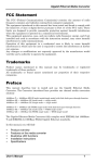
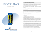
MC-MM1002
10/100M Media converter series
USER’S MANUAL
Copyright statement
This publication may not be reproduced as a whole or in part, any way what
so ever unless prior consent has been obtained from us.
FCC warning
The 10/100M series media converter have been tested and found to comply
with the limits for a Class A digital device, pursuant to Part 15 of the FCC
Rules. These standards are designed to provide reasonable protection against
harmful interference when these devices are operated in commercial
environment These devices can use, generate and radiate radio frequency
energy and may cause harmful interface to radio communications unless
installed in accordance with this User’s Guide. Operation of this device in a
residential area is likely to cause harmful interface which will make the user
responsible for the appropriate remedial action at his/her own expense.
operation status easily via a set of LED located in the front panel.
Package Content
1. MDI-MDIX Auto-crossover supported
2. Support flux controlling of full duplex/backpressure of half duplex
3. Comply to IEEE802.3 100Base-SX/LX &IEEE 802.3u 100Base-T
CE mark Warning
These are Class A products. In a domestic environment these products may
cause radio interface in which case the user will need to consider adequate
preventative measures.
4.
5.
Package Content
Thank you for purchasing our Ethernet Media Converter. Before
you start installing the Media Converter, verify the following items
in the package
1. Media Converter
2. User’s Manual
3. Power Adapter
10/100 Series Converter
The 10/100M Series 10/100BASE-TX to 100BASE-SX/LX converter is
1
primarily designed for larger and higher bandwidth demanding workgroups
that require expansion of the Ethernet network. The 10/100M features a RJ45
jack and a SC or SFP fiber optic connector, connecting the 10/100BASE-TX
network to the 100BASE-SX/LX (fiber optic) network. At full duplex mode,
the converter can extend distance up to 550 meters for Multi-mode fiber and
up to 80 kilometers for Single-mode fiber. It is fully compliant with IEEE
802.3u & 802.3 standards. The Installation & operation procedures of the
10/100M Series are simple & straightforward. User can monitor the real time
Work wavelength 850nm、1310nm、1550nm optional
Link between RJ45 and fiber port, dynamic data transmission, full/half
duplex, speed lights indication
6. Supply Slot, internal power and external power , UTP port supports
10/100M auto-negotiation
Cable Connection of 10/100M Series Converter
Port type
Max.Length
Cable Type
10/100BASE-T
Cat. 5, 5E UTP, RJ-45
100 meters
100BASE-SX
Multi-mode Fiber of 850n (62.5/125μm)
220 meters
100BASE-SX
Multi-mode Fiber of 850nm (50/125μm)
550meter
100BASE-LX
Single-mode Fiber of 1310nm(9/125um)
10-100km
2
LED Indication
Please refer to the following table for LED indication of 10/100M Series
Converter
LED
Status
Indication
PWR
ON
The Power is on
ON
Ethernet Speed is 100M
Off
Ethernet Speed is 10M
SPD
Off
No connection
ON
A valid network connection established on Fiber port
ON
Full Speed
Off
half Speed
FXL
Flash
Fiber Data
TXL
Flash
UTP Data
FEF
FDX
Physical Description
INTERFACE
RJ-45 part x 1 (10/100 Mbps)
SC/SFP connector Fiber port x 1 (100 Mbps)
TP
CONNECTIONS
10/100BASE-T:UTP Category 5, 5E
FIBER
CONNECTIONS
100BASE-SX:62.5/125µm
or 50/125µm Multi-mode
fiber, SC/SFP connector
LED
INDICATIONS
PWR,FEF,FDX,FXL,TXL,SPD
MAX.DISTANCE
550m/220m
SFP fiber connector
10km and 20km,80km
POWER
Operating Temp:0~+70℃
Storage Temp:-40~+85℃
Humlblty:10~90% non-condensing
5V 1.2A
NET WELGHT
EMISSION
500 g
FCC Class A, CE
ENVIRONMENT
1X9 fiber connector
100BASE-LX:9 or
10/125µm Single-mode
fiber ,SC/SFP connector
3
Specifications of 10/100M Series Converter
MODEL
1、10/100M Series
2、10/100M Series
STANDARD
IEEE802.3u
100BASE-T;
IEEE802.3
100BASE-SX
IEEE802.3u
100BASE-T;
IEEE802.3
100BASE-LX
4
Typical Optical Power Budget
10/100M Series
Connector
SC
SC
SC
SC
SC
Type
Wavelength
850nm
1310nm
1310nm
1310nm
1550nm
Typical
Distance
Optical
550m/220m
20Km
40Km
60Km
80-100Km
≥-12dBm
≥-14dBm
≥-11dBm
≥-6dBm
≥-5dBm
≤-23dBm
≤-34dBm
≤-36dBm
≤-38dBm
≤-38dBm
power
Sensitivity
4-ON 5-OFF, straightforward mode
6.LFPT function:ON-open;OFF-close
Notice: when start up LFPT function, please pay attention to set the DIP switch
6 to “ON” firstly, then power on the product.
Installation
Setting of Media Converter
Our media converter has DIP switch as follows:
Diagram 2-5
․Set with DIP switch
․Set RJ45 port in full duplex/half duplex or auto-negotiation
․Set RJ45 port at 10Mbps、100Mbps or 10/100Mbps
The DIP switch in front panel is marked 1-6 from left to right, the definition
of the setting is as below
1
2
3
Function
OFF
OFF
OFF
Auto-negotiation(default setting)
ON
OFF
OFF
Compelling 100M full duplex
5
ON
OFF
ON
Compelling 100M half duplex
ON
ON
ON
ON
OFF
ON
Compelling 10M full duplex
Compelling 10M half duplex
4 ,5-mode setting
4-OFF 5-OFF, store-and-forward mode(default setting)
As with any electric device, you should place the equipment where it will not
be subject to extreme temperatures, humidity, or electromagnetic interference.
Specifically, the site you select should meet the following requirements:
Please follow the steps to install the media converter. This Converter is a
plug-and-play device.
1. Turn off the power of the device/station in the network in which the media
converter will be installed.
2. Ensure that there is no activity in the network.
3. Attach fiber cable from the media converter to the fiber network. The fiber
connections must be Matched-Transmit socket to receive socket
4. Attach a UTP cable from the 100Base-Tx network to the RJ-45 port on the
product
5. Connect the power cord to the media converter and check if the power
LED lights up. The TP Link and FX link LED will light when all the cable
connections are satisfactory.
6. Turn on the power of the device/station.
6