1
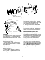
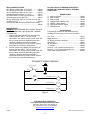
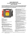
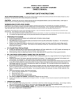
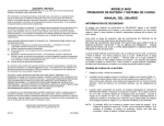
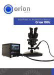
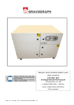
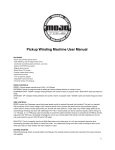
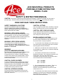
ACE INDUSTRIAL PRODUCTS
PORTABLE FUME EXTRACTOR
MODEL 73-200
SAFETY & INSTRUCTION MANUAL
CAUTION: This device is powered by rotating electrical machinery!! Careless or improper use may result in
personal injury. Read the Safety Precautions and Warnings contained within prior to operating this machine.
READ AND SAVE THESE INSTRUCTIONS.
SAFETY WARNINGS & CAUTIONS
CAUTION: (LIFTING)
FAILURE TO OBSERVE THE FOLLOWING
PRECAUTIONS COULD RESULT IN SERIOUS
INJURY, INCLUDING DEATH IN EXTREME CASES.
SAVE THESE INSTRUCTIONS.
This unit weighs more than 40 lbs. with filters, improper
lifting or handling of this unit could cause back injury.
CAUTION: (AIR FLOW BLOCKAGE)
Since exhaust air leaves the bottom of this unit,
caution should be observed not to set unit down in
such a way as to block the exhaust.
WARNING: (EXPLOSION HAZARD)
This unit contains universal motors which spark during
normal operation. Do not use in areas contaminated
by volatile or flammable materials as these sparks may
ignite the contaminates and cause a dangerous
explosion.
MISCELLANEOUS CAUTIONS:
1. Use of any attachment no recommended or sold
by the air cleaner manufacturer may result in risk of
fire, electric shock, or injury to persons.
WARNING: (EXPLOSION HAZARD)
This machinery is not suitable for collection of
combustible metal as listed in NFPA 484, which
includes: Aluminum, Titanium, Magnesium, Lithium,
Niobium, and Zirconium.
2. To reduce the risk of damage to the electric plug or
cord, disconnect by pulling plug rather than cord when
removing power form the air cleaner.
WARNING:
(VOC’S & AIRBORNE MICROBES)
3. Make sure cord and hose are located so they will
not be stepped on, tripped over, or otherwise subjected
to damage or stress.
The filters used in this unit will remove solid particulate
ONLY, and will not eliminate Volatile Organic
Compounds (VOC’s) or airborne microbes (bacteria,
mold & viruses) that may be a health hazard. Failure
to observe the presence of such fumes could cause
serious illness or death.
4. An extension cord should not be used unless
absolutely necessary. Use of improper extension cord
could result in risk of fire and electric shock.
If extension cord must be used, use only a grounded
cord and follow these recommendations:
CAUTION: (SHOCK HAZARD)
25 ft. #14 AWG
50 ft. #12 AWG
100 ft. #10 AWG
To insure continued protection against shock hazard,
connect A.C. cord only to properly grounded outlets.
Replace defective cords immediately. Don't expose to
moisture or liquid as this could defeat the electrical
insulation thus causing electrical shock.
5. Do not disassemble the air cleaner. Take it to a
qualified serviceman when service or repair is
required. Incorrect reassembly may result in risk of
electric shock or fire.
CAUTION: (STRONG VACUUM)
Care must be taken to avoid personal injury by not
allowing hose inlet to contact any body area such as
eyes, ears, mouth, etc.
6. To reduce the risk of electric shock or bodily injury,
unplug the air cleaner from outlet before attempting
any maintenance or cleaning. Turning off the power
switch will not eliminate this risk.
1
THEORY OF OPERATION
This unit is a lightweight, portable air cleaner
employing two thermally protected, high performance,
flow through vacuum motors producing very high
velocity air flow through the unit. By utilizing a large (2
1/2") inlet plus a variety of collecting nozzles and
fittings, fine solid particulate material and smoke may
be removed from the air by the filter media.
UNPACKING
Carefully inspect the unit for concealed damage that
may have occurred during shipping and handling. If
any damage is found, immediately contact the freight
company. Make sure that there are no dents in the
housing, as they will prevent the filters from sliding into
the units smoothly. If there is no evidence of damage,
remove the end cover by releasing the two rubber
latches. Removal of the front cover will allow
inspection of the inside of the unit.
An initial spark trap collects large particles before they
reach the pre-filter. An easy to empty tray is attached
to the front cover to enable the removal of the large
particles collected by the spark trap without removing
the filters. This trap further isolates the filters from
sparks in the case of a welding operation.
After unpacking the machine, check to see that the
following parts and accessories are present:
(1) 10’ Flexible Hose
(1) Flexible Metal Hose/Magnetic Base
Component Parts. (See Figure 2 For Individual
Parts Included)
(1) Slot Nozzle
(1) Pre-filter
Upon leaving the trap, the air is passed through a one
inch (1") thick, 20 - 35% efficient pre-filter. This
pre-filter is designed to catch the larger particles
leaving the trap. This relatively inexpensive pre-filter
prevents the more expensive main filter from becoming
quickly clogged. The pre-filter may be changed
several times before the main filter needs to be
changed.
INSTALLATION (See Figure 1)
1. Unpack a main filter and note the main filter has a
1/8" thick black rubber gasket on the outlet end.
Please also note that the filter has an airflow
direction arrow placed on one of the edges. Insert
the filter, gasket first, into the machine with the
arrow pointing toward the rear of the unit, away
from the inlet end. Make sure that the filter media
folds run vertically. If they do not, remove the filter
and rotate it 90°.
2. Place the pre-filter directly against the main filter
with the wire supported side toward the main filter
and the media folds again running vertically.
3. Replace the front cover/spark trap assembly and
re-latch the cover using the rubber latches.
4. Connect the unit to the power source and test the
operation of the unit by turning it ON with the
On/Off switch. Should the motors not start, or
should the machine make unusual noises,
immediately turn the machine off and seek trained
maintenance personnel. Once the test is
complete, turn the unit back OFF.
5. Attach the hose to the inlet.
6. Assemble the flexible metal hose and nozzle per
Figure 2.
7. Connect the hose/nozzle combination assembled
in Step 6 above to the machine with the 10' flexible
hose and the supplied coupling.
All factory furnished filters have a U.L. class II
rating and using any filters other than those
specified for this unit is not recommended.
Use of any product other than that recommended by
the manufacturer will void the warranty.
The main (or final) filter may be selected from three (3)
grades available, depending upon the level of
performance desired. All of these are high efficiency
multi-flow filters which feature extended surface area
for long life in high velocity filtration systems.
Selection of the filter best suited for the job should be
discussed with a dealer or a factory representative.
A "clogged" filter light, actuated by a differential
pressure switch is an integral part of the unit. When
the filters become clogged, the light will illuminate. At
this point, the filters should be changed. Depending
upon the application, the pre-filter can be changed
several times before the main filter must be changed.
Changing the pre-filters regularly can extend the useful
life of the final filter up to 50%.
GENERAL MAINTENANCE
This completes the basic assembly of your unit.
Depending upon the accessories ordered and the
logistics of the work place, the installation configuration
may vary.
ONLY QUALIFIED SERVICE TECHNICIANS
SHOULD MAKE REPAIRS TO THIS UNIT.
DO NOT REPLACE THESE MOTORS WITH
MOTORS OTHER THAN THOSE RECOMMENDED
BY THE MANUFACTURER.
2
4
6
2
1
5
7
3
PRE-FILTER
INSTALL PLEATS VERTICALLY
AS SHOWN
Figure 1
FLAT FIBER WASHER
(2 EA)
FLEX TUBE ASSY
(1 EA)
5. Upon completion of the specific manufacturing or
welding operation, turn the machine off. Continuous
running of the nit will reduce the life of the filter and the
motor brushes as well as increase utility cost.
6. When the “clogged” filter light indicated that the
filter is clogged, turn the machine off and remove
power cord from its power source.
SPLIT-LOCK WASHER 1/4"
(2 EA)
WING NUT 1/4-20
(2 EA)
HEX HEAD BOLT 1/4-20 X 3/4
(1 EA)
See the section on installation and use the reverse
process to remove the dirty filters. Reinstall the new
filter and reconnect the machine to its power source.
BRACKET HOSE SUPPORT
(1 EA)
SUPPORT LEG
(1 EA)
MAGNETIC BASE
(1 EA)
STEEL FLAT WASHER 1/4"
(1 EA)
MAINTENANCE & REPLACEMENT PARTS
FILTERS:
As previously stated in the “Theory of Operation”
section of this manual, the “clogged” filter indicator light
will light whenever the differential pressure across the
filter indicates that the filter is clogged. When opening
the unit, there are no vacuum hoses to disconnect
since the pressure sensing is accomplished by
measuring at the inlet and inside the suction chamber.
The differential pressure trip point is preset and is not
field adjustable.
RECTANGULAR NOZZLE
(1 EA)
HEX NUT 1/4-20 KEPS
(1 EA)
Figure 2
OPERATION
Your Ace Industrial Products machine is designed as a
source capture device, i.e., it is intended to eliminate
smoke and particulate at their point of origin. Keeping
this in mind, the machine should be operated in the
following manner:
Reread the section on Safety Warnings & Cautions
before proceeding any further.
1. Place the machine on a flat, level surface. Pick a
location that will allow unrestricted flow of the exhaust
air to the atmosphere.
2. For units with wheels or casters, lock the wheels or
block the wheels.
3. Place the collection nozzle as close to the work as
practical without interfering with the operator. Secure
the nozzle if necessary.
4. Using the ON/OFF switch, turn the machine on.
Should the not start, or should make unusual noises,
immediately turn the machine off and seek trained
maintenance personnel. Do not continue to use the
unit.
If the “clogged” filter light should light, the pre-filter
should be changed first, since it is the less expensive
of the two. By changing the pre-filter on a regular
basis, the main filter will last up to 50% longer in
most applications. If the light still lights after the prefilter is changed, the main filter is clogged and must be
changed.
3
REPLACEMENT FILTERS
65% Efficiency Main Filter 12”X12”X12” .............. 65008
95% Efficiency Main Filter 12”X12”X12” .............. 65009
99.97% HEPA Main Filter 12”X12”X12”............... 65010
Extended Surface Pre-Filter (3.2 sq ft) ................ 65011
Aluminum Mesh Pre Filter (oil mist control) ......... 65013
Charcoal (odor control) Pre Filter......................... 65037
99.97% HEPA Main Filter 12”X12”X12” (for use with
(6) 65037 Filters).................................................. 65042
Charcoal filter with Zeolyte (neutralizes nitric oxide)......
............................................................................. 65044
DO NOT REPLACE THESE MOTORS WITH A
MOTOR THAT DOES NOT HAVE A THERMAL
OVERLOAD!!!
1)
2)
3)
4)
5)
6)
7)
MAINTENANCE:
WARNING: MAINTENANCE ON THIS UNIT SHOULD
BE PERFORMED ONLY BY QUALIFIED, TRAINED
TECHNICIANS.
1. Motor brushes are available from the factory by
ordering Part No. 65077. The use of high
performance, ball sleeve motors provide about 500
hours of brush operation (depending upon filter
condition). Brushes should be periodically
checked after 500 hours use and if worn, replace
as a matter or preventative maintenance.
2. Vacuum motors are available from the factory by
ordering Part No. 65077. The use of high
performance, ball sleeve motors provide about 500
hours of brush operation (depending upon filter
condition). Brushes should be periodically
checked after 500 hours use and if worn, replace
as a matter of preventative maintenance.
REPAIR PARTS
Motor w/ screws................................................ 65001
Motor Gasket .................................................... 65002
Rubber Latch .................................................... 65003
Clogged Filter Indicator Light............................ 65004
ON/OFF Toggle Switch .................................... 65005
Differential Pressure Switch ............................. 65006
Motor Brushes .................................................. 65077
ACCESSORIES
The following accessories and attachments are
available from the factory or from your Ace dealer
Flex Tube ................................................................ 65012
Magnetic Base ........................................................ 65014
10’ Extension Hose & Coupling .............................. 65017
Slot Nozzle .............................................................. 65019
20” Slot Nozzle........................................................ 65036
“T” Adapter .............................................................. 65040
Reducer, 1-1/4” (Smoke Extracting Gun)................ 65041
Reducer, 1-1/2” (Smoke Extracting Gun)................ 65043
Power-Matic Inductive Switch ................................ 99-800
SCHEMATIC WIRING DIAGRAM
POWER SWITCH
OFF
ON
VACUUM
SWITCH
"CLOGGED" FILTER
R
VACUUM MOTOR #1
M
VACUUM MOTOR #2
M
Figure 3
ACE INDUSTRIAL PRODUCTS
From Associated Equipment Corporation
5043 Farlin Avenue St. Louis, MO 63115
Tel. (314) 385-5178 Fax. (314) 385-3254
www.aceindustrialproducts.com
X2268
REV. 12/02/2011 9027-0371
4