1
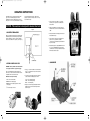
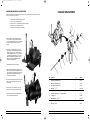
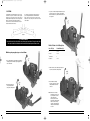
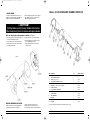
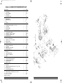
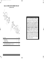
Gates428-7149_V7:Gates428-7149-V7
10/5/07
7:39 AM
Page 1
428-7149
12/04
Model 6-32 HOSE CUT-OFF MACHINE
OWNER’S MANUAL
For 6-Wire Spiral &
2-Wire Braid Hose through 2” I.D.
CUTTER
Part Number:
78018
Product Number:
7480-6597
SCALLOPED-EDGE
REPLACEMENT BLADE
Part Number:
78003
Product Number:
7482-1329
Gates428-7149_V7:Gates428-7149-V7
10/5/07
7:39 AM
Page 2
SAFETY INSTRUCTIONS
! WARNING
SPECIFICATIONS
FEATURES:
Power Source:
3 H.P. (5.2 H.P. Peak )
• Cuts up to 2” I.D. two-wire braid
through six-spiral reinforced hose.
SINGLE PHASE
• 230V
• 60 Hz
• 15 Amp motor
• Reversible 10” scalloped-edge, highspeed steel blade with 3⁄4” bore. Blade
can be sharpened.
THREE PHASE
• 460V
• 60 Hz
• 15 Amp motor
If a 460 volt source is used, it will be
necessary to change connections as
shown on motor name plate and
replace 230 volt heaters in manual
starter with 460 volt heaters.
• Radius hose feed into blade for
reduced friction.
• OSHA approved inner blade guard for
safe operation.
• Includes Coolant Spray System Kit for
reduced heat in high-capacity cutting
applications (recommended for multibraid and spiral reinforced hose). Kit
includes reservoir, spray nozzle and
mounting hardware.
Avoid serious injury. Before using this
power saw, follow these instructions:
1. Read and follow the user manual.
2. Protect your eyes with safety glasses or face shield.
3. Do not wear loose clothing – it can get caught in the
moving blade.
4. Keep hands away from the moving blade.
5. Turn off power with lockout before adjusting or
servicing saw.
6. Use saw only if the blade guard is installed.
7. Fasten saw to work surface before use.
(See mounting instructions.)
8. Use only to cut hose and do not use a dull blade.
9. Support hose on front plate and pins.
10. Use only the special scalloped 10 inch blades –
other blades may injure you or damage the saw.
Dimensions:
HOSE CUT-OFF MACHINE
22” Wide by 42” Length by 24” High
The Gates Corporation
Denver, CO 80202 303-744-5291
Weight:
215 lbs.
MORE HELPFUL TIPS:
• Before using this saw, remove all tools from the cutting table and from around the saw.
• Do not overload or use machine for other than intended purpose.
• Do not force hose into blade. The motor may stall and burn out and the blade may break.
• While cutting, apply light, steady pressure to cutting handle.
Si no entiende Ud. este mensaje, es obligatorio por su seguridad de
obtener de Gates estos avisos y instrucciones en español.
En cas de difficulté de comprehension de ces conseils,
on est obligé pour la sécurité de demander de Gates un document contenant
ces avis et instructions en français.
Model 6-32 HOSE CUT-OFF MACHINE OWNER’S MANUAL
Page 2
Model 6-32 HOSE CUT-OFF MACHINE OWNER’S MANUAL
Page 3
Gates428-7149_V7:Gates428-7149-V7
10/5/07
7:39 AM
Page 4
OPERATING INSTRUCTIONS
The Model 6-32 hose cut-off machine will cut all
types of hose including high pressure 2-wire
braided hose and some multi-spiral hose in sizes
through 2” I. D. It is not recommended to cut spiral
hose with interwoven helix wire. When used
properly, it produces a straight, clean cut on any
hose within its range.
NOTICE – This machine is designed for manual feed only.
Figure 1
1. MOUNTING THE MACHINE
4. Connect other side of cable to 6-32 saw by
removing cover of power box containing the
starter switch.
5. Strip outer insulation on electrical cable and
insulation from each of the four wires within the
cable.
6. Punch perforated hole through power box and
thread cable through.
Before operating this machine it must first be firmly
bolted through the four mounting holes (located on
the base flanges) to a bench or stand so that two
sides are accessible to the operator. (See Figure 1.)
7. Connect the two hot and one neutral wires to
power box. The ground wire should be
connected to the grounding lug as illustrated in
the photo at right.
8. Install locking power cord plug NEMA L14-20-P
to a 15 or 20 amp NEMA L14-20-R electrical
circuit. Be sure circuit is grounded and complies
with all local electrical codes.
3. COMPONENTS
2. INSTALL POWER CORD PLUG
WARNING: Have a qualified electrician install the
correct plug and outlet for your power supply.
Saw can be hard wired or wired with a plug. In
either case, contact a licensed electrician to ensure
compliance with local electrical codes.
Materials needed (not included):
• 14/4 or 12/4 electrical cable
• NEMA L14-20-P locking plug
• NEMA L14-20-R locking receptacle to match
locking plug
•
⁄4” Romex clamp connector
3
Model 6-32 HOSE CUT-OFF MACHINE OWNER’S MANUAL
1. Strip 1-1⁄2” of outer insulation on electrical cable.
Strip 1⁄2” of insulation from each of the four wires
within the cable.
2. Connect each of the three wires in the electrical
cable to the disassembled plug as follows:
Green – “G” terminal (ground)
White – “W” terminal (neutral)
Black – “X” terminal (hot)
3. Replace outer shell of plug and tighten with two
Phillips-head screws. Slide and snap moisture
barrier in place.
Page 4
Model 6-32 HOSE CUT-OFF MACHINE OWNER’S MANUAL
Page 5
Gates428-7149_V7:Gates428-7149-V7
10/5/07
7:39 AM
Page 6
COOLANT SPRAY SYSTEM
4. INSTALLING THE WATER COOLANT SYSTEM
To reduce heat and friction on blade and increase blade life, it is recommended you install the water coolant
system. Contents of box are as follows:
• 1 each lubricator with bracket (Part No. 68387)
• 1 each 1⁄4” copper coolant spray tube
• 2 each #10 – 32 X 1⁄2” round head bolts (Part No. VH03CD)
• 2 each #10 – 32 hex nut (Part No. VH15C)
• 2 each #10 – 32 lock washer (Part No. VH35D)
A. Unpack lubricator contents and check that all
parts are in the container. Install lubricator by
removing the Phillips head screws on the top and
bottom of the belt shroud. Remove the belt
shroud.
B. Locate the four pre-drilled holes on the belt
shroud of the 6-32 saw. Attach bracket (Part No.
68387) using the two bolts, washers and hex
nuts provided (Items #8, 9, and 10 on illustration
on next page) through the top two holes of the
lubricator mounting bracket and the top two
holes of the belt shroud. (Additional holes
available for added support.)
C. Re-install belt shroud (reverse steps A).
D. Install Coolant Spray Tube by locating shut-off
valve on lubricator (Item #3 of illustration on next
page). Remove bite nut and bite sleeve (Item #5)
from shut-off valve. Install provided copper
coolant spray tube (Item #6).
ITEM
DESCRIPTION
QTY.
PART NO.
1
LUBRICATOR WITH BRACKET
1
68387
2
NEEDLE VALVE (water supply)
1
68389
3
SHUT-OFF VALVE (Lubricator)
1
68645
F. Insert the other end of the tube into the spray
port (located on the top of the blade shroud).
4
BUSHING – 3⁄8” x 1⁄4”
2
VA12CBA
5
COMPRESSION CONNECTOR – ⁄4” MPT x ⁄4” BITE SLEEVE AND NUT
1
VA14BCE
G. Connect water supply using 1⁄4” MPT and bite
sleeve to lubricator water inlet port.
6
COOLANT SPRAY TUBE – 1⁄4” COPPER TUBING
1
16736
7
COUPLING – ⁄4”
1
VA16BA
8
MACHINE BOLT – #10-32 x 1⁄2”
2
VH03CD
9
LOCK WASHER – #10-32
2
VA35D
HEX NUT – #10-32
2
VH15C
E. Position provided coolant spray tube by bending
tube for routing through the port on top of the
blade shroud.
10
Model 6-32 HOSE CUT-OFF MACHINE OWNER’S MANUAL
Page 6
1
1
1
Model 6-32 HOSE CUT-OFF MACHINE OWNER’S MANUAL
Page 7
Gates428-7149_V7:Gates428-7149-V7
10/5/07
7:39 AM
Page 8
5. CUTTING
A cutting table is provided with five sets of holes
for the two hose pins. Smaller hose sizes require
the pins to be in a position closer to the center of
cutting table than larger hose sizes as depicted in
Figure 2. Experience will enable operator to
select which set of holes will work best for each
size and reinforcement of hose.
It is possible to square up a ragged end on a
piece of larger diameter hose with minimum
waste. Place one hose pin in one of the center
table holes. Place other pin in outer hole on other
side of table.
3. Lay hose on table and push handle into hose to
bend to proper arc for cutting. (See Radii of
Bends Chart below.) Ratchet will hold hose in
this position.
Figure 2
∆ CAUTION!
Hose should never be forced into blade or cut without proper bend radius. Forcing hose into blade
will cause excessive friction heat which will reduce blade life and may cause blade to break.
Radii of Bends for Cutting Hose
With hose pins properly set, proceed as follows:
Hose I.D. (In.)
Bend Radius (In.)
2
6 to 8
3
1 and ⁄4
2 to 4
1
⁄2 & Smaller
1
1
1 ⁄2 and 1 ⁄4
1
4 to 6
1. The cutting table should be away from blade in
loading position with table stop engaged and
motor switch off.
4. Start machine, release table stop and push
hose into blade with cutting handle.
5. Return table to loading
position, stop motor, release
cutting handle and remove
cut hose.
2. Lift ratchet knob and
swing cutting handle
away from cutting table.
Note: Small sizes of fabricbraided hose may be cut
by having table locked
and pushing hose
between pins and into
blade with cutting handle.
When used in this way,
ratchet is disengaged by
lifting knob and turning it
1/4 turn.
Model 6-32 HOSE CUT-OFF MACHINE OWNER’S MANUAL
Page 8
Model 6-32 HOSE CUT-OFF MACHINE OWNER’S MANUAL
Page 9
Gates428-7149_V7:Gates428-7149-V7
10/5/07
7:39 AM
Page 10
Model 6-32 CUT-OFF BRACKET ASSEMBLY PARTS LIST
6. BLADE CHANGE
Over time the cutting blade will dull. Do not cut
hydraulic hose with a dull blade. New blades are
available through Gates (order Part Number
78003/Product Number 7482-1329 for scalloped
edge). Blades can also be re-sharpened. See
“Blade Re-Sharpening Procedure."
∆ CAUTION!
Cutting blades are very sharp. Handle with caution.
Wear heavy-duty gloves to remove and replace blades.
Blade can easily be removed from machine as follows: (See Figure 4.)
1. Unscrew the (3) screws holding blade guard and
remove from blade guard assembly.
2. Loosen and remove hex nut from blade shaft.
3. Carefully remove washer, drive disk and blade
from blade guard bracket.
4. Replace with a new or re-sharpened blade.
5. Re-install drive disk, washer and hex nut on
drive shaft and tighten securely.
6. Replace blade guard and secure with (3)
mounting screws.
Figure 4
BLADE RE-SHARPENING PROCEDURE
A blade re-sharpening service is available through
Curtis-Toledo’s facility in St. Louis, Missouri.
Model 6-32 HOSE CUT-OFF MACHINE OWNER’S MANUAL
Contact Curtis-Toledo’s customer service
department by phone at 314-383-1300 or by
fax 314-381-1439 or e-mail at [email protected].
Page 10
ITEM
DESCRIPTION
QTY.
PART NO. / PROD. NO.
1
2
3
4
5
6
7
8
8
9
10
11
12
13
CUT-OFF BLADE GUARD
CUT-OFF BLADE BRACKET
SCREW, 1⁄4”-20 X 7⁄8” LG.
LOCKWASHER, INTERNAL TOOTH 1⁄4”
NUT, 5⁄8”-11 NC LH HEX
WASHER, 115⁄16” OD X 5⁄8” ID X .070” THICK
FLANGE, OUTSIDE
CUT-OFF BLADE, BEVEL EDGE
CUT-OFF BLADE, SCALLOPED EDGE
FLANGE, INSIDE
RING, RETAINING
BEARING
SHAFT, CUT-OFF BLADE
BEARING
1
1
3
3
1
1
1
1
1
1
1
1
1
1
*
*
26617
4131
15968
27029
15943
15960
78003/7482-1329
19320
16790
15963
20914
13591
* Sold as assembly only, part number 21393 (Includes items 1,2,3 & 4)
Model 6-32 HOSE CUT-OFF MACHINE OWNER’S MANUAL
Page 11
Gates428-7149_V7:Gates428-7149-V7
10/5/07
7:39 AM
Page 12
Model 6-32 HOSE CUT-OFF MACHINE PARTS LIST
ITEM
DESCRIPTION
1
BASE
2
CUTTING TABLE
3
PIVOT PIN ASSEMBLY
4
RATCHET PAWL
5
RATCHET PAWL SPRING
6
WASHER
7
RETAINING RING
8
RATCHET PAWL KNOB
9
PIN
10
HOSE PIN
11
TABLE STOP
12
SHOULDER SCREW, SOCKET HD., 5⁄16” X 5⁄8” LONG
13
CUT-OFF ARM
14
HANDLE ASSEMBLY
15
RATCHET PLATE
16
SCREW, 5⁄16”-18 X 3⁄4” SOCKET HD. CAP
17
CUT-OFF BRACKET ASSEMBLY
18
SCREW, HHCS 3⁄8”-16UNC X 11⁄4” GRADE 5
19
LOCKWASHER 3⁄8” INTERNAL TOOTH
20
WASHER, PLAIN, SAE 1”
21
MOTOR, 230/460V, 3 PHASE
21
MOTOR, 230V, SINGLE PHASE
22
SCREW, HHC 3⁄8”-16 X 1” LONG, GRADE 5
23
BRACKET, STARTER
24
STARTER, 230V, 3 PHASE
24
STARTER, 460V, 3 PHASE
24
STARTER, 230V, SINGLE PHASE
25
LOCKWASHER
26
SCREW, 10-24 X 5⁄8” LONG, RHMS
27
WASHER, REDUCING, 3⁄4” X 1⁄2”
28
CONNECTIN, ANGLE, SQUEEZE BOX, 1⁄2” 90°
29
INSULINER
30
CONDUIT, FLEXIBLE STEEL, 1⁄2”
31
CONNECTOR, 1⁄2” SQUEEZE, 45°
32
ELBOW
33
BRACKET, BELT GUARD
34
PULLEY, MOTOR (SINGLE PHASE UNITS)
34
PULLEY, MOTOR (3 PHASE UNITS)
35
PULLEY, BLADE SHAFT
36
BUSHING, 5⁄8” BORE
37
V-BELT
38
BELT GUARD
39
SCREW,THREAD CUTTING, PAN HD., TYPE “F” 10-24 X 3⁄8” LONG
40
WASHER, CUT, FLAT 1⁄4”
41
LOCKWASHER, INTERNAL TOOTH 1⁄4”
42
SCREW, #14 X 3⁄4” SLOTTED, HEX, WASHER HD., S.M.S.
43
SCREW, SOCKET HD., CUP POINT, SET 1⁄4”-20 X 1⁄2” LONG
44
KEY, 1⁄4” X 1⁄4” X 23⁄4” LONG
45
KEY, 3⁄16” X 3⁄16” X 11⁄2” LONG
*Available as assembly only
Model 6-32 HOSE CUT-OFF MACHINE OWNER’S MANUAL
QTY.
PART NO.
1
1
1
1
1
1
1
1
1
2
1
1
1
1
1
2
1
3
7
3
1
1
4
1
1
1
1
4
2
1
1
2
1
1
1
1
1
1
1
1
2
1
2
2
5
2
1
1
1
20907
15927
16012
*13741
13744
26973
*
*15956
15929
15065
15928
13833
15946
8319
21393
VH12KK
4906
VH33X
21135
21136
VH12KH
26621
27837
27842
27838
12037
4443
VE614
VE605
12490
18850
11894
VA08DP
24527
26640
23952
23951
20909
23950
24528
7464
VH32F
VH38F
68705
7207
16001
5149
Page 12
Model 6-32 HOSE CUT-OFF MACHINE OWNER’S MANUAL
Page 13
Gates428-7149_V7:Gates428-7149-V7
10/5/07
7:39 AM
Page 14
Model 6-32 INNER GUARD ASSEMBLY PARTS LIST
(Part Number 26692)
Two-Year Limited Warranty on Equipment*
For two years from the equipment ship date to the original
user, Gates Corporation will, at its option, replace or repair
any unit which proves to be defective in material or
workmanship, or both, at no cost to the original user of the
equipment. This is the exclusive remedy. THERE IS NO
OTHER EXPRESS OR IMPLIED WARRANTY. ALL
INCLUDING THOSE OF MERCHANTABILITY AND FITNESS
FOR A PARTICULAR PURPOSE, ARE LIMITED TO ONE
YEAR FROM DATE OF SHIPMENT OF THE EQUIPMENT TO
THE ORIGINAL USER. LIABILITY FOR CONSEQUENTIAL
AND INCIDENTAL DAMAGES UNDER ANY AND ALL
WARRANTIES IS EXCLUDED TO THE EXTENT EXCLUSION
IS PERMITTED BY LAW. Some states do not allow the
exclusion of incidental or consequential damages, and some
states do not allow limitations on how long an implied
warranty lasts, so the above limitation and exclusion may not
apply to you. This warranty gives you specific legal rights
and you may also have other rights which vary from state to
state. For warranty service, contact Service Department,
Gates Corporation, P.O. Box 5887, Denver, Colorado 80217.
ITEM
DESCRIPTION
QTY.
PART NO.
1
2
3
4
5
6
7
INNER GUARD, RIGHT
INNER GUARD, LEFT
SPRING-INNER GUARD
GUARD BUTTON (ROLLER)
SCREW, MACHINE, ROUND HEAD 10-24 X 3⁄8” LG.
SCREW, SOCKET, BUTTON, HEX HEAD CAP 1⁄4”-20 NC X 1⁄2” LG.
SCREW, SOCKET, BUTTON, HEX HEAD CAP 1⁄4”-20 NC X 5⁄8” LG.
1
1
4
8
4
4
4
26674
26673
26983
26667
14479
26670
14774
Model 6-32 HOSE CUT-OFF MACHINE OWNER’S MANUAL
Page 14
*Blade is not covered by any warranty.
Gates428-7149_V7:Gates428-7149-V7
10/5/07
7:39 AM
Page 16
A Tomkıns Company
Gates Corporation
1551 Wewatta Street
Denver, CO 80202
www.gates.com