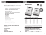
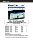
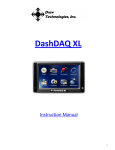
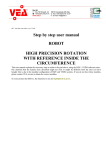
1
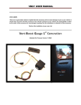
VBG1 USER MANUAL DISCLAIMER: This gauge is in no way approved by Subaru or Fuji Heavy Industries. There are no guarantees stated or implied that this accessory will not cause damage to you or your vehicle. It should also be known that this accessory may void the warranty to your vehicle. No responsibility is taken by the seller of this accessory for any damages resulting from the installation or utilization of this accessory. Perform this installation at your own risk. Vent Boost Gauge 1st Generation [Updated for Firmware Version 1.05b4] VBG1 USER MANUAL Table of Contents VBG1 Quick reference: ..................................................................................................................................................3 VBG1 Overview: .............................................................................................................................................................4 VBG1 specifications: ......................................................................................................................................................4 Inputs: ...................................................................................................................................................................4 Instrumentation: ...................................................................................................................................................4 *Auxiliary input options (ONLY ONE CAN BE SLECTED): .......................................................................................4 Installing the VBG1 in the vent: .....................................................................................................................................5 Powering up the sending unit:.......................................................................................................................................6 Routing Vac/Boost tubing ..............................................................................................................................................6 Monitoring AFR with the VBG1: ....................................................................................................................................7 AFR Via LC-1 Configuration: ......................................................................................................................................7 AFR LC-1 Wiring .........................................................................................................................................................7 AFR Via PLX SM-AFR Configuration: ..........................................................................................................................8 Analog Auxiliary input options:......................................................................................................................................8 Getting started: .............................................................................................................................................................9 Changing the right screen display mode: ................................................................................................................10 Requesting peak recall: ...........................................................................................................................................10 Configuration Menu: ...................................................................................................................................................11 Configuration menu – Quick reference ...................................................................................................................11 Configuration Details ...................................................................................................................................................12 Option 9 - AUX Display Option:...........................................................................................................................12 Option 11/12 - AUX plot max/min: .....................................................................................................................12 Option 22 - LED Boost Display Option: ...............................................................................................................13 ALARMS Configuration Menu: .....................................................................................................................................14 Alarms configuration menu – Quick reference .......................................................................................................14 ALARMS Configuration Details ................................................................................................................................14 Boost Alarm ........................................................................................................................................................14 AFR (AUX) Alarm .................................................................................................................................................14 TEMP(AUX) Alarm ...............................................................................................................................................14 PRESSURE (AUX) Alarm .......................................................................................................................................14 Volts Alarm .........................................................................................................................................................14 Additional Features .....................................................................................................................................................15 Blackout mode: .......................................................................................................................................................15 Custom Startup message: .......................................................................................................................................15 Additional Information ................................................................................................................................................16 More about the OLED displays: ...............................................................................................................................16 VBG1 version feature matrix: ..................................................................................................................................16 www.gtboostgauge.com rev 1.4 [Applies to VBG1 Ver. 1.05b4] Page 2 VBG1 USER MANUAL VBG1 Quick reference: WIRE COLOR RED BLACK GREEN YELLOW NAME +12 V – Accessory power* GROUND Parking Lights Input (+12V = Parking lights on) AFR Input** – LC1 Compatible (0 - 5V) DISPLAY UNIT 18 inch cable Pressure Line Hookup SENDING UNIT Aux Input Power, AFR, Parking Lights Hookup LED bar graph – Dedicated to Boost and Vacuum Ambient Light Detector Right to Left: Up to 24 PSI 1 LED per PSI Boost Display Left to Right: Up to 24 in/hg 1 LED per in/hg of Vacuum Used to auto-adjust Screen and LED Brightness Buttons (3) Capacitive touch sensors Dual OLED Display Button Indicators Left: Displays Vac, Boost and Peak Lights next to each button illuminate when pressed Right: Displays Boost / AFR/AUX*** Profile, AFR/AUX***, Volts *Accessory power timing relative to engine start is critical for proper operation, for more information see specifications section. **AFR output from compatible Air/Fuel Ratio Sensor Controller must be set correctly, see AFR section ***AFR/AUX only available if using compatible Air/Fuel Ratio Sensor Controller or approved AUX sensor. See “Auxiliary input details” section for more information. www.gtboostgauge.com rev 1.4 [Applies to VBG1 Ver. 1.05b4] Page 3 VBG1 USER MANUAL VBG1 Overview: Toggle Right Display Option Use top button to select to view: Boost Profile Numerical AFR/AUX w/ indicator AFR/AUX Profile Numerical Voltage w/ indicator Dedicated display Display Peak Automatically displays the following based on mode: Numerical Boost (unit PSI) Numerical Vacuum (unit In/Hg) Peak Boost history (last 5 peaks) – Profile displayed automatically in right screen User selectable display See Toggle Right Display option Use bottom button to select peak recall: Increment peak history # (1-5) If AFR/AUX is enabled – AFR/AUX profile will be displayed on second touch. VBG1 specifications: Inputs: Voltage AFR Input Parking lights input Instrumentation: Voltage accuracy Boost Pressure Range Vacuum Range Boost / Vacuum accuracy Vacuum resolution Boost resolution 12V – 18Volts 0-5 Volts 12V = Parking lights ON +/- 0.2 Volt 0 - 48 Psi (Bar graph Readout) 0 - 48 Psi (Numerical Readout) 0 - 25 InHg +/- 0.25 PSI (up to 30 PSI) 1 InHg 0.1 PSI *Auxiliary input options (ONLY ONE CAN BE SLECTED – includes digital PLX interface): AFR via LC1, PLX or Zt-2/3 OIL/FUEL PRESSURE TEMP PROBE Range 10-20 AFR Range 0 - 150 PSI Range -40 - 125 °C Accuracy ±0.1 AFR Accuracy ±5 PSI Accuracy ±2 °C Power should be sourced to the VBG1 before engine start, for most model years IGNITION power provides proper power sequencing. Some model years (07+) have some ignition lines that power off briefly at engine start. The atmospheric sampling sequence depends on proper power sequencing. Please be sure that the proper power sequencing is provided to the gauge. *AFR only available if using compatible AFR Sensor Controller Air/Fuel Ratio Sensor Controller must be set correctly, see AFR section. Specific Temperature probe or Oil/Fuel pressure sensor must be used. See “Auxiliary input options” section for more information. www.gtboostgauge.com rev 1.4 [Applies to VBG1 Ver. 1.05b4] Page 4 VBG1 USER MANUAL Installing the VBG1 in the vent: For detailed vent installation instructions specific for vehicle type please see www.gtboostgauge.com and follow the links to the VBG1-> installation section. Shown below are pictures from a 4th generation Legacy GT installation. Installation of the VBG1 is relatively easy. Remove the driver’s side vent from the dash and then remove the outer trim piece. Once the trip piece is separated remove the two top vent louvers from the vent. The VBG1 tabs will fit where the two top vent louvers were removed. Hook up the sending unit to the VBG1 before fitting it in the vent. Be sure that the black side of the flex cable is up, and then slide in the clip to lock. Bend the flex cable up and crease it so it hold the position shown above, this will make sure it doesn’t interfere with the directional vent louvers behind it. You may need to use a flat tool to pry the VBG1 into place. Be careful not to scratch the circuit board or the front face of the gauge. Once in place the flat flex cable should exit the vent as shown above. www.gtboostgauge.com rev 1.4 [Applies to VBG1 Ver. 1.05b4] Page 5 VBG1 USER MANUAL Powering up the sending unit: The sending unit requires a minimum of power and ground to be hooked up in order to operate the VBG1 as a boost/vac gauge. The VBG1 Power wire (RED) wire should be attached to the IG2 circuit. The easiest place to tap this circuit is at the fuse box using a fuse tap. Locate the appropriate location for your car using the back panel of the fuse cover as a guide. Wiring up the Parking lights circuit is optional. If you wish to wire this circuit then VBG1 Parking Lights Input wire (GREEN) should be wired to the ILM circuit at the fuse box. When the parking lights are on, this circuit goes to 12V and the VBG1 will dim its illumination. The VBG1 only has one dim level, and does not change variably with dash illumination settings. When the parking lights are on, the gauge dims. If the user drives with headlights on, it is recommended to use the ambient light dimming feature. Be sure to select the feature you wish to use in the configurations menu – option # 10. Fuse location for tapping IG2 circuit 2007-2009 Routing Vac/Boost tubing The sending unit should be hooked up to boost/vac tubing with an Inside diameter (ID) of .17” and a recommended outside diameter (OD) of 1/4". The recommended location for attaching the boost/vac tube would be at the Air By-pass Valve as shown below. The Air By-pass Valve mates to 1/4" (ID) Tube so a reducer T is used. A tube/fitting kit is available from the www.gtboostgauge.com/shop website. Stock www.gtboostgauge.com After install Tube / Fitting Kit rev 1.4 [Applies to VBG1 Ver. 1.05b4] Page 6 VBG1 USER MANUAL Monitoring AFR with the VBG1: The AFR display on the VBG1 relies on the analog output of an approved wide band meter. Approved analog interface meters are: Innovatemotorsports LC-1, Zeitronix Zt-2 or Zt-3. In addition to analog monitoring digital AFR monitoring is supported with the PLX SM-AFR gauge. AFR Via LC-1 Configuration: If using the LC-1 the meter must share the same ground; if possible it is best to tie the ground of the VBG1 to the ground of the LC-1. If not make sure that they are both tied to chassis ground. To assure accuracy of the AFR display on the VBG1 the output settings of the LC-1 must be configured as: 0V = 10AFR, 5V = 20AFR, Warm-up = 5V AFR LC-1 Wiring Here is a wiring diagram for the proper LC-1 hookup. Please double check all connections before powering up and be sure to refer to the LC-1 documentation to verify accuracy. Switched Power 12V VBG1 Switched Power 12V Analog 2 out SENDING UNIT LC1 = TIE POINT www.gtboostgauge.com rev 1.4 [Applies to VBG1 Ver. 1.05b4] Page 7 VBG1 USER MANUAL AFR Via PLX SM-AFR Configuration: VBG1 provides a digital interface that can decode the PLX SM-AFR Gauge protocol. This connection is a digital connection to the PLX gauge and should be made as follows: Connect the 3.5mm stereo (male to male) audio cable from the PLX SM-AFR (TX PORT [# 4]) to the VBG1 TX/RX port as shown. Be sure to enable “AFR-PLX” option in the configurations menu “AUX DISPLAY OPTION”. See page 11 of this manual for configuration information. Analog Auxiliary input options: One of the following approved accessories may be used with the single auxiliary input. The configurations menu option 9 “AUX Display Option” should be set to indicate which auxiliary device is being used. These auxiliary input devices are not included with the VBG1 but may be purchased from the www.gtboostgauge.com/shop website. Unfortunately at this time VBG1 only supports one Aux input at one time, digital or analog. For instance, if your monitoring AFR via PLX-SM-AFR unit you have used up all available inputs. Temp Probe Manufacture: Gaugetek P/N: TEMP01 www.gtboostgauge.com rev 1.4 [Applies to VBG1 Ver. 1.05b4] Page 8 VBG1 USER MANUAL Getting started: After installation you can power the VBG1 by turning on the accessory power of your vehicle. Upon power up the VBG1 will take a sample of the atmospheric pressure and then the custom startup message will be shown as the LED bar sweeps. After the startup animation has completed and if the vehicle is started the screen will display the vacuum in the left display, and the user selected option will be displayed in the right. The left display always will display vacuum, pressure, or peak boost values. The right display will always display the user selected option, or presents the boost profile when the peak recall is initiated. Vacuum pressure is indicated on the LED bar graph by a right to left scale of 2 InHg per Led, and the corresponding numerical readout can be read in the Left screen. While boosting the pressure is indicated by the LED bar graph by a left to right scale of 1 PSI per LED. The corresponding numerical value will be displayed on the left screen. The right screen will continue to display the user selected preference. After the boost is complete the gauge can automatically display the peak recorded value as well as the boost profile captured. The peak boost can also me manually requested by pressing the lower right button. A boost profile is recorded when the gauge exceeds the minimum specified PSI and can will continue to record for the profile period or until a vacuum is pulled. The profile period can be selected in the configurations menu. Auto display of peak can also be configured to be on or off. www.gtboostgauge.com rev 1.4 [Applies to VBG1 Ver. 1.05b4] Page 9 VBG1 USER MANUAL Changing the right screen display mode: Use the top right button to select between available displays modes for the right screen: Boost Profile -> Voltage -> AUX numeric display -> AUX profile When an option is disabled in the configurations menu, the option simply gets skipped when you change display modes. Please be sure that the option you want to view is enabled in the configurations menu. Requesting peak recall: Use the lower right button to request the peak boost recall function. Up to 5 previous peaks can be recalled, using the recall button, with each press of the button. The past peak boost values will be displayed in the order from the most recent (peak #1) to the oldest (peak # 5). The Boost profile for that record will also be displayed in the screen to the Right. Peak # 1 -> Peak # 2 -> Peak # 3 -> Peak # 4 -> Peak # 5 If no previous peaks have been recorded then the peak will display 0.0 PSI and no profile plot will be shown. When the AUX is enabled in the configurations menu the peak recall function will also include the AUX profile as part of the recall function. The display will function as indicated below: Peak # 1 -> Peak # 1 w/ AUX Plot -> Peak # 2 -> Peak # 1 w/ AUX Plot -> Peak # 3 -> Peak # 3 w/ AUX Plot Peak # 4 -> Peak # 4 w/ AUX Plot -> Peak # 5 -> Peak # 5 w/ AUX Plot The peak recall functions will automatically timeout after a specified time which is configurable in the configurations menu. Once it times out the display will return to displaying vacuum and the requested user selected setting. If boost is initiated while reviewing past peak boost information the gauge will override the timeout and immediately start displaying boost information. www.gtboostgauge.com rev 1.4 [Applies to VBG1 Ver. 1.05b4] Page 10 VBG1 USER MANUAL Configuration Menu: The configuration menu provides options for custom parameter configuration. The main menu can only be accessed when the gauge is powered up and not in a boost condition. To access the configuration menu, the Top and middle button must be held. To exit the menu – hold top button. When you exit the menu the parameter will be saved automatically. To Access Menu: Hold Top and Middle Button to access main menu Once in menu: Top button increments menu option. Bottom button changes menu option parameters. Configuration menu – Quick reference Menu Option Description Parameters LOW,MED,HIGH When Boosting, Always 1X or 2X ON / OFF 5 sec, 10 sec, 15 sec ON / OFF OFF/AFR-LC1/AFRPLX/TEMP/PRESSURE Ambient or Parking lights Variable depending on input Variable depending on input 1 – 30 (PSI) 1 – 25 (PSI) ON / OFF Low, Med, High 5 sec, 10 sec 1-25 (PSI) ON/OFF PSI/BAR 1-5 MINs PIVOT, PIVOT-M,FULL,FULL-M 1 2 3 4 5 6 7 Boost Filter Serial Output Boost LED scale Auto Display Peak Boost Peak Hold Time Display Volts *AUX Display Option SW Averaging for boost pressure (High is Most filtering) Option to select when serial data is output 1 PSI or 2 PSI per led on boost (2X is 2 PSI per LED) When on – Peak boost is displayed after boosting Hold time for peak boost display after boost or recall Display Vehicle voltage in the display menu rotation See section on configuring auxiliary inputs 8 9 10 11 12 13 14 15 16 17 18 19 20 Auto Bright *AUX plot max *AUX plot min Boost plot max Boost plot min Button confirmation beep Update rate Plot profile length Minimum peak Peak boost marker Select Pressure Unit OLED Timeout setting *LED Boost Display Auto adjust brightness using Ambient light or parking lights See section on configuring auxiliary inputs See section on configuring auxiliary inputs Scaling options for Boost profile plotting Scaling options for Boost profile plotting Turn button confirmation beep on or off Update rate of numerically displayed data Boost and AFR/AUX Plot length can be 5 or 10 seconds The amount of boost required to store a peak value A horizontal line will mark the peak value on the boost plot This will display boost pressure in the unit selected. Selectable timeout to preserve OLED lifetime Options to select format type and with or without markers * Additional information provided “Configuration Details” section www.gtboostgauge.com rev 1.4 [Applies to VBG1 Ver. 1.05b4] Page 11 VBG1 USER MANUAL Configuration Details Option 9 - AUX Display Option: Auxiliary option allows one extra input to be viewed by the VBG1. The Auxiliary input display relies on external approved sensors. Since only one input is available only one aux input can be used / selected from the following options: OFF – No input AFR –LC1 - Air fuel ratio via analog output interface of LC-1 AFR –PLX - Air fuel ratio via digital interface sourced from PLX SM-AFR gauge AFR –Zt2 - Air fuel ratio via analog output interface of Zt-2 or Zt-3 PRESS-P – Oil/Fuel pressure using sensor Prosport Premium P/N PSSMOPS required. Pressure is displayed in unit PSI. PRESS-B – Oil/Fuel pressure using sensor Prosport Premium P/N PSSMOPS required. Pressure is displayed in unit BAR. TEMP-F – Temperature probe - Gaugetek TEMP01 required. Temperature is displayed in units Fahrenheit. TEMP-C – Temperature probe - Gaugetek TEMP01 required. Temperature is displayed in units Celsius. Option 11/12 - AUX plot max/min: The auxiliary plot settings depend on the aux input selected. AFR If AFR is selected the min and max plot options adjust only the profile plot limits and the OLED bar graph limits remain fixed at 10(min) and 20(max). The value is then scaled accordingly to fit with those bounds. OLED profile plot www.gtboostgauge.com OLED Bar graph plot - fixed rev 1.4 [Applies to VBG1 Ver. 1.05b4] Page 12 VBG1 USER MANUAL PRESS-P / PRESS-B If pressure is selected the min and max plot options adjust both the profile plot limits and the OLED bar graph limits. The value is then scaled accordingly to fit with those bounds. OLED profile plot OLED Bar graph plot TEMP-F / TEMP-C If temperature is selected the min and max plot options adjust only the OLED bar graph limits. The value is then scaled accordingly to fit with those bounds. Profile plot is not available for temperature. Option 22 - LED Boost Display Option: This options provides lets user decide how the VBG1 will display the boost and vacuum. The led bar graph is always displayed in the units of PSI/Led. Psi per led is configurable to 1PSI or 2PSI. PIVOT – Pivots Boost and vacuum around the corner. Vacuum is drawn from right to downward left and boost is displayed from the left to the right as shown below. FULL –sweeps vac from the far right to the left. Vacuum Boost is displayed from the left to the right starting at the far lower left as shown below. In full mode the maximum pressure and boost can be displayed. The Full-M option and the Pivot-M option add marker to the boost display. The parkers are every 5 PSI when in 1X Boost LED scale mode and are ever 10 PSI when in 2X Boost LED scale mode. Boost scale mode is option 5 of the configurations menu. www.gtboostgauge.com rev 1.4 [Applies to VBG1 Ver. 1.05b4] Page 13 VBG1 USER MANUAL ALARMS Configuration Menu: The configuration menu provides options for custom parameter configuration of the enabled alarms. The alarm menu can only be accessed when the gauge is powered up and not in a boost condition. To access the alarm configurations menu, the Bottom and middle button must be held. To exit the menu – hold top button. Setting will be saved upon exit of the menu. In menu: To Access Menu: Hold Bottom and Middle Button to access Alarm menu Top button increments menu option. Bottom button changes menu option parameters. Alarms configuration menu – Quick reference Menu Option 1 2 3 4 5 6 Boost Alarm Aux Alarm High Aux Alarm Low Volts Alarm High Volts Alarm Low Alarms Beep Description Parameters Boost alarm value, the alarm will be set if value is reached Units are selected based on Aux input selected Units are selected based on Aux input selected Higher than this voltage will cause an alarm condition Lower than this voltage will cause an alarm condition When on – Alarm notification will sound None,1-45 PSI Variable Variable None,1-18 Volts None,1-18 Volts ON / OFF ALARMS Configuration Details Boost Alarm The Boost alarm is always set in the units of PSI. The alarm will sound when the value is reached or exceeded and remain on until the end of the boost profile is reached. The boost profile length is configurable from the configurations menu. AFR (AUX) Alarm No alarm for AFR is available or configurable. The Aux alarm high/low menu options will show “None” and will not be able to be modified. TEMP(AUX) Alarm A high and a low alarm is available for this auxiliary input. The units will be auto selected based on the selection of the configurations menu option Option 9 - AUX Display Option. PRESSURE (AUX) Alarm A high and a low alarm is available for this auxiliary input. The units will be auto selected based on the selection of the configurations menu option Option 9 - AUX Display Option. Volts Alarm A high and a low alarm is available for the voltage parameter. www.gtboostgauge.com rev 1.4 [Applies to VBG1 Ver. 1.05b4] Page 14 VBG1 USER MANUAL Additional Features Blackout mode: This mode provides the user a quick way to disable all displays and all LEDs on the boost gauge. The gauge will continue to run in the background, recording peak boost and other standard features will still work. The gauge will also remember this mode when shutdown and restarted. The gauge will remain dark until the Blackout mode is de-activated. To Activate or De-activate Blackout mode: Swipe from the top button to the bottom somewhat slowly Custom Startup message: The gauge provides the capability to program a custom startup message. This message will be displayed during the startup gauge sweep on power up. Up to 7 characters per screen can be displayed. Characters from A-Z are available. To enter the configuration menu for the custom startup message simply hold the top and bottom button. To exit the startup message menu hold the top button. While in the startup message configuration menu refer to the following diagram to program: To increment character: Increments the charter number and screen to modify Modifies the charter A→B Modifies the charter B→A Message to Edit www.gtboostgauge.com Indicates Screen # 1 = Left 2 = Right Indicates Character # rev 1.4 [Applies to VBG1 Ver. 1.05b4] Page 15 VBG1 USER MANUAL Additional Information More about the OLED displays: Organic Light-Emitting Diode (OLED) displays have a quicker response time and an extremely wide viewing angle compared to LCD displays. The viewing angle is >160°. They are able to operate and low temperatures and still respond quickly. Each pixel is susceptible to dimming based on its individual use (burn-in). Frequently used pixels will dim more quickly than pixels that are not used as often. This burn-in will take affect over a long period of time. These displays are rated at 10,000 hours >50% of initial brightness. If you are concerned about burn-in you can use the blackout mode when the display is not being used to maximize display lifetime. The OLED displays are covered with a soft plastic polarizer. The soft plastic polarizer is easily scratched or damaged. Be very careful when you clean the polarizer. VBG1 version feature matrix: The version of firmware shipped with the VBG1 is always the latest. Minor changes are made to improve the gauge based on customer feedback and/or feature request. Below is a list of key features of the VBG1 relative to firmware version. If you are unsure of the firmware version of your VBG1, you can request it while the gauge is pulling vacuum. Simply press all three buttons at the right and hold until the version is recalled. To exit this display mode press and hold the upper most button. Firmware upgrades in versions previous to 1.05 cannot be performed remotely, if you are interested in upgrading the firmware of your VBG1 contact [email protected]. Vers 1.00-1.02 Vers 1.03 Vers 1.04 Vers 1.05 PSI AFR VOLTS BAR X X X X X X X X X X X X X X X AUX OLED Firmware TEMP/PRESS TIMEOUT Updates* X X X X X * Requires a PC and serial programming cable – sold separately For more information on updating the firmware of you VBG1 see this guide: http://www.gtboostgauge.com/VBG1-Programing%20Guide.pdf or goto www.gtboostgauge.com and click through to VBG1->Version Info, and browse the selection. www.gtboostgauge.com rev 1.4 [Applies to VBG1 Ver. 1.05b4] Page 16