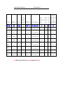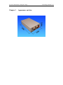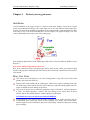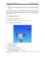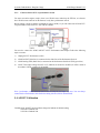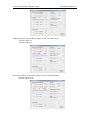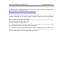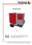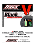
1
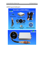
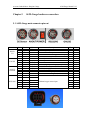
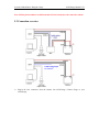
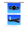
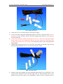
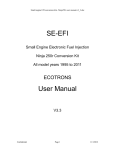
Accurate Lambda Meter- Daughter Gauge ALM-Gauge Manual V2.2 ALM-Gauge Accurate Lambda Meter __with a separate gauge Manual V2.2 ECTORONS LLC COPY RIGHT ECOTRONS LLC ALL RIGHT RESERVED www.ecotrons.com Copyright ECOTRONS LLC Page 1 of 20 Accurate Lambda Meter- Daughter Gauge ALM-Gauge Manual V2.2 Check before you power on ALM-Gauge: The oxygen sensor is installed in the right way; or if it's left in the free air, make sure it's dry and it's not close to the inflammable materials; The ALM-Gauge is correctly connected to DC power supply or 12V battery; Website: http://www.ecotrons.com Email: [email protected] www.ecotrons.com Copyright ECOTRONS LLC Page 2 of 20 Accurate Lambda Meter- Daughter Gauge ALM-Gauge included parts: ALM-Gauge Manual V2.2 Accurate Lambda Meter- Daughter Gauge ALM-Gauge Manual V2.2 Table of Content Chapter 1 ALM-Gauge Product Overview ............................................................................................. 5 Chapter 2 ALM-Gauge technical specifications ..................................................................................... 7 Chapter 3 Appearance and size ............................................................................................................... 9 Chapter 4 Protect your oxygen sensor .................................................................................................. 10 Chapter 5 ALM-Gauge hardware connection ........................................................................................11 5.1 ALM-Gauge main connector pin-out ...........................................................................................11 5.2 Connection overview .................................................................................................................. 12 5.3 Connection ALM to ECU............................................................................................................ 15 5.3.1 ALM connection via NB O2 connector ............................................................................... 15 5.3.2 Connect ALM to ECU via performance switch ................................................................... 16 5.4 ANOUT Calibration .................................................................................................................... 16 5.5 How to verify analog voltage matching lambda ......................................................................... 18 Chapter 6 DIGITAL AIR/FUEL RATIO MONITOR (Gauge) ............................................................. 19 6.1 Specification................................................................................................................................ 19 6.2 Application .................................................................................................................................. 19 Chapter 7 DTC table ............................................................................................................................. 20 Accurate Lambda Meter- Daughter Gauge Chapter 1 ALM-Gauge Manual V2.2 ALM-Gauge Product Overview ALM (Accurate Lambda Meter) is an air/fuel ratio (lambda) meter which uses Bosch LSU 4.9 wideband oxygen sensor and Bosch driver chip CJ125 to accurately measure the exhaust air/fuel ratio (AFR) of variant combustion engines. ALM-Gauge is a smaller size version of our previous ALM . It has the same accuracy and fast response characteristics like ALM, but much smaller size. The controller box has the size of 4"x2.6"x1", or similar to a business card size. It has a primary 0-5v linear analog output which can be used as the feedback control signal for an ECU. It also has an analog signal output to the 52mm digital LED gauge. The gauge is optional, because some professional tuners already have a lot of gauges which include AFR display as a part. ALM-Gauge uses more advanced LSU4.9 sensor instead of LSU4.2 which is still used by most other wideband controllers. LSU4.9 is the new generation wideband sensor evolving from LSU4.2. It is superior to LSU4.2 with the obvious proof: Bosch uses LSU4.9 across the board for their wideband applications. (See the appendix: LSU4.2 vs. LSU4.9 for a quick comparison) Here is why LSU4.9 is superior to LSU4.2: http://www.ecotrons.com/technology/bosch_lsu_49_is_superior_to_lsu_42_sensors/ ALM-Gauge can also use LSU4.9D sensor, but the need to update the software, if you need to use LSU4.9D, please explain in advance at the time of purchase ALM. Bosch chip CJ125 is the integrated chip (IC) specifically designed for LSU 4.9/4.2 Sensors. Bosch's own wideband controller, "LambdaTronic", uses CJ125 driver chip. In fact, Bosch uses this chip wherever a LSU sensor is used. The CJ125 and LSU sensor are mated-pair by Bosch. Presumably LSU sensors work the best with CJ125 chips. See here for Bosch Motorsport’s wideband controller, LT4: http://www.bosch-motorsport.de/media/catalog_resources/Function_Manual_LT4pdf.pdf Together, LSU 4.9 and CJ125 make our ALM a more accurate lambda meter in the automotive aftermarket. Besides air/fuel ratio measurement, ALM-Gauge provides some supplemental functions which make your measurement or tuning more convenient: linear analog output to your ECU; LED digital display; engine RPM probe, data logging with a serial communication to a PC, etc. List of ALM parts Small ALM controller 52mm digital LED gauge (optional) Harness (60in default, 120in optional) Bosch LSU 4.9 sensor Sensor plug and bung USB to serial converter (included) CD - documents and ALM GUI software Accurate Lambda Meter- Daughter Gauge Products ALM-Gauge Manual V2.2 O2 Sensor Channels supported ANOUT(Range) Communication Display RS232 AFR Gauge 1 YES(0 ~ 5v) LSU 4.9(default)/ADV NO NO YES YES SCI(0 ~ 5v) NO 1 YES(0 ~ 5v) LSU 4.9(default)/ADV NO NO NO NO CAN NO 1 NO LSU 4.9(default)/ADV NO NO NO NO ALM-B-RS485 RS485 NO 1 NO LSU 4.9(default)/ADV NO NO NO NO ALM-LED RS232 LED (4 bit) 1 YES(0 - 5v) LSU 4.9(default)/ADV NO NO YES YES ALM-CAN CAN NO 1 NO LSU 4.9(default)/ADV NO NO NO NO ALM-CAN-II CAN NO 2 NO LSU 4.9(default)/ADV NO NO NO NO ALM-II RS232 LCD(128*64) 2 YES(0 - 5v) LSU 4.9(default)/ADV NO NO YES YES ALM-LD RS232/CAN/USB LCD(640*480) 2 YES(0 - 10v) LSU 4.9(default)/ADV YES YES YES YES ALM-Gauge ALM-B-ANOUT ALM-B-CAN O2 Sensor Supported Virtual Exhaust Exhaust Engine narrow band o2 temperature pressure Speed sensor sensor sensor Input output(NBOUT) Note: Blue font represents the current user manual supported of ALM units. Accurate Lambda Meter- Daughter Gauge Chapter 2 ALM-Gauge Manual V2.2 ALM-Gauge technical specifications Power supply Input voltage range Input current Polarity protection Load Dump Clamp DC9V~15 V (12V Typical) 90mA typical plus the heater current Reverse polarity protected Maximum Voltage 33V Sensors Compatible Number of Sensors Free air calibration LSU4.9 (Support LSU4.9D, LSU 4.2 capable but not recommended) One No need (we measure the free air O2) Measurement Lambda range Lambda accuracy Air/Fuel Ratio λ = 0.5 ~ ∞(Gasoline AFR: 7.35 to free air) ±0.008 @ λ=1.00 ±0.01 @ λ=0.80 ±0.05 @ λ=1.70 Fuel dependent (see lambda range and accuracy) Control Current Heater return (H-) Built-in PID control with CJ125 Typical 1A; Max 1.5A Separate wire from Ground Heater Response time 5ms updating rate (everything finished in 5ms) Output Lambda analog output 0~5V user programmable Analog accuracy ±0.005V error with a 10-bit DAC chip Analog type Reference ground to ECU Second Lambda analog output 0~5V for a third party gauge, user programmable Narrow band O2 sensor simulated output Input RPM input Injection pick-up Communications Advanced CAN bus communications (optional) RS232 or USB (via a converter) for logging or programming User-friendly PC software for data acquisitions and analysis Display 52mm digital gauge with numbers in the censor and bar-graph LED around Main-Processor CPU Speed Memory Freescale MC9S12P128 16-bit micro-processor S12P (Auto industry rated) 32MHz 128k Flash, 6k RAM, 4k Data Special features On-Board-Diagnosis and error report Accurate Lambda Meter- Daughter Gauge Self-learning of part-to-part variations, aging effect Working with different types of fuels (gasoline, diesel, E85, etc.) General ALM-Gauge Manual V2.2 Temperature range Dimensions -40oC ~ 125oC 4.0" x 2.6" x 1.0" Accurate Lambda Meter- Daughter Gauge Chapter 3 Appearance and size ALM-Gauge Manual V2.2 Accurate Lambda Meter- Daughter Gauge Chapter 4 ALM-Gauge Manual V2.2 Protect your oxygen sensor Installation Correct installation of the oxygen sensors is a must to avoid sensor damage. It protects the oxygen sensor from condensations and gives the sensor longer life. It also can make the measurement more accurate. The sensor body should be perpendicular to the exhaust gas flow, and it should also be tilted in the range of 10o~75o from the horizontal line (see below figure). The typical tilt-angle is 30o. The sensor head should be close to the center of the exhaust pipe. After finding the right location on the exhaust pipe, drill a hole of 18 mm in diameter. Weld the sensor bung on it. Note: do not weld the bung with the sensor in it. Note, if you vehicle has a Bosch switching oxygen sensor (LSF) on your vehicle, you can just un-plug the LSF, and plug-in the wideband LSU sensor into the hole. Bosch LSU and LSF have the same size of the thread. More User Notes LSU sensors are not designed to work with leaded gasoline. Using LSU sensor with leaded gasoline will reduce the sensor life. With the LSU sensor installed in the exhaust pipe, whenever the engine is running, please also run ALM-Gauge, which controls the LSU heater. Otherwise, long-time-running engine with LSU sensor not heated can cause damage of the sensor. LSU sensor is preferred to run within the temperature range of 500~900oC, the best temperature is 780oC. Too high temperature (>1030oC) will cause damage of the sensor. Refer to Bosch LSU4.9 data for more details about the variant temperature requirements. www.bosch-motorsport.de/pdf/sensors/lambda/LSU49.pdf Avoid heating the LSU sensor before the engine is running. At the engine start, there may be condensations in the exhaust gas, which can cause damage of the sensor. The preferred order: start the engine first, then immediately turn on the ALM-Gauge, which will ramp up the heating power smoothly. Accurate Lambda Meter- Daughter Gauge Chapter 5 ALM-Gauge Manual V2.2 ALM-Gauge hardware connection 5.1 ALM-Gauge main connector pin-out Connector RS232/ I/O GAUGE ANOUT/ POWER O2 Sensor Pin# 1 2 3 4 5 1 2 3 4 1 2 3 4 5 1 2 3 4 5 6 Wire# Gray Purple yellow Green Black Yellow Red Black Green Black Red Black Blue Black Red Yellow White Grey Green Black Name TXD RPM RXD NO2OUT GND-R +12V +12V GND-R GAUGE GND-R +12V GND-R ANOUT GND-H IP VM HH+ IA UN Description Serial communication port Injection signal input Serial communication port Simulated narrow band oxygen sensor output Ground (Reference ground) +12V Output +12V Output Ground coarse analog output to the gauge (optional) Ground (Reference ground) +12V Power supply Ground (Reference ground) Lambda linear analog output (fine) Ground (Heater circuit ground) wideband oxygen sensor input Min -15V 0V -15V 0V 0V 12V 12V 0V 0V 0V 9V 0V 0V 0V — — — — — — Max 15V 12V 15V 1V 0V 12V 12V 0V 1V 0V 15V 0V 5V 0V — — — — — — Accurate Lambda Meter- Daughter Gauge ALM-Gauge Manual V2.2 Note: LSU4.9 pin-out numbers are different than LSU4.2, but they have the same color scheme. 5.2 Connection overview 1) Plug-in the four connectors from the harness into ALM-Gauge, Connect Gauge to your ALM-Gauge. Accurate Lambda Meter- Daughter Gauge ALM-Gauge Manual V2.2 Gauge 2) Connect the 6-pin LSU4.9 mating connector to the O2 sensor. Connector to the O2 sensor 3) Connect the 12V+ to 12V battery plus or the DC power supply +; Accurate Lambda Meter- Daughter Gauge ALM-Gauge Manual V2.2 Power supply and ANOUT 4) Connect the 12V- to 12V battery minus or the DC power supply- ; 5) If you do not want to output the lambda analog signal to your ECU, connect the GND (reference ground, pin4) to the 12V battery minus or DC power supply ground; otherwise, refer to step 4.5 for GND connection. 6) If you want to output the lambda analog signal to your ECU, connect the ALM-Gauge lambda analog output to your ECU analog input, and then you must connect the ALM-Gauge GND (reference ground, pin4) to the ECU analog GND (most likely your ECU has a sensor ground for analog inputs). 7) Optional: Splice the injector-driver wire on the ECU side (usually low-side-driver type), and tap the ALM-Gauge RPM input wire to it. Use the electrical tape to wrap it. RPM, COM and NBOUT 8) Optional: connect the switching O2 sensor simulated output (NBOUT) to the OEM ECU. This can prevent the OEM ECU turn on the MIL light. Note, the OEM switching sensor can be different from each other, and it's your responsibility to figure out how to connect the wires Accurate Lambda Meter- Daughter Gauge ALM-Gauge Manual V2.2 correctly. 9) Optional: connect ALM-Gauge to your laptop / PC via the serial communication cable (DB9 connector). If you computer does not have a serial port, you need an extra USB-RS232converter. 10) Users can set the ANOUT output AFR or Lambda. We will set it in our factory according to the uses’ requirement. The standard ANOUT output is AFR. If users want it to output lambda or O2%, users can modify it by using ALM GUI. Connected ALM-Board to computer, click SettingsALM Parameters, open ALM Parameters window. You can select what you want to modify the ANOUT output and Burn to ALM. 5.3 Connection ALM to ECU There are 2 ways to connect ALM to (Ecotrons) ECU: Connected via NB O2 connector Connected via performance switch. We recommend the first connection. 5.3.1 ALM connection via NB O2 connector From left to right in the picture: Heater circuit - (Blue-Yellow) Heater circuit + (Blue) Reference Ground (Green) O2in - O2 sensor input (Gray-Black #8) Our ALM-Gauge harness comes with 2 wires: ANOUT (Blue) - analog output representing the lambda GND (Black) - reference ground You need to connect the ANOUT (Blue) to O2in (Gray-Black #8) and GND (Black) to Ground (Green). Accurate Lambda Meter- Daughter Gauge 5.3.2 ALM-Gauge Manual V2.2 Connect ALM to ECU via performance switch For some two-stroke engines, maybe, there is no NB O2 sensor when buy the EFI kits, so it doesn’t have NB O2 sensor connector on the harness, it only has a performance switch. But for tuning, it needs to install a wideband O2 sensor (ALM), so you can connect the ALM to ECU via performance switch, then ECU can read the Lambda. You need to connect the ALM'S ANOUT to ECU Performance-Switch input. Follow the following steps to connect: 1) Unplug the ECU Performance switch 2) ALM'S ANOUT (blue line) is connected to the white line of the Performance-Switch 3) ALM'S analog GND (black line) is connected to the Performance-Switch of GND (green line) 4) ANOUT the output voltage from 0V to 5V, and does not need to be modified; it will be varied in accordance with the variation of the lambda. Note: "performance switch" then can not be used to swap the fuel maps any more. You can always connect back to Performance Switch after the tuning is done (ALM is disconnected). 5.4 ANOUT Calibration Lambda mode, ANOUT used to indicate changes in lambda, the default setting: 0.00 Volt at Lambda 0.50 5.00 Volt at Lambda 2.00 Accurate Lambda Meter- Daughter Gauge AFR mode, ANOUT used to indicate changes in AFR, the default setting: 0.00 Volt at AFR 7.35 5.00 Volt at AFR 29.4 O2% mode, ANOUT used to indicate changes in O2%, the default setting: 0.00 Volt at O2% -20.99 5.00 Volt at O2% 20.99 ALM-Gauge Manual V2.2 Accurate Lambda Meter- Daughter Gauge ALM-Gauge Manual V2.2 If customers want to modify these parameters, customers can refer to ALM GUI Manual 2.4 ALM GUI using COM or USB communication. http://www.ecotrons.com/files/ALM%20GUI%20Manual.pdf Note:The limit range of analog voltage is 0-5v. The value of lambda is 0.5-16. The low voltage must match the low Lambda. You can’t make 5V match 0.5 Lambda. AFR and O2% are same with Lambda. How to verify analog voltage matching lambda Since you have 2 ALMs, the way to compare is easy. You can either cross check 2 ALMs with the same sensor, or check 2 sensors, with 1 ALM. And the next step to check good lambda: 1) Put the sensor in the free air, and use ALM GUI , to read the O2%;if it is close to 20% ;the ALM and sensor is good, otherwise, you could do Free air calibration. 2) If ALM GUI gives good O2%, then measure the ANOUT analog voltage, with a voltage meter, convert that voltage back to lambda, and compare it against the lambda in the ALM GUI. This is to verify the analog voltage is really matching the lambda measured. Accurate Lambda Meter- Daughter Gauge Chapter 6 ALM-Gauge Manual V2.2 DIGITAL AIR/FUEL RATIO MONITOR (Gauge) 6.1 Specification 1. Input Voltage: 0 ~ 1v 2. Display Range: digital type is from 20.0% to 10.0%; analog LED type is from 20.0% to 10.0%; both of digital type and analog LED type will show the maximum or the minimum, if the value out off the display range. 3. Accurately of digital type: Every 0.1%. 4. Accurately of analog LED type: Every 0.5%, using BAR type to light up. 6.2 Application 1. General Display: The digital display will show the percentage, and value is corresponding with analog LED. 2. Electrics voltage display & warning function: A. When at the start, Red LED (for VOLT only) will light up and digital display will show the value of voltage at 30 seconds. After then, the digital display will show the value of AIR/FUEL. Every 10 minutes show the voltage at 30 seconds. B. When the voltage is lower than 11.0v, Red LED (for VOLT only) will shine and the digital display will show the value and keeping shine to warning. C. When the value of AIR/FUEL is lower than 10AFR or higher than 20AFR over 3 seconds, the digital display will keeping shine to warning. Accurate Lambda Meter- Daughter Gauge Chapter 7 ALM-Gauge Manual V2.2 DTC table Below is the Diagnostic Trouble Code table. ALM-Gauge has on-board-diagnostics capability to detect most common errors. The first thing user should do when ALM-Gauge is not working appropriately is to read DTCs. Trouble Code E1 Internal communication error Contact the manufacturer E2 Internal register error Contact the manufacturer E3 LSU yellow wire (VM) short to power Description Solutions 1. Check the harness for short-to-power 2. Change the LSU E4 LSU yellow wire (VM) short to GND 1. Check the harness for short-to-ground 2. Change the LSU E5 LSU black wire (UN) short to power 1. Check the harness for short-to-power 2. Change the LSU E6 LSU black wire (UN) short to GND 1. Check the harness for short-to-ground 2. Change the LSU E7 LSU green wire (IA) short to power 1. Check the harness for short-to-power 2. Change the LSU E8 LSU green wire (IA) short to GND 1. Check the harness for short-to-ground 2. Change the LSU E9 Operating voltage too low Check the power supply to the ALM spec. E10 Heater circuit damaged Contact the manufacturer E11 Heater circuit short to power Contact the manufacturer E12 Heater circuit short to GND 1. Check the harness for short-to-ground 2. change LSU 3. Contact the manufacturer