1
Order this document
by AN1836/D
Freescale Semiconductor
Freescale Semiconductor, Inc...
AN1836
FLASH Programming for Motorola MC68HC912
Microcontrollers
By Matt Ruff
Body Electronics and Occupant Safety Systems Engineering
Austin, Texas
Introduction
This document outlines basic routines that demonstrate how to program
and erase FLASH EEPROM on the MC68HC912 Family of
microcontrollers (MCU) through the background debug mode (BDM)
interface using a Freescale serial debug interface (SDIL) and the
SDBUG12 software (version 2.15) from P&E Microcomputer Systems,
Inc. SDBUG12 is a software interface tool to the SDIL hardware, which
allows for background monitoring of the M68HC12 Family of MCUs.
Information pertaining to the proper conditioning and handling of the
external voltage supply used to program the FLASH EEPROM
(electrically erasable programmable read-only memory) also is included.
Care must be taken to ensure proper programming and to prevent
damage to the device or data corruption in the memory array.
This application note provides updated information to the engineering
bulletin titled Erasing and Programming the FLASH EEPROM on the
MC68HC912B32, Freescale document order number EB183/D, in
addition to a much greater detailed description of the programming
voltage supply considerations needed to design an application.
© Freescale Semiconductor, Inc., 2004. All rights reserved.
© Motorola, Inc., 2000
AN1836
For More Information On This Product,
Go to: www.freescale.com
Freescale Semiconductor, Inc.
Application Note
Freescale Semiconductor, Inc...
The 32 Kbytes of embedded FLASH EEPROM are a primary reason why
the MC68HC912B32 device is so useful. This module serves as
electrically programmable and erasable, non-volatile ROM-like memory,
allowing for storage of program code which:
•
Must be executed frequently
•
Must be executed at high speeds
•
Might need to be upgraded in the field later
The programming routines and registers referred to in this document
pertain to the MC68HC912B32 device. However, the concepts covered
here hold for the entire MC68HC912 FLASH MCU Family and any other
Freescale microcontrollers which share this same FLASH technology
(also called 1.5T FLASH EEPROM or UDR FLASH technology).
Included in this list are the M68HC16 and 683xx Families. Some of the
newest M68HC12 Family devices are moving to a new FLASH
technology and contain an A at the end of the part number to
differentiate the FLASH technology used (for instance,
MC68HC912D60A).
FLASH EEPROM Control Block
The FLASH EEPROM is controlled by a 4-byte register block, which is
located at address $00F4 upon reset. Within this block are four singlebyte registers:
•
Lock control register, FEELCK
•
Module configuration register, FEEMCR
•
Module test register, FEETST
•
Module control register, FEECTL
For more detail on these control registers, refer to Section 8.4 FLASH
EEPROM Registers in the MC68HC912B32 / MC68HC912BE32
Advance Information, Freescale document order number
MC68HC912B32/D. This section can be found in the appropriate
documents for all M68HC12 Family MCUs. The sequence of how to use
these registers is covered later in this document.
AN1836
2
For More Information On This Product,
Go to: www.freescale.com
Freescale Semiconductor, Inc.
Application Note
FLASH EEPROM Control Block
FLASH EEPROM
Lock Control
Register
The FEELCK register (located at $00F4) contains only the LOCK bit
(bit 0), which allows or prevents writing to the FEEMCR register. This
must be cleared to change the FEEMCR. Note that it is cleared out of
reset.
Address:
Read:
Freescale Semiconductor, Inc...
Write:
Reset:
$00F4
Bit 7
6
5
4
3
2
1
Bit 0
0
0
0
0
0
0
0
LOCK
0
0
0
0
0
0
0
0
Figure 1. FLASH EEPROM Lock Control Register (FEELCK)
FLASH EEPROM
Module
Configuration
Register
The FEEMCR register (located at $00F5) contains only the BOOTP bit
(bit 0), which protects the 2-Kbyte boot block (1 Kbyte in early mask sets
G86W or G75R) located at $7800–$7FFF. This bit must be cleared, after
the FEELCK (LOCK bit) is cleared, to write or erase the boot block.
Address:
Read:
Write:
Reset:
$00F5
Bit 7
6
5
4
3
2
1
Bit 0
0
0
0
0
0
0
0
BOOTP
0
0
0
0
0
0
0
1
Figure 2. FLASH EEPROM Module Configuration Register
(FEEMCR)
FLASH EEPROM
Module Test
Register
The FEETST register (located at $00F6) has no effect and always reads
0 in normal modes of operation.
Address:
Read:
Write:
Reset:
$00F6
Bit 7
6
5
4
3
2
1
Bit 0
0
0
0
0
0
0
0
0
0
0
0
0
0
0
0
0
Figure 3. FLASH EEPROM Module Test Register (FEETST)
AN1836
3
For More Information On This Product,
Go to: www.freescale.com
Freescale Semiconductor, Inc.
Application Note
FLASH EEPROM
Control Register
The FEECTL register (located at $00F7) controls the actual
programming and erasing of the FLASH EEPROM. In this register, five
bits are used to control the FLASH. All bits are 0 upon reset.
Address:
$00F7
Read:
Write:
Freescale Semiconductor, Inc...
Reset:
Bit 7
6
5
4
3
2
1
Bit 0
0
0
0
FEESWAI
SVFP
ERAS
LAT
ENPE
0
0
0
0
0
0
0
0
Figure 4. FLASH EEPROM Control Register (FEECTL)
FEESWAI
FEESWAI (bit 4) controls the behavior of the FLASH EEPROM clock
while in wait mode.
SVFP
SVFP (bit 3), the VFP status bit, is set when VFP is near normal
programming voltage levels; clear otherwise (read only). This is not a
guarantee that VFP is within specified tolerances and should be used
only as a secondary check.
ERAS
ERAS (bit 2), when set, configures the array for erasure.
LAT
LAT (bit 1), when set, enables the programming latches.
ENPE
ENPE (bit 0), when set, applies the programming/erase voltage to the
array.
AN1836
4
For More Information On This Product,
Go to: www.freescale.com
Freescale Semiconductor, Inc.
Application Note
Hardware Configuration
Hardware Configuration
Freescale Semiconductor, Inc...
Setting Up
the Debugging
Hardware
Since programming the FLASH EEPROM takes a finite amount of time
and is dependent on a reliable programming voltage from an exterior
source, it is difficult to tell if the procedure worked immediately. Also, it
should be verified by some sort of external signal. To simplify the
debugging of the process, try using a few hardware techniques that are
listed in this application note.
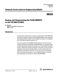
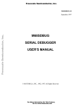
For debugging hardware, simply use light-emitting diodes (LED),
connected to port pins on the MC68HC912B32 device to use as error
and sequence successfully complete indicators. For use with the code
listed here, connect a red LED to PA0, with a 1-kΩ current limiting
resistor to indicate errors. In like manner, connect a green LED to PA1
to indicate that the process has completed successfully. Refer to
Figure 5 for connections.
GREEN (OK)
MC68HC912B32
1 kΩ
PA1
RED (ERROR)
1 kΩ
PA0
Figure 5. Debugging Hardware Connections
Setting Up the
M68HC12B32EVB
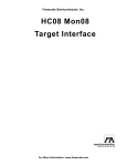
Be sure to connect the programming voltage (VFP) source to W8 on the
M68HC12B32EVB with the proper polarity. W8 allows VFP to be
connected to the board, but the jumper on W7 actually transfers VFP to
the VFP pin (pin 69) on the microcontroller. The default location of W7
applies VDD to the VFP pin, and a jumper should always be located here
to maintain the voltage on the VFP pin when programming and erasing
are not occurring. See Figure 6 for the locations of W7 and W8.
Refer to the Evaluation Board User’s Manual, which comes with the
M68HC12 evaluation board, Freescale part order number
M68EVB912B32, for detailed connection information.
AN1836
5
For More Information On This Product,
Go to: www.freescale.com
Freescale Semiconductor, Inc.
Application Note
W7 JUMPER TO APPLY
VFP TO PIN.
Freescale Semiconductor, Inc...
VFP
Figure 6. M68EVB912B32 Evaluation Board Connections
The M68HC12B32EVB is designed to be used for evaluation purposes
only and does not have sufficient protection against improper VFP
voltage levels for a production level system. Refer to Example VFP
Protection Circuitry in this document for more detailed circuit
information for proper circuit design and protection of the VFP pin and
FLASH EEPROM in the MCU.
NOTE:
VFP should be 11.4–11.8 volts for mask sets 1H91F and 3H91F. For all
other masks, use 11.4–12.6 volts (12 volts ±5%).
Software Considerations
Using SDBUG12 to manipulate the FLASH EEPROM requires some
special considerations. First, a few bugs in some versions of the
software can cause confusion when manipulating the FLASH memory
array. The memory display windows sometimes do not refresh properly,
sometimes showing all of the odd addresses as one value and all the
even addresses as another value. To fix this problem, issue a RESET
command from the SDBUG12 command prompt to force SDBUG12 to
refresh all of its display windows from the MCU once the part comes out
of reset.
AN1836
6
For More Information On This Product,
Go to: www.freescale.com
Freescale Semiconductor, Inc.
Freescale Semiconductor, Inc...
Application Note
Software Considerations
The routines that follow were tested with version 2.15 of SDBUG12
running on a Windows NT workstation in a DOS window. The problem
described in the preceding paragraph did not appear when executing
these routines. SDBUG12 displayed the proper values for the FLASH
array when the routines were allowed to run to completion. Both of the
code segments included here can be loaded into the RAM of the part at
the same time since they do not overlap. Use the LOAD command in
SDBUG12 to load each segment into RAM. Notice that the entry point of
the program routine is $80A and the entry point of the erase routine is
$90A. Once loaded into RAM, the command G 80A will begin the
programming process or G 90A will begin the erase process.
For a detailed description of the software commands for SDBUG12,
refer to documentation from P&E Microcomputer Systems, Inc.
NOTE:
Once the FLASH array has been erased or programmed, reloading the
DBUG12 monitor code into the FLASH array is necessary if that monitor
is to be used, as manipulation of the array will have destroyed this code.
This can be accomplished with the bootloader in the boot block of the
part or by using a software programming tool, such as Prog12s, which is
a product of P&E Microcomputer Systems, Inc.
If using the M68EVB912B32 evaluation board, refer to the Evaluation
Board User’s Manual, which comes with the evaluation board, for further
information on how to reload the monitor program into the device using
the on-board bootloader.
General Notes
on Coding FLASH
Programming
and Erasing
The routines used in this application note are designed for reference
purposes. Programming and erase routines always should be
downloaded to the device at the time of programming through the BDM
or through a CAN, J1850, or other communication link. The code for
these algorithms should not be resident on the device during normal
operations.
One reason for not including these routines in FLASH or EEPROM is to
prevent possible activation in a code runaway situation. If the code gets
Windows NT is a registered trademark of Microsoft in the U.S. and other countries.
AN1836
7
For More Information On This Product,
Go to: www.freescale.com
Freescale Semiconductor, Inc.
Application Note
"lost," it is possible that the programming voltage could be applied to the
array for a time much longer than the specifications allow, resulting in
corruption of data. Obviously, implementing FLASH-modifying code,
such as bootloaders stored in FLASH, could result in such a case if the
microcontroller were to get lost and start executing code at a random
point.
Freescale Semiconductor, Inc...
NOTE:
In cases such as this, great care must be taken to test all of the code to
make certain that FLASH modification routines cannot be activated
accidentally.
If these routines must be located in non-volatile memory (NVM), other
ways to safeguard against code runaway are possible. For instance, if
assembly opcodes are interlaced with software interrupt (SWI)
instructions, splitting up the instruction which modifies the FEECTL
register to apply the programming voltage to the array prevents
accidental modification of that register. To actually run the code, that
section of code in RAM would need to be reconstructed by copying the
bytes from their interlaced location in NVM using a message from the
CAN, J1850, SCI, etc., which contains the decryption key for the
locations of the scrambled opcodes. The SWI instructions are not
essential, but would ensure that the device would execute an SWI if the
code were lost in this region, alerting the engineer to a possible
dangerous condition. This concept is complicated and is beyond the
scope of this application note. It is mentioned here only to offer one
possible alternative to avoid accidental activation of program or erase
routines.
The other major reason to simply leave the program and erase routines
out of the NVM is in the interest of software reuse. As newer devices are
developed and newer FLASH technologies emerge, the algorithms for
programming and erasing these routines also are being refined. If the
algorithms themselves are downloaded dynamically to the target
devices at the time of programming, the newest algorithms can be
utilized with little impact to the target system. This allows the target
system software to remain FLASH technology independent, minimizing
engineering time required for code development and testing.
AN1836
8
For More Information On This Product,
Go to: www.freescale.com
Freescale Semiconductor, Inc.
Application Note
Programming the FLASH Array
Programming the FLASH Array
Programming the FLASH EEPROM is accomplished by this step-bystep procedure. The VFP pin voltage must be at the proper level prior to
executing step 4 the first time.
1. Apply program/erase voltage to the VFP pin.
Freescale Semiconductor, Inc...
2. Clear ERAS and set the LAT bit in the FEECTL register to
establish program mode and enable programming address and
data latches.
3. Write data to a valid address. The address and data are latched.
If BOOTP is asserted, an attempt to program an address in the
boot block will be ignored.
4. Apply programming voltage by setting ENPE.
5. Delay for one programming pulse, tPPULSE.
6. Remove programming voltage by clearing ENPE.
7. Delay while high voltage is turning off, tVPROG.
8. Read the address location to verify that it has been programmed.
9. If the location is not programmed, repeat steps 4 through 7 until
the location is programmed or until the specified maximum
number of program pulses, nPP, has been reached.
10. If the location is programmed, repeat the same number of pulses
as required to program the location. This provides 100 percent
program margin.
11. Read the address location to verify that it remains programmed.
12. Clear LAT.
13. If there are more locations to program, repeat steps 2 through 10.
14. Turn off VFP. Reduce voltage on VFP pin to VDD.
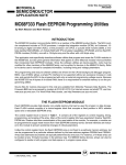
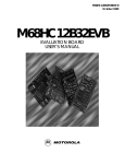
The flowchart in Figure 7 demonstrates the recommended
programming sequence.
AN1836
9
For More Information On This Product,
Go to: www.freescale.com
Freescale Semiconductor, Inc.
Application Note
START PROG
TURN ON VFP
CLEAR MARGIN FLAG
CLEAR PROGRAM PULSE COUNTER (nPP)
CLEAR ERAS
SET LAT
Freescale Semiconductor, Inc...
WRITE DATA
TO ADDRESS
SET ENPE
DELAY FOR DURATION
OF PROGRAM PULSE
(tPPULSE)
CLEAR ENPE
SET
MARGIN FLAG
DELAY BEFORE VERIFY
(tVPROG)
IS
MARGIN FLAG
SET?
INCREMENT
nPP COUNTER
READ
LOCATION
NO
YES
DECREMENT
nPP COUNTER
DATA
CORRECT?
YES
NO
NO
nPP = 0?
nPP = 50?
YES
DATA
CORRECT?
NO
YES
NO
YES
CLEAR LAT
GET NEXT
ADDRESS/DATA
NO
LOCATION FAILED
TO PROGRAM
DONE?
YES
TURN OFF VFP
DONE PROG
Figure 7. Programming Sequence Flowchart
AN1836
10
For More Information On This Product,
Go to: www.freescale.com
Freescale Semiconductor, Inc.
Freescale Semiconductor, Inc...
Application Note
Programming the FLASH Array
The following code segment adheres to the recommended procedure for
programming the FLASH array. The flowchart in Figure 7 outlines this
same procedure. The general idea is to set the programming latches,
write the desired byte/word to the location in the array, apply the
programming voltage to the FLASH module within the chip (by setting
the ENPE bit), then to make sure the location is programmed properly.
If the data is correct, then the number of times the programming voltage
was applied to get this byte programmed will have been preserved in the
NPP variable. The programming voltage is then pulsed that many times
again to ensure that the byte/word remains programmed. This is a 100
percent programming margin. This whole process is repeated for each
byte/word to be programmed. The next code segment simply copies a
string of characters from RAM and stores it at the beginning of the
FLASH array.
The source code for this application note is available on Motorola’s Web
site at http://www.freescale.com.
NOTE:
In the following code, the STEP comments refer to the steps shown at
the beginning of this section. Some steps in the code do not correspond
directly to the programming algorithm, but are included simply to provide
output to the indicator LEDs to show the user the status of the program.
;----------------------------------------------------;--Application Note Source Code for AN1836
--;--Erasing and Programming the FLASH --;--EEPROM on the MC68HC912B32
--;----;--- FLASH EEPROM program routine
--;--- MC68HC912B32 1.5T FLASH Module
--;----;--- Rev. 1.2 February 9, 2000
--;--Created Bit Name Labels for easier reading--;--Streamlined Code for efficiency
--;--- Rev. 1.0 - April 23,1998
--;--Fixed Tppulse = 25us and Tvprog = 10us
--;--- Written November 6, 1997
--;----;--ASSEMBLER:
IASM12 v. 3.06
--;--P & E Microcomputer Systems--;----;--- by Matt Ruff, BE/OS Systems Engineering
--;----;--- This code is intended for instructional use --;--- only. Freescale assumes no liability for use --;--- or modification of this code. It is the
--;--- responsibility of the user to verify all
--;--- parameters, variables, timings, etc.
--;-----
AN1836
11
For More Information On This Product,
Go to: www.freescale.com
Freescale Semiconductor, Inc.
Application Note
;-------------------------------------------------------$BASE
10T
;Set assembler default base to base 10
Freescale Semiconductor, Inc...
;-----------------------------Equates
FEEStart:
EQU
$8000
FEEEnd:
EQU
$FFFF
FEESize:
EQU
$8000
FEEWords:
EQU
{FEESize/2}
MaxNpp:
EQU
50
---------------------------------;FLASH Start address
;FLASH End address
;Num of words is number of bytes divided by two
;50 pulses maximum
FEELCK:
FEEMCR:
FEECTL:
LOCK:
BOOTP:
SVFP:
ERAS:
LAT:
ENPE:
EQU
EQU
EQU
EQU
EQU
EQU
EQU
EQU
EQU
$F4
$F5
$F7
$01
$01
$08
$04
$02
$01
;FLASH Lock Control Register
;FLASH Module Configuration Register
;FLASH Control Register
;Lock register Bit in FEELCK
;Boot Protect Bit in FEEMCR
;Status Vfp Voltage Bit in FEECTL
;Erase Control Bit in FEECTL
;Programming Latch Control bit in FEECTL
;Enable Program/Erase Voltage Bit in FEECTL
PORTA:
DDRA:
PA0on:
PA1on:
EQU
EQU
EQU
EQU
$0000
$0002
$01
$02
;Port A data register
;Port A data direction register
Mult:
EQU
1000
EClock:
EQU
{Mult*8000}
;Multiplier for EClock, assembler won't do
; values over 2^16
;E-clock frequency in Hz.
mS1LoopTime:
mS1Delay:
EQU
EQU
Npp:
MarginFlag:
DS
DS
4
;Num of clock cycles per loop.
{EClock/(mS1LoopTime*1000)};Must surround expression w/{()}
; for P&E.
;Factor of 1000 used for base time of 1 ms.
;----------------------------Equates
----------------------------ORG
1
1
$0800
ORG
$80A
LDS
BRCLR
LDX
#$B00
;(Turn on your Vfp power supply to board)
FEECTL,$08,Error;If Vfp not present, output an error
#$0000
CLR
CLR
Npp
MarginFlag
;Clear number of pulses
;Clear MarginFlag
MOVB
LDAB
#LAT,FEECTL
DATA,X
;Set LAT in FEECTL
STAB
FEEStart,X
;Write data to address
;Number of programming pulses applied
;Programming margin flag
Start:
Loop:
;- Step 2 -
;- Step 3 ;- Step 4 STEP4:
AN1836
12
For More Information On This Product,
Go to: www.freescale.com
Freescale Semiconductor, Inc.
Application Note
Programming the FLASH Array
BSET
FEECTL,ENPE
;Apply programming voltage (Set ENPE)
JSR
dly_22us
;Delay time for prog pulse (Tppulse)
BCLR
FEECTL,ENPE
;Remove programming voltage (Clear ENPE)
JSR
TST
BEQ
dly_10us
MarginFlag
NoFlag
;Delay for high voltage turn off (Tvprog)
;Is MarginFlag set??
;If not, go bump counter and check data
DEC
TST
BNE
Npp
Npp
STEP4
;Decrement Npp
;Is Npp=0?
;If not, go to Step 4
LDAA
CMPA
BNE
FEEStart,X
DATA,X
Error
;Read FEEPROM location to verify programming
;Is it the same as the byte to be programmed?
;Programming failed, output an error
BCLR
INX
CMPA
BNE
BRA
FEECTL,LAT
;Clear LAT in FEECTL
#$00
Loop
Done
;Check for $00 delimiter character
;If not, go back to start!
;If so, quit.
INC
LDAA
CMPA
BEQ
LDAB
CMPB
BLS
BSR
Npp
FEEStart,X
DATA,X
SetMarginFlag
Npp
#MAXNpp
STEP4
Error
;Increment number of prog pulses applied
;Read FEEPROM location to verify programming
;Is it the same as the byte to be programmed?
;If so, set the margin flag
INC
BRA
MarginFlag
STEP4
;Set MarginFlag
CLR
MOVB
MOVB
BRA
PORTA
#$FF,DDRA
#PA1on,PORTA
*
;Clear Port A
;Set DDRA to outputs
;Turn on PA1 to indicate complete
;(Turn off Vfp supply - programming complete)
;- Step 5 ;- Step 6 ;- Step 7 -
YesFlag:
Freescale Semiconductor, Inc...
;- Step 9 -
;- Step 10 -
NoFlag:
;Have we applied max number of pulses?
;If not, continue programming
;If so, we have a problem
SetMarginFlag:
Done:
;----------------------------------------------------------------------;----------------------Error Subroutine
---------------------;----------------------------------------------------------------------Error:
CLR
PORTA
;Clear Port A
MOVB
#$FF,DDRA
;Set DDRA to outputs
Blink:
MOVB
#PA0on,PORTA ;Turn PA0 on for error output
BSR
dly_500ms
;Delay so blinking is visible (1/2 second between
; flashes)
MOVB
#$00,PORTA
;Turn PA0 off
BSR
dly_500ms
BRA
Blink
;Repeat ad nauseam....
AN1836
13
For More Information On This Product,
Go to: www.freescale.com
Freescale Semiconductor, Inc.
Application Note
Freescale Semiconductor, Inc...
;----------------------------------------------------------------------;---------------------Delay Subroutines
----------------------;----------------------------------------------------------------------dly_500ms:
LDD
#500
;Delay for 500 ms
BSR
DelaymS
RTS
;----------------------------------------------------------------------;--Millisecond Delay Routine
--;----;--Call with the number of ms to delay in the D accumulator.
--;--The delay is not exact, but close enough when delaying ms.
--;----------------------------------------------------------------------DelaymS:
DlyLoop1mS:
LDX
#mS1Delay
;Load 1ms delay count into X
DlyLoop:
NOP
;Decrement count
DBNE
X,DlyLoop
;Loop until done.
DBNE
D,DlyLoop1mS
RTS
;----------------------------------------------------------------------;--Microsecond Delay Routines
(8MHz e clock)
--;----;--- To reduce loop overhead, the following routines have been
--;--- optimized by counting cycle time and calculating the delay
--;--- based on an 8MHz system clock.
--;----------------------------------------------------------------------dly_22us:
LDD
#52
DBNE
RTS
D,d_22u
;
;
;
;
;
Delay for about 22-23us
JSR or BSR is 4 cycles
Total delay is {4+2+(loopcount*3)+5}*125ns
For a loopcount of 52 yields 20.875us
-2 cycles-
d_22u:
dly_10us:
LDD
#24
DBNE
RTS
D,d_10u
; -3 cycles; -5 cycles;
;
;
;
;
Delay for about 10us
JSR or BSR is 4 cycles
Total delay is {4+2+(loopcount*3)+5}*125ns
For a loopcount of 24 yields 10.375us
-2 cycles-
d_10u:
DATA
FCB
FCB
; -3 cycles; -5 cycles-
"Freescale Microcontrollers"
$00
END
AN1836
14
For More Information On This Product,
Go to: www.freescale.com
Freescale Semiconductor, Inc.
Application Note
Erasing the FLASH Array
Erasing the FLASH Array
This sequence demonstrates the recommended procedure for erasing
the FLASH EEPROM. The VFP pin voltage must be at the proper level
prior to executing step 4 the first time.
1. Turn on VFP. Apply program/erase voltage to the VFP pin.
Freescale Semiconductor, Inc...
2. Set the LAT bit and ERAS bit to configure the FLASH EEPROM
for erasing.
3. Write to any valid address in the FLASH array. This allows the
erase voltage to be turned on; the data written and the address
written are not important. The boot block will be erased only if the
control bit BOOTP is negated.
4. Apply erase voltage by setting ENPE.
5. Delay for a single erase pulse, tEPULSE.
6. Remove erase voltage by clearing ENPE.
7. Delay while high voltage is turning off, tVERASE.
8. Read the entire array to ensure that the FLASH EEPROM is
erased.
9. If all of the FLASH EEPROM locations are not erased, repeat
steps 4 through 7 until either the remaining locations are erased
or until the maximum erase pulses have been applied, nEP.
10. If all of the FLASH EEPROM locations are erased, repeat the
same number of pulses as required to erase the array. This
provides 100 percent erase margin.
11. Read the entire array to ensure that the FLASH EEPROM is
erased.
12. Clear LAT.
13. Turn off VFP. Reduce voltage on VFP pin to VDD.
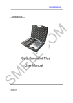
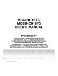
The flowchart in Figure 8 demonstrates the recommended erase
sequence.
AN1836
15
For More Information On This Product,
Go to: www.freescale.com
Freescale Semiconductor, Inc.
Application Note
START ERASE
TURN ON VFP
CLEAR MARGIN FLAG
CLEAR ERASE PULSE COUNTER (nEP)
SET ERAS
SET LAT
Freescale Semiconductor, Inc...
WRITE TO ARRAY
SET ENPE
DELAY FOR DURATION
OF ERASE PULSE
(tEPULSE)
CLEAR ENPE
SET
MARGIN FLAG
DELAY BEFORE VERIFY
(tVERASE)
IS
MARGIN FLAG
SET?
NO
INCREMENT
nEP COUNTER
READ
ARRAY
YES
DECREMENT
nEP COUNTER
ARRAY
ERASED?
YES
NO
NO
nEP = 0?
nEP = 5?
YES
ARRAY
ERASED?
NO
YES
NO
YES
CLEAR LAT
TURN OFF VFP
ARRAY ERASED
ARRAY FAILED TO ERASE
Figure 8. Erasing Sequence Flowchart
AN1836
16
For More Information On This Product,
Go to: www.freescale.com
Freescale Semiconductor, Inc.
Application Note
Erasing the FLASH Array
Freescale Semiconductor, Inc...
This code segment follows the recommended procedure for erasing the
FLASH array. The flowchart in Figure 8 outlines this same procedure.
The general idea is to set the erase flag, write to any location in the array,
apply the erase voltage to the FLASH module within the chip (by setting
the ENPE bit), then to make sure the entire array is erased. If the whole
array is erased, then the number of times the erase voltage was applied
to get this erasure will have been preserved in the Nep variable. The
erase voltage is then pulsed that many times again to ensure that the
array remains erased. This is a 100 percent erase margin.
The source code for this application note is available on Motorola’s Web
site at http://www.freescale.com.
NOTE:
In the following code, the STEP comments refer to the steps shown at
the beginning of this section. Some steps in the code do not correspond
directly to the erasing algorithm but are included simply to provide output
to the indicator LEDs to show the user the status of the program.
;-------------------------------------------------------;--Application Note Source Code for AN1836
--;--Erasing and Programming the FLASH
--;--EEPROM on the MC68HC912B32
--;----;--- FLASH EEPROM erase routine
--;--- MC68HC912B32 1.5T FLASH Module
--;----;--- Rev. 1.2 February 9, 2000
--;--Fixed bug in ReadArray routine
--;--Created Bit Name Labels for easier reading --;--Streamlined Code for efficiency
--;--- Rev. 1.1 January 11, 2000
--;--Changed to 10ms delay for tepulse
--;--to match specification change
--;--- Rev. 1.0 April 16, 1998
--;--Changed to 100ms delay for tepulse
--;--- Written November 6, 1997
--;----;--ASSEMBLER:
IASM12 v. 3.06
--;--P & E Microcomputer Systems --;----;--- by Matt Ruff, BE/OS Systems Engineering
--;----;--- This code is intended for instructional use
--;--- only. Freescale assumes no liability for use
--;--- or modification of this code. It is the
--;--- responsibility of the user to verify all
--;--- parameters, variables, timings, etc.
--;----;--------------------------------------------------------
AN1836
17
For More Information On This Product,
Go to: www.freescale.com
Freescale Semiconductor, Inc.
Application Note
$BASE
10T
;Set the assembler default base to base 10
Freescale Semiconductor, Inc...
;----------------------------Equates
FEEStart:
EQU
$8000
FEEEnd:
EQU
$FFFF
FEESize:
EQU
$8000
FEEWords:
EQU
{FEESize/2}
----------------------------;FLASH Start address
;FLASH End address
BootBlkSize:
BCFEEWords:
MaxNep:
EQU
EQU
EQU
;Num of words is number of bytes divided by
; two
2048
;Size of the boot block
{(FEESize-BootBlkSize)/2};Num of words to blank check use {()}for P&E.
5
;5 pulses maximum
FEELCK:
FEEMCR:
FEECTL:
LOCK:
BOOTP:
SVFP:
ERAS:
LAT:
ENPE:
EQU
EQU
EQU
EQU
EQU
EQU
EQU
EQU
EQU
$F4
$F5
$F7
$01
$01
$08
$04
$02
$01
;FLASH Lock Control Register
;FLASH Module Configuration Register
;FLASH Control Register
;Lock register Bit in FEELCK
;Boot Protect Bit in FEEMCR
;Status Vfp Voltage Bit in FEECTL
;Erase Control Bit in FEECTL
;Programming Latch Control bit in FEECTL
;Enable Program/Erase Voltage Bit in FEECTL
PORTA:
DDRA:
EQU
EQU
$0000
$0002
;Port A data register
;Port A data direction register
Mult:
EQU
1000
EClock:
EQU
{Mult*8000}
;Multiplier for EClock, assembler won't do
; values over 2^16
;E-clock frequency in Hz.
mS1LoopTime:
mS1Delay:
EQU
EQU
Nep:
MarginFlag:
ErasedFlag:
DS
DS
DS
4
;Num of clock cycles per loop.
{EClock/(mS1LoopTime*1000)};Must surround expression w/{()} for P&E.
;Factor of 1000 used for base time of 1 ms.
;----------------------------Equates
----------------------------ORG
1
1
1
$0900
ORG
$90A
LDS
LDX
CLR
CLR
CLR
BRCLR
#$B00
;(Turn on Vfp supply to board now)
#$0000
Nep
;Clear number of pulses
MarginFlag
;Clear margin flag
ErasedFlag
;Clear erased flag
FEECTL,SVFP,Error ;If Vfp not present, output an error
MOVB
#ERAS|LAT,FEECTL ;Set ERAS and LAT in FEECTL ( | is bitwise or)
STD
FEEStart,X
;Write some data to a valid FLASH address
BSET
FEECTL,ENPE
;Apply erase voltage (Set ENPE)
;Number of programming pulses applied
;Programming margin flag
;Array Erased Flag
Start:
;- Step 2 ;- Step 3 ;- Step 4 STEP4:
AN1836
18
For More Information On This Product,
Go to: www.freescale.com
Freescale Semiconductor, Inc.
Application Note
Erasing the FLASH Array
;- Step 5 JSR
dly_10ms
;Delay time for erase pulse (Tepulse)
BCLR
FEECTL,ENPE
;Remove erase voltage (Clear ENPE)
JSR
TST
dly_10ms
MarginFlag
BEQ
NoFlag
;Delay for high voltage turn off (Tverase)
;Is margin flag set??
; (TST sets Z bit in CCR if MarginFlag is 0)
;If not, go bump counter and check data
; (BEQ branches if MarginFlag is 0)
DEC
Nep
BNE
JSR
TST
STEP4
ReadArray
ErasedFlag
BEQ
Error
BCLR
BRA
FEECTL,ERAS|LAT
Done
;Clear ERAS and LAT in FEECTL
;If so, quit.
INC
BSR
TST
Nep
ReadArray
ErasedFlag
BNE
SetMarginFlag
;Increment number of erase pulses applied
;Verify entire array is erased
;Is it erased?
; (TST sets Z bit in CCR if ErasedFlag is 0)
;If so, set margin flag
; (BNE branches if ErasedFlag is 1)
LDAB
CMPB
BLS
BSR
Nep
#MaxNep
STEP4
Error
INC
BRA
MarginFlag
STEP4
;Set Margin Flag
CLR
MOVB
MOVB
BRA
PORTA
#$FF,DDRA
#$02,PORTA
*
;Clear Port A
;Set DDRA to outputs
;Turn on PA1 to indicate complete
;(Turn off Vfp to board now)
;- Step 6 ;- Step 7 -
Freescale Semiconductor, Inc...
YesFlag:
;Decrement Nep - mod. Z bit in CCR for coming
; BNE branch
;If Nep not 0, go to Step 4
;Verify entire array is erased
;Is the array erased?
; (TST sets Z bit in CCR if ErasedFlag is 0)
;If not, Erase failed, output an error
; (BEQ branches if ErasedFlag is 0)
;- Step 10 -
NoFlag:
;Have we applied max number of pulses?
;If not, continue erasing
;If so, we have a problem
SetMarginFlag:
Done:
;----------------------------------------------------------------------;----------------Read and Verify Erase subroutine
---------------;----------------------------------------------------------------------ReadArray:
CLR
ErasedFlag
; Always start with clear flag.
LDY
#BCFEEWords
; Num of words to check in FLASH. (No boot
; block check)
LDX
#FEEStart
; Index to the start of FLASH.
LDD
#$FFFF
; Erased word value for comparison.
CheckLoop:
CPD
2,X+
; Is word erased?
BNE
VerifyBad
; If not, return without setting ErasedFlag.
; (failure)
AN1836
19
For More Information On This Product,
Go to: www.freescale.com
Freescale Semiconductor, Inc.
Application Note
DBNE
Y,CheckLoop
INC
ErasedFlag
;
;
;
;
Yes, Dec the word count, if not done check
the next word.
All words checked & are erased. Set
ErasedFlag.
VerifyBad:
Freescale Semiconductor, Inc...
RTS
;----------------------------------------------------------------------;----------------------Error Subroutine
---------------------;----------------------------------------------------------------------Error:
CLR
PORTA
;Clear Port A
MOVB
#$FF,DDRA
;Set DDRA to outputs
Blink:
MOVB
#$01,PORTA
;Turn PA0 on for error output
BSR
dly_500ms
;Delay so blinking is visible (1/2 second
; between flashes)
MOVB
#$00,PORTA
;Turn PA0 off
BSR
dly_500ms
BRA
Blink
;Repeat ad nauseam....
;----------------------------------------------------------------------;---------------------Delay Subroutines ----------------------;----------------------------------------------------------------------dly_500ms:
LDD
#500
;Delay for 500ms
BSR
DelaymS
RTS
dly_10ms:
LDD
#10
;Delay for 10ms
BSR
DelaymS
RTS
;----------------------------------------------------------------------;--Millisecond Delay Routine
--;----;--Call with the number of mS to delay in the D accumulator.
--;--The delay is not exact, but close enough when delaying ms.
--;----------------------------------------------------------------------DelaymS:
DlyLoop1mS:
LDX
#mS1Delay
;Load 1ms delay count into X
DlyLoop:
NOP
;Decrement count
DBNE
X,DlyLoop
;Loop until done.
DBNE
D,DlyLoop1mS
RTS
END
AN1836
20
For More Information On This Product,
Go to: www.freescale.com
Freescale Semiconductor, Inc.
Application Note
Programming Voltage Supply Considerations
Programming Voltage Supply Considerations
Programming
Voltage Supply
Envelope
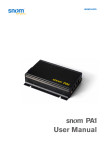
The key to preventing damage to the FLASH array or corruption of the
data contained in the memory is the programming voltage envelope
shown in Figure 9. Many of the problems that customers experience
with FLASH devices are due to a failure to ensure that their voltage
sources always meet these requirements.
Freescale Semiconductor, Inc...
The most important single thing to remember from this diagram is that
VFP and VDD should always be at the same level, except during an
actual program or erase cycle. Corruption of FLASH data is often
encountered when VFP is allowed to exceed VDD during the power-up
and power-down phases.
Conversely, if VFP is allowed to fall below .35 volts lower than VDD at any
time, damage to the FLASH array can occur.
30 ns MAXIMUM
13.5 V
12.6 V
VFP ENVELOPE
11.4 V
VDD ENVELOPE
COMBINED VDD AND VFP
tER
5.5 V
4.5 V
4.15 V
0V
–0.30 V
POWER
UP
NORMAL
READ
PROGRAM
ERASE
POWER
DOWN
Figure 9. Programming Voltage Envelope
NOTE:
Although Figure 9 shows a lower boundary of 4.15 volts on VFP during
the normal read phase, VFP always must be no more than .35 volts
below VDD. For example, If the operating voltage of VDD in the system is
5.2 volts, VFP can be no lower than 4.85 volts.
AN1836
21
For More Information On This Product,
Go to: www.freescale.com
Freescale Semiconductor, Inc.
Application Note
Freescale Semiconductor, Inc...
Example VFP
Protection
Circuitry
Figure 10 shows an example of a circuit which, if properly implemented,
can maintain the appropriate voltage levels on the VFP pin. This section
outlines the design for this circuit, what each component is intended to
do, and some design considerations when designing VFP pin protection.
Figure 10. VFP Supply Circuit
The general idea of this circuit implementation is to supply VFP from a
dc-dc converter. This dc-dc converter, like most, provides a shutdown
feature which allows the converter’s output to be shut off. When the
SHDN pin on the converter is pulled high, as the 10-kΩ pullup resistor
(R1) does, the output VOut is shorted to the VDD supply. This requires
that the programming and erasing routines assert a port pin on the MCU
to turn on the converter and supply the 12-volt programming voltage
during the programming or erasing cycle. Simple programming and
erasing routines, such as those shown earlier in this application note, will
no longer suffice.
By implementing this solution, VFP is tied to VDD on power-up and
power-down, ensuring that they rise and fall together. Capacitors C5 and
C6 are the normal decoupling capacitors on the VDD supply lines. C3 is
used to reduce electromagnetic interference (EMI) in the circuit. If C3 is
too large, VFP will not be allowed to fall with VDD, potentially causing data
AN1836
22
For More Information On This Product,
Go to: www.freescale.com
Freescale Semiconductor, Inc.
Application Note
Programming Voltage Supply Considerations
corruption in the FLASH array. (Refer to Figure 11.) C4 is where the
dc-dc converter stores charge to supply VOut to the target device. The
supply must be able to source approximately 30 mA of current for at least
20 µs (based on programming cycle requirements) and 4 mA of current
for at least 10 ms (based on erase cycle requirements).
Freescale Semiconductor, Inc...
A certain degree of experimentation might be required when selecting
C4 and C3. When trying different capacitor values, always monitor the
effects on VFP decay during power-down and current supplied to the VFP
pin.
R1 must be no larger than 10 kΩ, to make certain that the SHDN pin on
the dc-dc converter is never allowed to fall below VDD unless the output
pin of the microcontroller is driven low. The external pullup ensures this
behavior, no matter what port pin is used on the microcontroller or what
the internal structure of that pin looks like. Without a strong enough
pullup resistor on R1, the voltage on the SHDN pin might drop during a
reset event, causing the dc-dc converter to activate and begin driving the
voltage on VOut to begin to rise to 12 volts. This would result in data
corruption in the FLASH.
NOTE:
Figure 10 is different from the recommended circuit shown in
information about ST662A from ST Microelectronics, but it is correct.
The change is in the location of the capacitor C4, which is now placed
between VDD and VFP. This change was implemented with the
cooperation of ST Microelectronics to aid in tracking a rapidly falling VDD
voltage level, such as in Figure 11 and Figure 12. This circuit also has
been verified with the Maxim Integrated Products device (MAX662).
AN1836
23
For More Information On This Product,
Go to: www.freescale.com
Freescale Semiconductor, Inc.
Freescale Semiconductor, Inc...
Application Note
Figure 11. VFP Exceeding VDD during Power-Down
Be certain that VFP decays with VDD, as shown in Figure 12, as new
capacitance values are tested. The rate of decay of the VDD supply
powering down will help define how large the C3 capacitance can be
made.
AN1836
24
For More Information On This Product,
Go to: www.freescale.com
Freescale Semiconductor, Inc.
Freescale Semiconductor, Inc...
Application Note
Programming Voltage Supply Considerations
Figure 12. VFP Tracking VDD during Power-Down
When checking to ensure that the reservoir capacitance value of C4 is
not too low, the voltage level of VFP can be monitored during an initial
erase and a write pulse. Remember that the largest current draw on
erasing is when all of the bits of the FLASH are programmed to 0.
Conversely, the highest programming current is seen when
programming all the bits to 0 from the erased state of 1. The user should
look at this on an oscilloscope, due to the brevity of the pulses. Using a
port pin or the SHDN signal may be useful to trigger the scope when the
pulses are fired. If the voltage dips below 11.4 volts, the capacitance
used can be increased, but be sure to verify that decay rates of VDD and
VFP are still the same. If VFP is declining with each successive pulse, try
inserting some delays between each pulse to allow the charge pump to
recharge.
AN1836
25
For More Information On This Product,
Go to: www.freescale.com
Freescale Semiconductor, Inc.
Application Note
The solution shown in this application note uses the ST662A dc-dc
converter, but any similar device will work. Some other options are the
LTC1262C from Linear Technology Corporation or the MAX662 from
Maxim Integrated Products, Inc.
Alternative VFP Circuitry
Freescale Semiconductor, Inc...
Another option to placing a dc-dc converter on the application board for
in-circuit reprogramming is to supply VFP from outside the target system.
This can be achieved by using something similar to the circuit shown in
Figure 13. This solution requires that the BDM (background debug
mode) connections be made on the target board to allow for connection
of a BDM-compliant debug tool, as well as a VFP supply. Again, as long
as the VFP envelope rules are adhered to, this circuit will work well.
Also, bear in mind that a voltage regulator on VDD must be able to accept
the 700 µA of current or so which will flow upward through R2 during a
program or erase cycle, preventing it from being injected back into the
microcontroller.
AN1836
26
For More Information On This Product,
Go to: www.freescale.com
Freescale Semiconductor, Inc.
Freescale Semiconductor, Inc...
Application Note
Other FLASH Hardware Device Considerations
Figure 13. VFP Supplied from External Source
through BDM Interface
NOTE:
The diode D1 shown in Figure 13 must have a forward bias drop of no
greater than .35 volts to maintain the proper VFP to VDD voltage
relationship at all times. Diodes such as the 1N5818 or 1N5819 will work
and typically have even lower voltage drops at low current.
Other FLASH Hardware Device Considerations
Some hardware facts and details are worth mentioning here.
For instance, the M68HC12 Family uses a 1.5T FLASH technology. For
a more detailed description of this and other NVM technologies, refer to
the application note Non-Volatile Memory Technology Overview,
Freescale document order number AN1837/D.
Without getting into the level of detail provided in that document, the
practical side of some hardware considerations is included here. Topics
AN1836
27
For More Information On This Product,
Go to: www.freescale.com
Freescale Semiconductor, Inc.
Application Note
covered are the lifetime of the FLASH memory itself and the effects of
age and usage on the FLASH array. Also important to discuss are the
failure mechanisms involved when VFP is out of acceptable ranges and
testing for marginally programmed memories.
Freescale Semiconductor, Inc...
FLASH Lifetime
The main purpose of NVM is long-term storage of programs and data.
As a result, it is of prime concern to the application designer to know how
long that information will be stored correctly. Freescale guarantees a
FLASH data retention lifetime of 10 years for properly programmed data,
based on an average operating temperature of 70oC.
Since FLASH EEPROM is also electrically erasable, it is ideally suited
for in-circuit updating and rapid code modifications. The memory does,
however, have a finite number of program and erase cycles it can be put
through before it fails. Freescale guarantees 100 program/erase cycles
on the MC68HC912B32 device, which is based on 125°C.
Effects of Age
on FLASH Array
As the FLASH memory’s bitcells are written and erased over many
cycles, they tend to "age." The primary effect is that over time, gradually,
more and more erase or programming pulses are required to erase or
program the bitcell. This has been taken into account in the algorithms
for programming and erasing. The algorithms ensure that only the
fewest number of pulses required are applied to the device. As the
device ages, the number of pulses required will continue to rise until it
exceeds the specified limit in the electrical characteristics of the part.
Once this has happened, the part is no longer able to be modified within
specifications. Eventually, if the memory is continually written and
erased, some of the bitcells will become completely saturated and
unable to be modified regardless of the number of pulses applied to
them.
Possible Failure
Mechanisms
As has already been discussed, preventing data disturbance and
damage to the FLASH array is of ultimate concern. If VFP is improperly
managed, either corruption of data or damage is likely to occur.
A brief mention should be made of some of the consequences of
improperly controlled voltage sources. For instance, if VFP is allowed to
AN1836
28
For More Information On This Product,
Go to: www.freescale.com
Freescale Semiconductor, Inc.
Application Note
Other FLASH Hardware Device Considerations
fall more than .35 volts below VDD at any time, it can lead to pad-driven
latchup conditions or even damage to the VFP input pad. This could
result in improper programming, reduced current capability on the VFP
pin, or other types of damage to the VFP pin.
Freescale Semiconductor, Inc...
Also important to remember is that during power-up or power-down,
when VDD is below 4.5 volts, the MCU logic could potentially be in an
unknown state, and it might cause the voltage on the VFP pin to be
applied to the array inadvertently, causing data disturbance in the
FLASH array.
Testing
for Marginally
Programmed
FLASH
Some customers return devices claiming defective memory cells, since
the .s19 files won’t verify because of bits that don’t seem to be
programmed or that seem to change state after a good deal of time has
passed after programming. Generally, these returns are caused by
inadequately programmed FLASH cells. This can be due to improper
programming routines which do not meet the requirements of Motorola’s
programming algorithm or inadequate programming voltage power
supplies. However, if the programming algorithms and power supply
requirements outlined in this application note are adhered to, marginal
programming should not be a concern.
Marginally programmed devices would, by their very nature, tend to
allow bitcells to change state over time, since only enough charge was
transferred to allow the cell to read properly immediately after
programming. If these bit flipping symptoms are experienced, there are
methods to help determine if devices are not being adequately
programmed.
If there is a reason to believe that some devices might be marginally
programmed, a simple test can be run to determine whether the FLASH
is strongly or marginally programmed. The method is not exact, but it can
be effective in detecting marginally programmed parts, relative to
strongly programmed ones. Most importantly, this test should be used to
help identify insufficient programming voltage supply designs.
Contact a salesperson or field applications engineering representative to
determine if these testing methods are appropriate to your situation.
AN1836
29
For More Information On This Product,
Go to: www.freescale.com
Freescale Semiconductor, Inc.
Application Note
It is vital to the success of these tests that the devices in question are
properly handled before the testing is performed. The devices should be
serialized and this data linked with each device:
•
VFP supply which was used with that device
•
Schematics of the VFP supply design, if an on-board supply was
used
•
Source code used to program and erase that device
Freescale Semiconductor, Inc...
Also, several control devices should be supplied for comparison
purposes, as the testing is a relative testing measure. If the VFP supply
is in question, as might be the case if a charge pump were used and the
design might be incapable of supplying adequate current, control
devices will need to use identical programming and erasing code but use
a bench top power supply with a large current sourcing capacity.
If the FLASH modifying code is in question, it is necessary for the
customer to verify that the code follows Motorola’s recommended
programming and erasing algorithms which were covered in this
document.
Once these things have been done, contact a salesperson or field
applications engineering representative to determine how to proceed
with this type of analysis. The information gathered in the bullet list here
is needed to analyze the results of testing for marginal programming.
AN1836
30
For More Information On This Product,
Go to: www.freescale.com
Freescale Semiconductor, Inc.
Application Note
Conclusion
Conclusion
This application note gives an overview of the basics of erasing and
programming the FLASH array on the MC68HC912B32 microcontroller.
Knowing these basics, it is easy to progress to writing a bootloader,
designing a field programming unit, or other application which needs to
manipulate the FLASH memory.
Freescale Semiconductor, Inc...
In addition to the programming and erasing algorithms, this document
covers many of the hardware concerns relating to the programming
voltage supply and preventing data corruption or damage to the FLASH
memory. Several examples of VFP supply management have been given
for reference to properly control programming power supplies while
programming the M68HC12 Family and related devices.
For an example of a serial bootloader for this microcontroller, refer to
Serial Bootloader for Reprogramming the MC68HC912B32 FLASH
EEPROM, Freescale document order number AN1718/D.
AN1836
31
For More Information On This Product,
Go to: www.freescale.com
Freescale Semiconductor, Inc.
N O N - D I S C L O S U R E
Freescale Semiconductor, Inc...
A G R E E M E N T
R E Q U I R E D
Application Note
How to Reach Us:
Home Page:
www.freescale.com
E-mail:
[email protected]
USA/Europe or Locations Not Listed:
Freescale Semiconductor
Technical Information Center, CH370
1300 N. Alma School Road
Chandler, Arizona 85224
+1-800-521-6274 or +1-480-768-2130
[email protected]
Europe, Middle East, and Africa:
Freescale Halbleiter Deutschland GmbH
Technical Information Center
Schatzbogen 7
81829 Muenchen, Germany
+44 1296 380 456 (English)
+46 8 52200080 (English)
+49 89 92103 559 (German)
+33 1 69 35 48 48 (French)
[email protected]
Japan:
Freescale Semiconductor Japan Ltd.
Headquarters
ARCO Tower 15F
1-8-1, Shimo-Meguro, Meguro-ku,
Tokyo 153-0064
Japan
0120 191014 or +81 3 5437 9125
[email protected]
Asia/Pacific:
Freescale Semiconductor Hong Kong Ltd.
Technical Information Center
2 Dai King Street
Tai Po Industrial Estate
Tai Po, N.T., Hong Kong
+800 2666 8080
[email protected]
For Literature Requests Only:
Freescale Semiconductor Literature Distribution Center
P.O. Box 5405
Denver, Colorado 80217
1-800-441-2447 or 303-675-2140
Fax: 303-675-2150
[email protected]
Information in this document is provided solely to enable system and software
implementers to use Freescale Semiconductor products. There are no express or
implied copyright licenses granted hereunder to design or fabricate any integrated
circuits or integrated circuits based on the information in this document.
Freescale Semiconductor reserves the right to make changes without further notice to
any products herein. Freescale Semiconductor makes no warranty, representation or
guarantee regarding the suitability of its products for any particular purpose, nor does
Freescale Semiconductor assume any liability arising out of the application or use of
any product or circuit, and specifically disclaims any and all liability, including without
limitation consequential or incidental damages. “Typical” parameters which may be
provided in Freescale Semiconductor data sheets and/or specifications can and do
vary in different applications and actual performance may vary over time. All operating
parameters, including “Typicals” must be validated for each customer application by
customer’s technical experts. Freescale Semiconductor does not convey any license
under its patent rights nor the rights of others. Freescale Semiconductor products are
not designed, intended, or authorized for use as components in systems intended for
surgical implant into the body, or other applications intended to support or sustain life,
or for any other application in which the failure of the Freescale Semiconductor product
could create a situation where personal injury or death may occur. Should Buyer
purchase or use Freescale Semiconductor products for any such unintended or
unauthorized application, Buyer shall indemnify and hold Freescale Semiconductor
and its officers, employees, subsidiaries, affiliates, and distributors harmless against all
claims, costs, damages, and expenses, and reasonable attorney fees arising out of,
directly or indirectly, any claim of personal injury or death associated with such
unintended or unauthorized use, even if such claim alleges that Freescale
Semiconductor was negligent regarding the design or manufacture of the part.
For More Information On This Product,
Go to: www.freescale.com