1
Freescale Semiconductor, Inc.
HC08 Mon08
Target Interface
For More Information: www.freescale.com
Freescale Semiconductor, Inc.
Metrowerks, the Metrowerks logo, and CodeWarrior are registered trademarks of Metrowerks
Corp. in the US and/or other countries. All other tradenames and trademarks are the property of
their respective owners.
Copyright © Metrowerks Corporation. 2001. ALL RIGHTS RESERVED.
The reproduction and use of this document and related materials are governed by a license
agreement between Metrowerks Corp. and its licensee. Consult that license agreement before
use or reproduction of any portion of this document. If you do not have a copy of the license
agreement, contact your Metrowerks representative or call 800-377-5416.
Metrowerks reserves the right to make changes to any product described or referred to in this document without further notice. Metrowerks makes no warranty, representation or guarantee regarding the merchantability or fitness of its products for any particular purpose, nor does Metrowerks
assume any liability arising out of the application or use of any product described herein and specifically disclaims any and all liability. Metrowerks software is not authorized for and has not
been designed, tested, manufactured, or intended for use in developing applications where
the failure, malfunction, or any inaccuracy of the application carries a risk of death, serious
bodily injury, or damage to tangible property, including, but not limited to, use in factory
control systems, medical devices or facilities, nuclear facilities, aircraft or automobile navigation or communication, emergency systems, or other applications with a similar degree of
potential hazard.
Documentation stored on electronic media may be printed for non-commercial personal use only,
further to the license agreement related to the product associated with the documentation. Subject
to the foregoing non-commercial personal use, no portion of this documentation may be reproduced or transmitted in any form or by any means, electronic or mechanical, without prior written
permission from Metrowerks.
USE OF ALL SOFTWARE, DOCUMENTATION AND RELATED MATERIALS ARE SUBJECT TO THE METROWERKS END USER LICENSE AGREEMENT FOR SUCH PRODUCT.
How to Contact Metrowerks
Corporate Headquarters
World Wide Web
Ordering & Technical Support
Metrowerks Corporation
9801 Metric Blvd.
Austin, TX 78758
U.S.A.
http://www.metrowerks.com
Voice: (800) 377-5416
Fax: (512) 997-4901
For More Information: www.freescale.com
Freescale Semiconductor, Inc.
Table of Contents
1 HC08 Mon08 Target Interface
7
Overview. . . . . . . . . . . . . . . . . . . . . . . . . . . . . 7
Highlights . . . . . . . . . . . . . . . . . . . . . . . . . . . . 8
Requirements . . . . . . . . . . . . . . . . . . . . . . . . . . . 8
Mon08 Target Interface Demo . . . . . . . . . . . . . . . . . . . . 8
Introduction. . . . . . . . . . . . . . . . . . . . . . . . . . . 10
Interfacing Your System and a Target. . . . . . . . . . . . . . . . . 11
Hardware Connection . . . . . . . . . . . . . . . . . . . . . 11
Communication Configuration . . . . . . . . . . . . . . . . . . . 12
Communication Device . . . . . . . . . . . . . . . . . . . . 12
Loading the Mon08 Interface Component . . . . . . . . . . . . . . . 15
The Debugger Status Bar for the Mon08 . . . . . . . . . . . . . . 16
Mon08 Target Interface Menu Entries . . . . . . . . . . . . . . . . 17
Loading an application . . . . . . . . . . . . . . . . . . . . . 17
Reset . . . . . . . . . . . . . . . . . . . . . . . . . . . . 17
Mon08 Setup. . . . . . . . . . . . . . . . . . . . . . . . . 17
Set MCU Type . . . . . . . . . . . . . . . . . . . . . . . . 17
Memory Map . . . . . . . . . . . . . . . . . . . . . . . . 18
FLASH . . . . . . . . . . . . . . . . . . . . . . . . . . . 19
Command Files . . . . . . . . . . . . . . . . . . . . . . . . 20
Help . . . . . . . . . . . . . . . . . . . . . . . . . . . . 20
Advanced Mon08 Environment Setup . . . . . . . . . . . . . . . . 20
Communication Device and Reset Options Groups . . . . . . . . . . 21
Debugging Options Group . . . . . . . . . . . . . . . . . . . 24
Debugging Work Space Group . . . . . . . . . . . . . . . . . . 25
Supported Evaluation Hardware . . . . . . . . . . . . . . . . . . . 28
ICS08GP20/32 In-Circuit Simulator Board + M68HC08 Serial Programmer
(SPGMR) . . . . . . . . . . . . . . . . . . . . . . . . . . 30
M68HC08AZ32EVB / CanKit . . . . . . . . . . . . . . . . . . 30
MMC08 Monitor Mode Cable . . . . . . . . . . . . . . . . . . 32
Typical Initial Baudrates and Programming Rates . . . . . . . . . . . . 32
Resources Used by the Mon08 Target Interface . . . . . . . . . . . . . 34
Program Code . . . . . . . . . . . . . . . . . . . . . . . . 35
PTA0 . . . . . . . . . . . . . . . . . . . . . . . . . . . . 35
Vector Table . . . . . . . . . . . . . . . . . . . . . . . . . 35
Work Space . . . . . . . . . . . . . . . . . . . . . . . . . 36
Stack . . . . . . . . . . . . . . . . . . . . . . . . . . . . 36
Breakpoints . . . . . . . . . . . . . . . . . . . . . . . . . 37
MANUAL NAME
For More Information: www.freescale.com
Freescale Semiconductor, Inc.
Table of Contents
ROM Workspace Setup . . . . . . . . . .
Mon08 Target Interface Commands . . . . .
BAUDRATE . . . . . . . . . . . . . .
Short Description . . . . . . . . . . .
Syntax . . . . . . . . . . . . . . .
CATCHTRAPS . . . . . . . . . . . . .
Short Description . . . . . . . . . . .
Syntax . . . . . . . . . . . . . . .
FASTFLASH . . . . . . . . . . . . . .
RESET . . . . . . . . . . . . . . . .
Short Description . . . . . . . . . . .
Syntax . . . . . . . . . . . . . . .
WORKSPACE . . . . . . . . . . . . .
Short Description . . . . . . . . . . .
Syntax . . . . . . . . . . . . . . .
Mon08 Target Interface Environment Variables.
HC08GP20 . . . . . . . . . . . . . . .
Short Description . . . . . . . . . . .
Syntax . . . . . . . . . . . . . . .
Location . . . . . . . . . . . . . .
HWBPMODULEADR . . . . . . . . . .
Short Description . . . . . . . . . . .
Syntax . . . . . . . . . . . . . . .
Location . . . . . . . . . . . . . .
NOPWLOGFILE . . . . . . . . . . . .
Short Description . . . . . . . . . . .
Syntax . . . . . . . . . . . . . . .
Location . . . . . . . . . . . . . .
Dialog Variables . . . . . . . . . . .
.
.
.
.
.
.
.
.
.
.
.
.
.
.
.
.
.
.
.
.
.
.
.
.
.
.
.
.
.
.
.
.
.
.
.
.
.
.
.
.
.
.
.
.
.
.
.
.
.
.
.
.
.
.
.
.
.
.
.
.
.
.
.
.
.
.
.
.
.
.
.
.
.
.
.
.
.
.
.
.
.
.
.
.
.
.
.
.
.
.
.
.
.
.
.
.
.
.
.
.
.
.
.
.
.
.
.
.
.
.
.
.
.
.
.
.
.
.
.
.
.
.
.
.
.
.
.
.
.
.
.
.
.
.
.
.
.
.
.
.
.
.
.
.
.
.
.
.
.
.
.
.
.
.
.
.
.
.
.
.
.
.
.
.
.
.
.
.
.
.
.
.
.
.
.
.
.
.
.
.
.
.
.
.
.
.
.
.
.
.
.
.
.
.
.
.
.
.
.
.
.
.
.
.
.
.
.
.
.
.
.
.
.
.
.
.
.
.
.
.
.
.
.
.
.
.
.
.
.
.
.
.
.
.
.
.
.
.
.
.
.
.
.
.
.
.
.
.
.
.
.
.
.
.
.
.
.
.
.
.
.
.
.
.
.
.
.
.
.
.
.
.
.
.
.
.
.
.
.
.
.
.
.
.
.
.
.
.
.
.
.
.
.
.
.
.
.
.
.
.
.
.
.
.
.
.
.
.
.
.
.
.
.
.
.
.
.
.
.
.
.
.
.
.
.
.
.
.
.
.
.
.
.
.
.
.
.
.
.
.
.
.
.
.
.
.
.
.
2 FLASH PROGRAMMING
Introduction. . . . . . . . . . .
The NVMC Graphical User Interface.
Introduction . . . . . . . . .
NVMC Dialog . . . . . . . .
Flash Module Handling . . . .
Configuration: FPP file loading .
TMP–4
37
40
40
40
41
41
41
42
42
43
43
43
43
43
43
44
44
44
44
44
45
45
45
45
46
46
46
46
47
53
.
.
.
.
.
.
.
.
.
.
.
.
.
.
.
.
.
.
.
.
.
.
.
.
.
.
.
.
.
.
.
.
.
.
.
.
.
.
.
.
.
.
.
.
.
.
.
.
.
.
.
.
.
.
MANUAL NAME
For More Information: www.freescale.com
.
.
.
.
.
.
.
.
.
.
.
.
.
.
.
.
.
.
.
.
.
.
.
.
.
.
.
.
.
.
.
.
.
.
.
.
.
.
.
.
.
.
53
53
53
55
57
58
Freescale Semiconductor, Inc.
Table of Contents
Loading an application in flash. . . . . . . . . . . . . . . .
Prepare and Load Your Application in Flash . . . . . . . . . . . .
Hardware Considerations . . . . . . . . . . . . . . . . . . .
HC12B32 . . . . . . . . . . . . . . . . . . . . . . . .
HC12D60 . . . . . . . . . . . . . . . . . . . . . . . .
HC12DG128 . . . . . . . . . . . . . . . . . . . . . . .
AM29F010 on HC08AZ32EVB (CanKit) . . . . . . . . . . .
Flash Programming CPU08 Derivatives and Password Security Issue
HC08AT60 / AS60-AZ60 Emulation . . . . . . . . . . . . .
HC08GP20 . . . . . . . . . . . . . . . . . . . . . . .
HC08GP32 . . . . . . . . . . . . . . . . . . . . . . .
About FPP Files . . . . . . . . . . . . . . . . . . . . . . .
Introduction . . . . . . . . . . . . . . . . . . . . . . .
Appendix A. . . . . . . . . . . . . . . . . . . . . . . . .
Structure of the FPP File . . . . . . . . . . . . . . . . . .
FLASH . . . . . . . . . . . . . . . . . . . . . . . . . .
Short Description . . . . . . . . . . . . . . . . . . . . .
.
.
.
.
.
.
.
.
.
.
.
.
.
.
.
.
.
.
.
.
.
.
.
.
.
.
.
.
.
.
.
.
.
.
3 Target Interface Command Files
Target Interface Command introduction . . .
Target Interface Command Files Description .
Startup Command File . . . . . . . .
Reset Command File. . . . . . . . .
Preload Command File . . . . . . . .
Postload Command File . . . . . . .
Vppon Command File . . . . . . . .
Vppoff Command File . . . . . . . .
Command Files dialog . . . . . . . . .
Associated Commands . . . . . . . . .
Associated Environment Variables . . . . .
60
61
62
62
63
64
65
66
67
68
68
69
69
70
70
73
73
81
.
.
.
.
.
.
.
.
.
.
.
.
.
.
.
.
.
.
.
.
.
.
.
.
.
.
.
.
.
.
.
.
.
MANUAL NAME
For More Information: www.freescale.com
.
.
.
.
.
.
.
.
.
.
.
.
.
.
.
.
.
.
.
.
.
.
.
.
.
.
.
.
.
.
.
.
.
.
.
.
.
.
.
.
.
.
.
.
.
.
.
.
.
.
.
.
.
.
.
.
.
.
.
.
.
.
.
.
.
.
.
.
.
.
.
.
.
.
.
.
.
.
.
.
.
.
.
.
.
.
.
.
.
.
.
.
.
.
.
.
.
.
.
.
.
.
.
.
.
.
.
.
.
.
81
82
82
82
83
83
84
84
85
86
89
TMP–5
Freescale Semiconductor, Inc.
Table of Contents
TMP–6
MANUAL NAME
For More Information: www.freescale.com
Freescale Semiconductor, Inc.
H C0 8 M o n 0 8 T a rg et I n t er f a ce
Overview
1
HC08 Mon08 Target
Interface
Overview
This document includes information on using the Mon08 Target
Interface. This document has these sections:
• The Mon08 Target Interface Demo section helps you to "quick" start
and connect the debugger with your hardware target, step by step.
• The Introduction section introduces the Mon08 Target Interface
concept.
• The Interfacing Your System and a Target section gives a small
overview on serial communication and supported hardware.
• The Communication Configuration section describes the minimal setup
to start communicating with your hardware.
• The Loading the Mon08 Interface Component section explain how to
set the Mon08 target interface within the debugger.
• The Mon08 Target Interface Menu Entries section describes the
different entries of the MON08 menu.
• The Advanced Mon08 Environment Setup section gives all details of
the Setup menu entry.
• The Supported Evaluation Hardware section gives a larger overview on
supported hardware and communication circuitry.
• The Typical Initial Baudrates and Programming Rates section gives
you tables with baudrates of typical CPU08 derivatives and masks.
• The Resources Used by the Mon08 Target Interface section explains
the Mon08 mechanism and resource requirements.
• The ROM Workspace Setup section explains how to handle undefined
ISR when debugging in ROM/Flash.
MON08 Target Interface
For More Information: www.freescale.com
MON08–7
Freescale Semiconductor, Inc.
HC 08 M on 08 T ar ge t I nt e r f ac e
Highlights
• The Mon08 Target Interface Commands section lists all Command
Line commands bound to the Mon08 Target Interface.
• The Mon08 Target Interface Environment Variables section lists all
.PJT project-file environment variables bound to the Mon08 Target
Interface.
• The FLASH PROGRAMMING section explains programming CPU08
derivatives using internal FLASH and EEPROM modules.
• The Target Interface Command Files section describes the Mon08
Target Interface command files.
Highlights
The HC08 Mon08 Target Interface currently supports this hardware:
• CanKit, M68HC08AZ32EVB Motorola Evaluation Board.
• ICS08GP20/32 In-Circuit Simulator Board + M68HC08 Serial
Programmer (SPGMR).
• any hardware target using a CPU08 derivative with onchip MON08
monitor. The section Supported Evaluation Hardware gives the
Motorola-defined serial interface and RS-232 circuitry
• MMC08 Monitor Mode Cable for interfacing the debugger and an
HC08.
Requirements
The HC08 Mon08 Target Interface communicates with the hardware
target using the RS-232 serial communication port of your computer.
Therefore, your computer should have an available COM port. You need a
minimal circuitry defined by Motorola (given in the section Supported
Evaluation Hardware) to interface your CPU08 derivative. More powerful
interfaces like the MMC08 Monitor Mode Cable can provide "hardware
external pin reset" and "debugger stop/halt" features, using an "RTS" RS232 line and IRQ chip pin through the RS-232 "break" signal.
Mon08 Target Interface Demo
1. Before starting the debugger, you must configure your hardware
target (based on CPU08 derivative) with the required serial
interface and RSR-232 leveller as shown in the section Supported
MON08–8
MON08 Target Interface
For More Information: www.freescale.com
Freescale Semiconductor, Inc.
H C0 8 M o n 0 8 T a rg et I n t er f a ce
Mon08 Target Interface Demo
Evaluation Hardware. Some targets, like the Cankit or the Serial
Programmer (SPGMR), initially have this interface.
2. Do NOT add a power supply to the hardware. Instead, connect your
target to your computer’s COM port using a standard serial cable.
3. After installation, you can use three Metrowerks HC08 Demo
Projects:
Cankit08: this project applies to the Cankit, M68HC08AZ32EVB
Motorola Evaluation Board.
MMC08 with AT60: this project applies to the AT/AS/AZ60 with
MMC08 Monitor Mode Cable. If you do not have an MMC08
interface, you can still start with this project.
Mon08 for GP20: this project applies to the GP20/GP32 with the
Serial Programmer (SPGMR). If you do not have a Serial
Programmer, you can still start from this project.
4. Open the demo project that corresponds to your available hardware.
5. When using AT/AS/AZ60 derivatives, you must configure the
processor in the desired mode: set the onchip CONFIG-2 register
to AS or AZ emulation and set the AZxx bit and the MSCAND bit
in the "startup.cmd" command text file of your current project.
The debugger requires these settings in order to start the processor
immediately in the proper mode. For example, in this command
file, insert the command "wb 0xFE09 0x01" to force CAN and
AZ60 mode. You can edit the "startup.cmd" file with the
current text editor for your project.
6. Start the debugger.
7. As the hardware has no power yet, the Communication
Configuration dialog box automatically appears. At this point, set
the correct communication port in the Communication Device
field, such as COM1 or COM2.
8. You must provide a correct initial baudrate to open
communications with the onchip MON08 monitor. The Typical
Initial Baudrates and Programming Rates section gives you tables
with baudrates of typical CPU08 derivatives and masks. Check this
table to find the initial baudrate that matches your hardware,
derivative mask, and so on.
9. Set the initial baudrate value in the Initial Baud Rate field.
10.Check the Password checkbox and fill the password boxes with 00
00 00 00 00 00 00 00 for GP20, AT/AS/AZ60. If you use a GP32,
the factory password is FF FF FF FF FF FF FF FF.
11.If you connect the PTC3 pin of your derivative to logical 1, you
can speed up communications by using the valid values given in the
MON08 Target Interface
For More Information: www.freescale.com
MON08–9
Freescale Semiconductor, Inc.
HC 08 M on 08 T ar ge t I nt e r f ac e
Introduction
Typical Initial Baudrates and Programming Rates section.
Therefore, check the Initialize PLL checkbox. This feature does
not work with GP20/GP32 derivatives.
12.More hardware-related settings:
13.Check the Use RTS checkbox only when using the MMC08
Monitor Cable.
14.Check the Use DTR checkbox only when using the M68HC08
Serial Programmer (SPGMR).
15.All other checkboxes and editboxes do not apply to establishing
initial communications with your CPU08 derivative. Leave these
settings as initially configured for the project.
16.Power on your hardware target, then press the Connect button in
the dialog. box. The debugger starts communicating with the
onchip monitor. The Memory component window fills with values.
CPU registers appear in the Register component window.
Assembler instructions appear in the Assembly component
window.
17.Loading application in RAM: At this point, you can load a demo
application into RAM by choosing the MON08 > Load... menu
command.
18.Set a breakpoint in your source code. You can run the debugger by
clicking the Start/Continue button. You cannot always "halt" the
debugger/derivative without setting a breakpoint, however, using
the Cankit or the MMC08 Monitor Cable does allow breakpointfree halting. Otherwise, you need specific hardware to forward RS232 break signals to the IRQ pin of the derivative. See the section
Supported Evaluation Hardware for further details.
19. Loading application in FLASH: You can load a demo
application in onchip FLASH (AT/AS/AZ60, GP20/32) or Cankit
AM29F010 external flash by choosing the MON08 > Flash... menu
command. In the Non Volatile Memory Control Dialog, click the
Load... button and choose the application to load in flash. Note that
you need a license for the Flash Programming utility. In demo
mode, it has a 1-kilobyte limit.
Introduction
Another advanced feature of the debugger for embedded-system
development is its ability to load different Framework targets. This
document introduces the Mon08 Target Interface for the M68HC08.
MON08–10
MON08 Target Interface
For More Information: www.freescale.com
Freescale Semiconductor, Inc.
H C0 8 M o n 0 8 T a rg et I n t er f a ce
Interfacing Your System and a Target
The Mon08 Target Interface component is an interface the debugger uses
to communicate with an external system known as the target system.
With this interface, you can download an executable program from the
debugger environment to an external target system based on a Motorola
MCU that executes it. The debugger also reflects feedback of the real
target-system behaviour.
The debugger supervises and monitors the MCU of the target system, that
is, it controls CPU execution. You can read and write internal/external
memory, single-step/run/stop the CPU, and set breakpoints in the code.
NOTE
Unconcerned Components As the code executes on an external MCU, memory
statistics are not available to the Mon08 Target Interface component.
Therefore, Profiling, Coverage analysing, watchpoints and I/O simulation do not
work with the Mon08 component.
Interfacing Your System and a Target
Hardware Connection
The host is set up as a data terminal, that is, it sends data on the TxD lead
and receives data on the RxD lead. A normal serial cable connects the
CanKit Evaluation Board (M68HC08AZ32EVB), Serial Programmer
(SPGMR), or AVNET ADS boards. However, if you connect another
target system (like AZ_EVA MOTHER BOARD + HC08 derivatives like
AT60/AS60/AZ60), you need an additional communication hardware
interface in order to connect to the on-chip monitor of the 68HC08
(Mon08). Please see also Supported Evaluation Hardware section.
Please refer to the Monitor section of the CPU08 Manual, section 11:
MONITOR ROM from Motorola for additional information.
To use all features available from the Mon08 Target Interface, you need
some additional hardware. The evaluation board M68HC08AZ32EVB already
includes this hardware. Please see the section Supported Evaluation
Hardware for additional information.
WARNING!
MON08 Target Interface
For More Information: www.freescale.com
MON08–11
Freescale Semiconductor, Inc.
HC 08 M on 08 T ar ge t I nt e r f ac e
Communication Configuration
NOTE
The M68HC08AZ32EVB (CanKit) has 2 serial-port connectors. You must connect
your PC to the P2 connector of the EVB board.
NOTE
There are other available target-interface components (such as for the
MMDS0508 and MMEVS0508).
Communication Configuration
In a general way, the debugger automatically configures communication
with the Target System. If you configure the default communication setup,
the following dialog appears. You can also open this dialog by choosing
MON08 > Setup... or MON08 > Connect... from the debugger menu.
Ensure that you correctly configure the parameters on your host computer.
Make sure to set the correct serial-communication device, otherwise, the
debugger cannot communicate with the target.
Communication Device
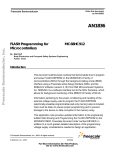
If the host and target are disconnected, the expected communication device
does not establish the connection, or, in a general way, the communication
fails, the dialog box shown in Figure 1.1 appears in the debugger.
MON08–12
MON08 Target Interface
For More Information: www.freescale.com
Freescale Semiconductor, Inc.
H C0 8 M o n 0 8 T a rg et I n t er f a ce
Communication Configuration
Figure 1.1
Communication and Debug options Setup
Settings in this dialog box vary according to the demo projects delivered
with your installation.
1. Enter an available communication device in the Communication
Device edit box. For a PC, enter any valid communication device
(COM1, COM2, etc.).
2. Set the Initial Baud Rate of your HC08 board, as specified by the
Motorola Evaluation board User’s Manual, in the Reset Options
group.
WARNING!
The initial baudrate depends on the ROM monitor version and the supplied
oscillator. You should specify an exact initial baudrate value and not round it. The
"Actual" field shows the baudrate and the percentage of baudrate error. Keep this
error under 2.5%. The Typical Initial Baudrates and Programming
MON08 Target Interface
For More Information: www.freescale.com
MON08–13
Freescale Semiconductor, Inc.
HC 08 M on 08 T ar ge t I nt e r f ac e
Communication Configuration
Rates section gives you tables with baudrates of typical CPU08 derivatives and
masks.
NOTE
Note that the board baudrate depends on the supplied oscillator. If you change
the oscillator frequency, the baud rate scales accordingly, potentially resulting in
unsupported PC serial-communication rates
3. Check the password checkbox and enter the Mon08 password.
Some HC08 MCUs (AT/AS/AZ60, GP20, and so on) have security
measures built into the Mon08 that prevent unauthorized access to
onchip FLASH EEPROM. To enter the Mon08 of these devices
with FLASH access, you must supply a password after Power-On
reset, before executing any command. You must supply the
password values within the dialog box.
Enter: 00 00 00 00 00 00 00 00
This example always matches when the flash memory is empty (not
programmed, with all bytes set to 0x00).
IMPORTANT: The GP32 derivative has all bytes set to 0xFF when not
programmed. Therefore blank/factory password is FF FF FF FF FF
FF FF FF.
NOTE
Some derivatives require a password in order to allow access to the MCU, even if
those derivatives do not check values. In such cases, you have to set the
password option, but the value of all bytes can be 00!
NOTE
You must establish the connection immediately following MCU Power-on reset
(power off + power on, NOT software or Reset pin toggle!). In this case, only the
onchip Mon08 monitor checks the password.
1. Set Debugging Options group: check the Initialize PLL checkbox
and choose the the baudrate multiplier from the dropbox (like “6”
to reach “28800” baud in a debugging session, with an initial
baudrate of 4800 baud). This configuration sets up the MUL bits in
the PLL programming register (PPG) to increase the CPU clock
rate and therefore the debugging baudrate. Note that the dropbox
contains only estimated possible baudrate factors. Do not overspeed
the CPU, otherwise the PC will no longer communicate with the
MON08–14
MON08 Target Interface
For More Information: www.freescale.com
Freescale Semiconductor, Inc.
H C0 8 M o n 0 8 T a rg et I n t er f a ce
Loading the Mon08 Interface Component
board. The Typical Initial Baudrates and Programming
Ratessection gives you tables with baudrates of typical CPU08
derivatives and masks.
NOTE
This feature is not available on GP20 and GP32 derivatives, so uncheck the
"Initialize PLL" checkbox when using these derivatives.
2. Usage of RTS: check this checkbox only when using the MMC08
Monitor Cable.
3. Usage of DTR: check this checkbox only when using the
M68HC08 Serial Programmer (SPGMR).
4. All other checkboxes and editboxes do not apply to establishing
initial communication with your HC08 MCU.
If the debugger loses the connection with the target, choose MON08 >
Connect... from the menu to open the Advanced Mon08 Environment
Setup dialog to re-connect.
NOTE
f the MCU requires a password, you must reset the target (hardware reset) before
attempting to connect!
Loading the Mon08 Interface Component
As with any other target, you can use the Target menu to load the Mon08
Target Interface component by choosing Component > Set Target...
Mon08, or you can set it as a default target in the .PJT project file that
resides in the current project directory.
Example of .PJT project file.
[Environment Variables]
...
Target=mon08
...
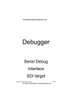
Set the target in the .PJT project file as shown above. If the target is
undefined, load the Mon08 Target Interface component interactively by
clicking the Component menu, choosing Set Target... like shown in
Figure 1.2, and selecting the Mon08 target component.
MON08 Target Interface
For More Information: www.freescale.com
MON08–15
Freescale Semiconductor, Inc.
HC 08 M on 08 T ar ge t I nt e r f ac e
Loading the Mon08 Interface Component
Figure 1.2
Set Target
The MON08 menu shown in Figure 1.3, item replaces the Target menu
item after loading completes.
Figure 1.3
Mon08 menu
A subsequent section, Mon08 Target Interface Menu Entries, explains the
different entries in the MON08 menu.
The Debugger Status Bar for the Mon08
After the IDE loads the Mon08 Target Interface component, specific
information appears in the debugger status bar shown in Figure 1.4 . The
baudrate of the serial communication, the selected CPU derivative
(according to selected MCU ID), and the debugger status (target status)
appear from left to right in the status bar.
Figure 1.4
MON08–16
Debugger Status Bar for the Mon08
MON08 Target Interface
For More Information: www.freescale.com
Freescale Semiconductor, Inc.
H C0 8 M o n 0 8 T a rg et I n t er f a ce
Mon08 Target Interface Menu Entries
Mon08 Target Interface Menu Entries
This section describes the Mon08 Target Interface Menu Entries shown
in Figure 1.5
Figure 1.5
Mon08 Target Interface Menu Entries
Loading an application
Choose MON08 > Load... to load the application you wish to debug, such
as an .ABS file or an S-Record file (see also the debugger user manual).
Reset
The command MON08 > Reset... initializes the PC with the reset-vector
value and sets the status register to the reset value. Since you cannot use a
Mon08 command to execute a real target reset, the debugger directly sets
the registers, but does not reset any external hardware. The debugger can
set the stack pointer (SP) to the reset value (0xFF) only after you enable the
workspace.
Mon08 Setup
Choosing MON08 > Setup... opens the Communication Configuration
dialog. Please see the section Advanced Mon08 Environment Setup.
Set MCU Type
The Set MCU Type... entry lets you choose your application’s current
CPU derivative like shown in Figure 1.6. You must perform this task
MON08 Target Interface
For More Information: www.freescale.com
MON08–17
Freescale Semiconductor, Inc.
HC 08 M on 08 T ar ge t I nt e r f ac e
Mon08 Target Interface Menu Entries
manually. The selected CPU derivative appears in the status bar. This
selection is important, as it determines the matching memory-map file for
the loaded CPU derivative. Please see the Memory Map section below.
Figure 1.6
NOTE
MCU selection
Select the AT60 MCU type even when using AS60 or AZ60 derivatives, as the
AT60 emulates both MCUs.
Memory Map
The Memory Map... entry lets you choose the CPU-derivative memory
map according to the CPU derivative you selected in the MCU Selection
dialog box shown in Figure 1.7 (if you checked the Auto select according
to MCU-Id checkbox) or according to the latest file you loaded by clicking
the Load... button.
MON08–18
MON08 Target Interface
For More Information: www.freescale.com
Freescale Semiconductor, Inc.
H C0 8 M o n 0 8 T a rg et I n t er f a ce
Mon08 Target Interface Menu Entries
Figure 1.7
MCU selection
NOTE
The CanKit board settings contain an adapted CanKit08.mem memory-map file.
You can edit the memory-map file: click the Add, Update, and Delete
buttons to modify an item in the memory-module list. A well-defined
memory map prevents debugger memory-access problems, as it does not
access undefined areas and ignores defined area types. Note that accessing
protected areas on some HC08 derivatives resets the on-chip Monitor. You
must not declare these areas in the memory map.
Click the Save... button to save your memory-map file. The IDE saves the
latest memory-map dialog-box settings in your current project. To reload in
a next session your personalized memory-map file, save it with a new name
and uncheck the Auto select according to MCU-Id checkbox before
closing the dialog box.
After installation, the IDE stores in the \PROG\MEM directory the
predefined memory-map files (*.MEM) that match MCU-IDs.
FLASH
• The Flash... entry applies to the FLASH / Non Volatile Memory
Control Utility and opens the NVMC Dialog, which lets you write and
erase FLASH and EEPROM modules. Please see the FLASH
PROGRAMMING section, which explains how to program a CPU08
derivative’s internal FLASH and EEPROM modules.
MON08 Target Interface
For More Information: www.freescale.com
MON08–19
Freescale Semiconductor, Inc.
HC 08 M on 08 T ar ge t I nt e r f ac e
Advanced Mon08 Environment Setup
Command Files
Select Command Files... to display the Command Files dialog dialog box.
Help
Select Help to open the Mon08 Target Interface Help File.
Advanced Mon08 Environment Setup
The Mon08 target lets you set up debugging features, such as catching
traps/interrupts, halting programs using external IRQ servicing, placing
debugger workspaces with different workspace init modes, backing up
passwords and warnings, and multiplying baudrates.
Choosing MON08 > Setup... opens the Communication and Debug
Option Setup dialog shown in Figure 1.8.
MON08–20
MON08 Target Interface
For More Information: www.freescale.com
Freescale Semiconductor, Inc.
H C0 8 M o n 0 8 T a rg et I n t er f a ce
Advanced Mon08 Environment Setup
Figure 1.8
Communication and Debug Option Setup
Communication Device and Reset Options
Groups
Communications Baudrate
Early in a session, choose the baudrate at which the host computer
communicates with the Mon08 target, because the system most efficiently
operates at the maximum baudrate that the host computer and target MCU
support. The debugger automatically detects the current baudrate when
starting to communicate with the Mon08 target. If communication fails, the
debugger automatically adapts the baudrate until communication begins
with the host computer. If automatic detection fails, you can manually
modify the baudrate.
MON08 Target Interface
For More Information: www.freescale.com
MON08–21
Freescale Semiconductor, Inc.
HC 08 M on 08 T ar ge t I nt e r f ac e
Advanced Mon08 Environment Setup
Baudrate Modification:
1. Enter an available communication device in the Communication
Device edit box. For a PC, enter any valid communication device
(COM1, COM2, etc.).
2. Set the Initial Baud Rate of your HC08 board as specified in your
HC08 derivative datasheet (General Release Specification book) in
the Reset Options group. The Typical Initial Baudrates and
Programming Rates section gives you tables with baudrates of
typical CPU08 derivatives and masks.
WARNING!
The initial baudrate depends on the ROM monitor version, the constructor chip
mask, and the supplied oscillator. You should specify an exact initial baudrate
value and not be round it. The "Actual" field shows the baudrate and the
percentage of baudrate error. Keep this error under 2.5%.
NOTE
Note that the board baudrate depends on the supplied oscillator. If you change
the oscillator frequency, the baud rate scales accordingly, potentially resulting in
unsupported PC serial-communication rates.
You can increase the communication baudrate between the debugger and
the MCU when changing the MCU’s PLL configuration. Please refer to the
following sections, Debugging Options Group and PLL Baudrate
Multiplying.
Password
Some HC08 MCUs (AT/AS/AZ60, GP20, and so on), have security
measures built into the Mon08 that prevent unauthorized access to onchip
FLASH EEPROM. To enter the Mon08 of these devices with FLASH
access, you must supply a password after Power-On reset, before
executing any command. You must supply the password values within the
dialog box.
Changing password:
Check the password checkbox and enter the Mon08 password.
Enter: 00 00 00 00 00 00 00 00
MON08–22
MON08 Target Interface
For More Information: www.freescale.com
Freescale Semiconductor, Inc.
H C0 8 M o n 0 8 T a rg et I n t er f a ce
Advanced Mon08 Environment Setup
This example always matches when the flash is empty for AZ/AS/AT and
GP20 (not programmed, with all bytes set to 0x00).
WARNING!
The GP32 derivative has all bytes 0xFF when not programmed. Therefore blank/
factory password is FF FF FF FF FF FF FF FF
NOTE
Some derivatives require a password in order to allow access to the MCU even if
the values are not checked. In such a case, the password option also has to be
set but the value of all bytes can be 0x00!
NOTE
The connection must be done right after MCU Power-on reset (power off + power
on, NOT software or Reset pin toggle!): The password is only checked by the
onchip Mon08 monitor in this case.
Each time the debugger starts communicating with the on-chip Mon08
monitor, it backs up the memory-vector password specified in the
Password address edit box ($FFF6-$FFFD) to a log file called
PWLOG.TXT. This log file resides in your current project directory. The
debugger performs this backup each time you erase or program the flash
memory. If you do NOT require this logfile, insert the environment
variable 'NOPWLOGFILE=1' in the .PJT project file (in your current
project directory) at section [MON08]. Note that, for security purposes,
the debugger does not provide a dialog box for disabling this log file.
In the setup dialog box, you can also check the Warn when... checkbox to
have the debugger warn you when a password mismatch (at connection) or
modification (after programming or erasing) occurs.
You can also check the Autorefresh... checkbox to have the debugger
automatically update the password edit boxes with the newly modified
password.
NOTE
If you cannot access the Flash memory because you lost your password, you can
still use the Flash Programming dialog box to erase the Flash modules. After
erasing the modules, the Flash Programming dialog box returns "Bad Device" due
to the fact that the debugger still cannot access the Flash modules while reading
(always reading "AD"), and blank verification fails. To reset the Monitor onchip
security measures, power reset (power off + power on) your HC08 derivative, then
set up the Monitor HC08 with a "00 00 00 00 00 00 00 00" password (or FF FF FF
FF FF FF FF FF for GP32), and connect again to the hardware.
MON08 Target Interface
For More Information: www.freescale.com
MON08–23
Freescale Semiconductor, Inc.
HC 08 M on 08 T ar ge t I nt e r f ac e
Advanced Mon08 Environment Setup
Show Protocol
If you check the Show Protocol checkbox, the command-line window
reports all the commands and responses sent and received.
NOTE
Metrowerks support personnel may ask you to check the Show Protocol checkbox
and provide the command-line window information.
Debugging Options Group
PLL Baudrate Multiplying
Check the Initialize PLL checkbox and choose the baudrate multiplier
from the dropbox (like “6” to reach “28800” baud in a debugging session,
with an initial baudrate of 4800 baud). This configuration sets up the MUL
bits in the PLL programming register (PPG) to increase the CPU clock rate
and therefore the debugging baudrate. Note that the dropbox contains only
estimated possible baudrate factors. Do not overspeed the CPU, otherwise
the PC will no longer communicate with the board. The Typical Initial
Baudrates and Programming Ratessection gives you tables with baudrates
of typical CPU08 derivatives and masks.
NOTE
This feature is not available on GP20 and GP32 derivatives, so uncheck the
"Initialize PLL" checkbox when using these derivatives.
Traps catching
This option lets you pass control to the Mon08 for "not initialised"
exceptions or interrupts when checking Catch last.... For details, see the
section Debugging Work Space Group.
Use of IRQ
The Mon08 cannot halt a running program except when it hits a breakpoint
(SWI or break hardware) or when you reset it, however, using an additional
external circuit, you can generate an interrupt (IRQ) to stop the application
(if you enable interrupts). For details, please see the section Supported
Evaluation Hardware.
MON08–24
MON08 Target Interface
For More Information: www.freescale.com
Freescale Semiconductor, Inc.
H C0 8 M o n 0 8 T a rg et I n t er f a ce
Advanced Mon08 Environment Setup
Use of RTS
The Mon08 cannot reset some CPU derivatives (like AT60/AS60/AZ60),
however, with an additional external circuit (MMC08 Interface), you can
decode the RS-232 RTS signal and reset the CPU derivative. Check this
checkbox only when using the MMC08 Monitor Cable. For details see
the section Supported Evaluation Hardware.
Use of DTR
The M68HC08 Serial Programmer (SPGMR) can decode the RS-232 DTR
signal to reset the CPU derivative. Check this checkbox only when using
the M68HC08 Serial Programmer (SPGMR). For details see the section
Supported Evaluation Hardware.
Debugging Work Space Group
Debugging Work Space
You need a small debugging workspace for trap catching (including IRQ)
and stack-pointer editing in the Register component.
Check the Enable from... checkbox to extend Mon08 Target Interface
component features with a minimal workspace. Without a workspace, the
component cannot catch interrupts/traps and halt the application using the
external IRQ special hardware.
NOTE
The trap-catching mechanism involves making all interrupt vectors (without ISR)
point to an SWI - RTI instruction pair in a table, therefore, when an unhandled
interrupt occurs, program execution halts on an SWI instruction execution. The
monitor regains MCU control. The debugger can then use the current PC to
identify the falling interrupt.
This workspace can reside in RAM or in ROM/FLASH.
If you set a workspace in RAM and your vectors reside in RAM (debug
hardware), check the 2 lower check boxes (Initialize...) to have the
debugger initialize the workspace and vectors accordingly.
If the workspace and vectors reside in ROM or in Flash, you must program
them separately into this device, or you must initialise them at linking time.
You can link a workspace to the application (for an example, see the
MON08 Target Interface
For More Information: www.freescale.com
MON08–25
Freescale Semiconductor, Inc.
HC 08 M on 08 T ar ge t I nt e r f ac e
Advanced Mon08 Environment Setup
section ROM Workspace Setup). In this case, DO NOT check the 2 lower
check boxes (Initialize...).
With trap catching enabled and the MCU in monitor mode, the Mon08 uses
an SWI interrupt to automatically catch any hardware reset or software
interrupt. If you want to catch other interrupts/traps, enter in the Catch last
edit box the last vector that you want the debugger to intercept. Vectors are
numbered in decreasing vector addresses (that is, Reset = vector 0, SWI =
vector 1, IRQ = vector 2, and so on). This configuration sets up the vector
table to point all vectors from vector 3 (after IRQ) to the specified vector
into the workspace, where the Mon08 enters and halts the target program.
The Mon08 cannot halt a running program except when it hits a breakpoint
(SWI or break hardware) or when you reset it, however, you can use an
additional circuit to generate an interrupt on the IRQ input pin of the MCU.
If the vector for the IRQ points to a SWI in the workspace, the Mon08
activates and stops the application. Do not check the ‘Use IRQ’ check box
unless you have the required hardware (see the section Resources Used by
the Mon08 Target Interface and the section Supported Evaluation
Hardware). With the appropriate external hardware connected to the IRQ
pin of the MCU, the debugger sends a Break instruction through the serialcommunication link and raises an IRQ interrupt to stop the current running
application and transfer control back to the Mon08.
The Mon08 Target Interface component uses a minimal workspace of 4
bytes (for code to set the stack and reset the CPU). If you uncheck the
Enable... checkbox, the component uses no resources, but it deactivates all
extended features.
If you set the workspace address to a value like 0xFF00, the dialog box
displays an automatically evaluated range for external IRQ pin use, which
it determines according to the number of traps caught (see the section
Resources Used by the Mon08 Target Interface and the section Supported
Evaluation Hardware).
In summary,
Checking Enable....
- requires only 4 bytes for stack user handling using the Register window
Then checking Using IRQ...
MON08–26
MON08 Target Interface
For More Information: www.freescale.com
Freescale Semiconductor, Inc.
H C0 8 M o n 0 8 T a rg et I n t er f a ce
Advanced Mon08 Environment Setup
- requires 3 additional bytes to trap the IRQ interrupt
Then checking Catch last...
- requires no resources from last 1 to 3, as these are the last 3 ones: the
RESET interrupt, usually pointing the program-entry code in the linkerparameter file (reserved by the program), the SWI interrupt (reserved for
the Monitor), and the IRQ (already reserved when checking Using IRQ...).
Then these traps require 2 more bytes per trap.
NOTE
In the HC08A?60 demo sample files delivered with the CodeWarrior Installation,
IRQ use is disabled, since the Work Space is unused. On AT60/AS60/AZ60
derivatives, unset vectors reside in Flash EEPROM. As a consequence, the
RESET and IRQ vectors point to address 0x0000 (address 0xFFFF for GP32).
Without proper IRQ behaviour, the debugger cannot halt a program without using
breakpoints. Stopping the debugger generates an IRQ and call address 0x0000,
and eventually the communication fails, however, resetting the target generates a
hardware reset and restarts the Monitor. The Monitor then sets the PC to address
0x0000. Loading an application (.ABS) file sets the PC to the code-entry point.
See the section ROM Workspace Setupfor information about using
wsp.c and setting up the linker-parameter file.
Another Way to Trap "Undesired" Interrupts
You can create in your source program "Interrupt Service Routine"
functions for all derivative vectors. These functions must have the
instruction "asm SWI;" in order to stop the monitor. A matching vector in a
function triggers halting of the program.
For example, a C-source file with the code
#pragma TRAP_PROC
void Vector_5_ISR void {
asm SWI;
...
}
would have this corresponding code in the linker .PRM file:
...
VECTOR 5
Vector_5_ISR
/* ISR setup for vector 5 */
MON08 Target Interface
For More Information: www.freescale.com
MON08–27
Freescale Semiconductor, Inc.
HC 08 M on 08 T ar ge t I nt e r f ac e
Supported Evaluation Hardware
...
Supported Evaluation Hardware
The Mon08 Target Interface component can communicate with any
hardware target using an HC08 derivative with onchip Mon08 monitor.
You need a minimal circuitry to support serial communication between the
host PC and the HC08 derivative, as shown in Figure 1.9 (from the
Motorola Data Sheet).
MON08–28
MON08 Target Interface
For More Information: www.freescale.com
Freescale Semiconductor, Inc.
H C0 8 M o n 0 8 T a rg et I n t er f a ce
Supported Evaluation Hardware
Figure 1.9
Mon08 Target Interface component
MON08 Target Interface
For More Information: www.freescale.com
MON08–29
Freescale Semiconductor, Inc.
HC 08 M on 08 T ar ge t I nt e r f ac e
Supported Evaluation Hardware
ICS08GP20/32 In-Circuit Simulator Board +
M68HC08 Serial Programmer (SPGMR)
The Mon08 Target Interface is fully compatible with Motorola’s Serial
Programmer. The DTR signal of the RS-232 line carries out the hardware.
power reset.
You must check the Use DTR... checkbox to use this feature
NOTE
The "PLL Baudrate Multiplying" feature is not available on GP20 and GP32
derivatives, so uncheck the "Initialize PLL" checkbox when using these
derivatives.
M68HC08AZ32EVB / CanKit
This evaluation board contains a special circuit that can halt your
application and enter the Mon08, as explained in the section Advanced
Mon08 Environment Setup (using an external IRQ on the MCU). To use
this feature, check/enable/set up a minimal workspace and check the Use
IRQ... checkbox in the Advanced Mon08 Environment Setup dialog box.
The following schematic is a simplified derivative of the
M68HC08AZ32EVB Motorola Evaluation Board. The main addition to the
interface above is the handling of the IRQ signals. It detects a break signal
(> 10..20 ms) on the serial-communication interface and generates a short
pulse on the IRQ line (~10 µs). This pulse causes the evaluation board to
interrupt (halt) a running application program. See the electronic chart
shown in Figure 1.10.
MON08–30
MON08 Target Interface
For More Information: www.freescale.com
Freescale Semiconductor, Inc.
H C0 8 M o n 0 8 T a rg et I n t er f a ce
Supported Evaluation Hardware
Figure 1.10
Simplified schematic from the Motorola Evaluation Board
‘M68HC08AZ32EVB’.
MON08 Target Interface
For More Information: www.freescale.com
MON08–31
Freescale Semiconductor, Inc.
HC 08 M on 08 T ar ge t I nt e r f ac e
Typical Initial Baudrates and Programming Rates
MMC08 Monitor Mode Cable
The MMC08 Monitor Mode Cable (Every Design Consultancy Ltd,
www.everydesign.com) accesses the Monitor mode of the 68HC08
microcontroller.
In addition to providing the required RS-232 level shifting debugger
communication with the 68HC08, the cable contains additional circuitry
that gives the debugger additional control over the target system. When
using the MMC08, the debugger can generate an IRQ interrupt to halt
the 68HC08 and also reset (using the RS-232 RTS signal) the target
system (MCU pin RESET) as needed.
To use this feature, check/enable/setup a minimal workspace and check the
Use IRQ... checkbox in the Advanced Mon08 Environment Setup dialog
box.
You also need to check the Use RTS... checkbox to use the MCU reset
feature with the MMC08.
The HC08 Monitor Target Interface is fully compatible with the MMC08
interface.
NOTE
Other Metrowerks Target Interface components available for MMDS0508 and
MMEVS0508 can help you develop software for HC08 derivatives.
Typical Initial Baudrates and Programming Rates
Rates given below are average measured rates. When no value appears for
a PLL factor and a given Xtal, it indicates an unavailable setting.
Note that the PTC3 pin setup changes the communication rates by factors
of 2. When PTC3 = 0, the initial baudrate doubles, but you cannot use the
PLL module to increase communication rates, since the debugger derives
the internal clock signal from CGMXCLK (Xtal) and never from
CGMVCLK (PLL). When PTC3 = 0, DO NOT check the "Initialize
PLL..." checkbox. When PTC3 = 1, the debugger can derive the internal
clock signal from CGMVCLK (PLL) and multiply the initial baudrate
(when you check the "Initialize PLL..." checkbox).
IBR = initial baudrate
MON08–32
MON08 Target Interface
For More Information: www.freescale.com
Freescale Semiconductor, Inc.
H C0 8 M o n 0 8 T a rg et I n t er f a ce
Typical Initial Baudrates and Programming Rates
PLLx = PLL factor (only when PTC3=1). PLLx=2 column rates are also valid for
PTC3=0.
av = available but not measured.
HC908AZ60 mask 2J74Y
====================
available flash programming rates (bytes/s)
Xtal
PLLx=9
(Mhz)
IBR
IBR
PLL=13
(PTC3=1) (PTC3=0)
2
1811
3623
4
3623
7246
4.9152
4452
8904
188
8
7246
14492
>
PLLx=1
PLLx=2
PLLx=3
PLLx=4
PLLx=7
PLLx=8
(PTC3=0)
25
40
25
35
40
32
40
70
67
73
114
47
70
110
186
HC908AZ60 mask 8H62A
====================
available flash programming rates (bytes/s)
Xtal
PLLx=8
(Mhz)
IBR
IBR
> PLLx=1 PLLx=2
PLLx=10 PLLx=12 PLLx=15
(PTC3=1) (PTC3=0)
(PTC3=0)
2
1953
3906
98
115
137
4
3906
7812
166
221
4.9152 4800
9600
221
8
7812
15624
34
34
26
43
34
43
50
115
PLLx=3
PLLx=4
46
66
78
55
99
96
131
PLLx=5
PLLx=6
65
115
168
160
HC908GP20 mask 0J82S
====================
Xtal
(Mhz)
4.9152
IBR
Prog. rate(bytes/s)
9600
57 (48 with SPGMR)
HC908GP32 mask 3J20X
MON08 Target Interface
For More Information: www.freescale.com
MON08–33
Freescale Semiconductor, Inc.
HC 08 M on 08 T ar ge t I nt e r f ac e
Resources Used by the Mon08 Target Interface
====================
Xtal
(Mhz)
IBR
Prog. rate(bytes/s)
4.9152
9600
61 (with SPGMR)
M68HC08AZ32EVB (CanKit) HC908AZ0 mask 0H56A
===========================================
with external AM29F010 flash
============================
available flash programming rates (bytes/s)
Xtal
(Mhz)
IBR
4.9152
4800
WARNING!
PLLx=1
PLLx=2
PLLx=3
PLLx=4
33
av
av
av
PLLx=6
av
PLLx=8
av
PLLx=12
305
The FASTFLASH command (Fast flash programming option in NVMC dialog)
calls an alternate algorithm to program internal flash modules. Alternate
algorithms are (at this document edition time) available for HC908AZ60 (AS/AT)
and HC908GP32 derivatives. This alternate algorithm is usually faster and might
use a non standardised communication protocol on the same standardised (by
Motorola) physical layer.
Current performances (programming rates) with any mask and any initial
baudrate:
-HC908AZ60: 500 Bytes/s.
-HC908GP32: 2.4 kBytes/s.
Resources Used by the Mon08 Target Interface
The monitor program uses some target-system resources. There are four
basic monitor-program elements:
• Monitor code and vector table
• PTA0 pin
MON08–34
MON08 Target Interface
For More Information: www.freescale.com
Freescale Semiconductor, Inc.
H C0 8 M o n 0 8 T a rg et I n t er f a ce
Resources Used by the Mon08 Target Interface
• Stack and work space
• SWI (used for breakpoints)
Program Code
The monitor (Mon08) program code and some control registers reside in
the address range from 0xFE00 to 0xFEFF (see the CPU08 Manual,
section 11: MONITOR ROM). You must activate the code by applying a
high logic level on the IRQ pin. A part of the vector table gets remapped in
order to pass control to the monitor code (Reset and SWI vectors).
PTA0
For communication between host and target, serial communication occurs
through the PTA0 pin (see the CPU08 Manual, section 11: MONITOR
ROM).
Vector Table
The vector table resides in the address range from 0xFFC0 to 0xFFFF.
You should implement it as RAM (during development) to provide these
features:
1. loading the vector table of the user application
2. catching undefined traps and interrupts using the debugger
3. using the IRQ vector to stop the user code (see the Note below)
When you set the appropriate options and load the target component, the
monitor initializes the IRQ vector and 7 bytes of the workspace in order to
allow the debugger to modify the stackpointer (SP) and to catch the IRQ,
which it can use to halt your program. The monitor can initialize the rest of
the vector table (vectors 3 to 31) to allow the debugger to catch some or all
of the interrupts or exceptions (see the CATCHTRAPS command).
If your application does not initialize and use a vector, the Mon08 keeps
control (halts the application) and in response the debugger displays the
corresponding message.
If the vector table resides in Flash or (E)PROM, the monitor initializes the
vector table at link time and loads it together with the application (See the
section ROM Workspace Setup).
MON08 Target Interface
For More Information: www.freescale.com
MON08–35
Freescale Semiconductor, Inc.
HC 08 M on 08 T ar ge t I nt e r f ac e
Resources Used by the Mon08 Target Interface
NOTE
No Mon08 command stops your application from running (except when running
on a breakpoint or by a reset). To stop your application, you must add an
additional circuit to detect a break on the serial communication and generate an
IRQ. The Debugger then catches the IRQ and enters Mon08 (by initializing the
IRQ vector to point to the SWI instruction that enters the Mon08).
Work Space
The workspace extends Mon08 features. Allocate it in RAM to activate
these useful extensions. You can also allocate it in Flash or (E)PROM (see
the Advanced Mon08 Environment Setup and ROM Workspace Setup
sections).
Stack
The Mon08 and the application share the same stack. When Mon08 is
active, the monitor program occupies the top of the stack (see the figure
below).
The Mon08 occupies at most 13 bytes of the stack. It uses the first 6 bytes
to store the application registers and up to the following 7 bytes for
temporary storage of the Mon08. When the application runs, the Mon08
does not occupy any space in RAM (since no global variables exist).
MON08–36
MON08 Target Interface
For More Information: www.freescale.com
Freescale Semiconductor, Inc.
H C0 8 M o n 0 8 T a rg et I n t er f a ce
ROM Workspace Setup
NOTE
The stack pointer must always point to a RAM area to maintain stable Mon08 and
debugger behaviour!
Breakpoints
Use the software interrupt (SWI) instruction to implement breakpoints and
single-stepping of code. Your application cannot use the SWI.
ROM Workspace Setup
Read the section Debugging Work Space Group before reading this
section.
When the Workspace resides in RAM, the debugger should initialize that
workspace prior to using it. To configure this initialization, check the
corresponding option in the Setup dialog box. Checking these options
allow the debugger to initialize the workspace and the vector table.
When the Workspace resides in ROM or Flash memory, you must program
the workspace content into the device. You can accomplish this task
together with your application by linking the “wsp.o” file with your
application.
The Monitor demo files also include the “wsp.c/o” files.
Listing 1.1
Source code of “wsp.c” file
#define USE_IRQ
1
#define CATCH_TRAPS
1
#define WSP_SRT
(3 + 4*USE_IRQ)
#pragma CONST_SEG WorkSpace
const char _WSP_[] = {
0x94,
/* TXS
; move H:X into SP
0x83,
/* SWI
; enter monitor
0x80
/* RTI
; back to caller (done with DisabledStep)
#if USE_IRQ
,
0x2E,
/* BIL *0 ; wait until IRQ pin is high
0xFE,
0x83,
/* SWI
; enter monitor
0x80
/* RTI
; back to caller (done with DisabledStep)
#endif
#if CATCH_TRAPS
MON08 Target Interface
For More Information: www.freescale.com
*/
*/
*/
*/
*/
*/
MON08–37
Freescale Semiconductor, Inc.
HC 08 M on 08 T ar ge t I nt e r f ac e
ROM Workspace Setup
,
0x83,
0x80,
0x83,
0x80,
0x83,
0x80,
0x83,
0x80,
0x83,
0x80,
0x83,
0x80,
0x83,
0x80,
0x83,
0x80,
0x83,
0x80,
0x83,
0x80,
0x83,
0x80,
0x83,
0x80,
0x83,
0x80,
0x83,
0x80,
0x83,
0x80,
0x83,
0x80,
0x83,
0x80,
0x83,
0x80,
0x83,
0x80,
0x83,
0x80,
0x83,
0x80
/* SWI
/* RTI
/* SWI
/* RTI
/* SWI
/* RTI
/* SWI
/* RTI
/* SWI
/* RTI
/* SWI
/* RTI
/* SWI
/* RTI
/* SWI
/* RTI
/* SWI
/* RTI
/* SWI
/* RTI
/* SWI
/* RTI
/* SWI
/* RTI
/* SWI
/* RTI
/* SWI
/* RTI
/* SWI
/* RTI
/* SWI
/* RTI
/* SWI
/* RTI
/* SWI
/* RTI
/* SWI
/* RTI
/* SWI
/* RTI
/* SWI
/* RTI
; enter monitor
; back to caller (done with DisabledStep)
; enter monitor
; back to caller (done with DisabledStep)
; enter monitor
; back to caller (done with DisabledStep)
; enter monitor
; back to caller (done with DisabledStep)
; enter monitor
; back to caller (done with DisabledStep)
; enter monitor
; back to caller (done with DisabledStep)
; enter monitor
; back to caller (done with DisabledStep)
; enter monitor
; back to caller (done with DisabledStep)
; enter monitor
; back to caller (done with DisabledStep)
; enter monitor
; back to caller (done with DisabledStep)
; enter monitor
; back to caller (done with DisabledStep)
; enter monitor
; back to caller (done with DisabledStep)
; enter monitor
; back to caller (done with DisabledStep)
; enter monitor
; back to caller (done with DisabledStep)
; enter monitor
; back to caller (done with DisabledStep)
; enter monitor
; back to caller (done with DisabledStep)
; enter monitor
; back to caller (done with DisabledStep)
; enter monitor
; back to caller (done with DisabledStep)
; enter monitor
; back to caller (done with DisabledStep)
; enter monitor
; back to caller (done with DisabledStep)
; enter monitor
; back to caller (done with DisabledStep) */
*/
*/
*/
*/
*/
*/
*/
*/
*/
*/
*/
*/
*/
*/
*/
*/
*/
*/
*/
*/
*/
*/
*/
*/
*/
*/
*/
*/
*/
*/
*/
*/
*/
*/
*/
*/
*/
*/
*/
*/
*/
#endif
};
MON08–38
MON08 Target Interface
For More Information: www.freescale.com
Freescale Semiconductor, Inc.
H C0 8 M o n 0 8 T a rg et I n t er f a ce
ROM Workspace Setup
Listing 1.2
Example with LEDS.PRM sample
LINK leds.abs
NAMES leds.o start08.o wsp.o ansi.lib END
SECTIONS
Z_RAM = READ_WRITE 0x0080 TO 0x00FF;
MY_RAM = READ_WRITE 0x0100 TO 0x01FF;
MY_ROM = READ_ONLY
0xF000 TO 0xFEFF;
PLACEMENT
DEFAULT_ROM
INTO MY_ROM;
DEFAULT_RAM
INTO MY_RAM;
_DATA_ZEROPAGE, MY_ZEROPAGE INTO Z_RAM;
WorkSpace
INTO READ_ONLY
0xFF00 TO 0xFF30;
END
STACKSIZE 0x60
VECTOR 0 _Startup
VECTOR 1 0x0000 /* SWI, used by the Mon08, not by user */
VECTOR 2 _WSP_ OFFSET 3
/* IRQ vector handler */
VECTOR 3 _WSP_ OFFSET 7
/* PLL */
VECTOR 4 TimerInterrupt
/* PIT */
/* PIT int points to TimerInterrupt
function
VECTOR 5 _WSP_ OFFSET 11 /* TIMA CH0 */
VECTOR 6 _WSP_ OFFSET 13 /* TIMA CH1 */
VECTOR 7 _WSP_ OFFSET 15 /* TIMA CH2 */
VECTOR 8 _WSP_ OFFSET 17 /* TIMB CH0 */
VECTOR 9 _WSP_ OFFSET 19 /* TIMB CH1 */
VECTOR 10 _WSP_ OFFSET 21 /* TIMB Overflow */
VECTOR 11 _WSP_ OFFSET 23 /* SPI Receive */
VECTOR 12 _WSP_ OFFSET 25 /* SPI Transmit */
VECTOR 13 _WSP_ OFFSET 27 /* msCAN Wakeup */
VECTOR 14 _WSP_ OFFSET 29 /* msCAN Error */
VECTOR 15 _WSP_ OFFSET 31 /* msCAN Receive */
VECTOR 16 _WSP_ OFFSET 33 /* msCAN Transmit */
VECTOR 17 _WSP_ OFFSET 35 /* SCI Error */
VECTOR 18 _WSP_ OFFSET 37 /* SCI Receive */
VECTOR 19 _WSP_ OFFSET 39 /* SCI Transmit */
VECTOR 20 _WSP_ OFFSET 41 /* Keyboard */
VECTOR 21 _WSP_ OFFSET 43 /* ADC */
Initially in WSP.C, the Monitor catches all traps, as all vectors appear in
the .PRM files and point to the _WSP_ section. Note that each vector
points to different SWI/RTI instructions that the Monitor can properly
identify upon entry. In the .PRM file example above, the PIT timer vector
gets redirected to the TimerInterrupt function (in LEDS.C file).
MON08 Target Interface
For More Information: www.freescale.com
MON08–39
Freescale Semiconductor, Inc.
HC 08 M on 08 T ar ge t I nt e r f ac e
Mon08 Target Interface Commands
See the sample files LEDS.* for further details about interrupt handling.
You can undefine USE_IRQ and CATCHTRAPS if you choose not to use
them, but make sure to configure the correct offsets (all offsets
decremented by 4) if USE_IRQ is undefined. If CATCHTRAPS is
undefined, make sure to properly redirect the vectors in the .PRM file.
Mon08 Target Interface Commands
You can use the commands explained in this section in any command file,
such as STARTUP.CMD, or enter them in the Command Line component.
The debugger executes the startup command file STARTUP.CMD after
the Mon08 Target Interface loads. This file must reside in the current
project directory. You can use any debugger command in this file and use
the commands introduced in the debugger manual to set up the target
hardware before loading any application.
The Mon08 Target Interface has these specific commands:
BAUDRATE
CATCHTRAPS
FASTFLASH
RESET
WORKSPACE
You can enter these commands in the STARTUP.CMD file or in the
debugger Command Line component.
BAUDRATE
Short Description
sets the communication baud rate and the PLL factor
MON08–40
MON08 Target Interface
For More Information: www.freescale.com
Freescale Semiconductor, Inc.
H C0 8 M o n 0 8 T a rg et I n t er f a ce
CATCHTRAPS
Syntax
BAUDRATE rate [PLLfactor]
rate: Specifies the baud rate immediately after reset. You must specify
the exact baudrate and not round it:
PLLfactor: Specifies an initialization factor for the PLL (default value of
1).
Description
The BAUDRATE command sets the baud rate for communication between
the Mon08 and the host computer.
Set the Initial Baud Rate of your HC08 board (as specified by the Motorola
Evaluation board User’s Manual) in the Reset Options group.
NOTE
Note that the board baudrate depends on the supplied oscillator. If you change
the oscillator frequency, the baud rate scales accordingly, potentially resulting in
unsupported PC-serial communication rates!
The Typical Initial Baudrates and Programming Rates section gives you
tables with baudrates of typical CPU08 derivatives and masks.
example:BAUDRATE 4800 6
Changes the communication baud rate to 4800 and sets the debugging rate
to 28800.
CATCHTRAPS
Short Description
Initializes the vector table in order to allow the debugger to catch traps and
interrupts on vectors that the target application does not initialize.
MON08 Target Interface
For More Information: www.freescale.com
MON08–41
Freescale Semiconductor, Inc.
HC 08 M on 08 T ar ge t I nt e r f ac e
FASTFLASH
Syntax
CATCHTRAPS <MaxVector>
where MaxVector defines a range of vectors, from 2 .. MaxVector.
Examples:
CATCHTRAPS 7
catches vectors 2 to 7.
Description
The CATCHTRAPS command initializes selected exception vectors to
point to an exception handler which stops the target application. This halt
allows you to detect hardware or programming errors caused by
unexpected exceptions or interrupts.
The command allows you to specify a range of vectors that the debugger
must catch.
You need a workspace to store the exception handlers for each specified
vector. The WORKSPACE command sets up the base address of the
workspace.
Example
CATCHTRAPS 23
(included).
catches all vectors in the range 2 to 23
FASTFLASH
The selected application should only contain code matching ROM/FLASH
sections defined in the Memory Map dialog.
Example
FASTFLASH "c:\temp\all908gp32flash.sx"
MON08–42
MON08 Target Interface
For More Information: www.freescale.com
Freescale Semiconductor, Inc.
H C0 8 M o n 0 8 T a rg et I n t er f a ce
RESET
RESET
Short Description
resets the target MCU.
Syntax
RESET
Description
The RESET command initializes the PC with the value of the reset vector
and sets the status register to the reset value. Since no Mon08 command
can execute a real target reset, the debugger directly sets the registers and
does not reset any external Hardware. With the workspace enabled, you
can set the stack pointer (SP) to the reset value (0xFF) only.
Example
RESET
WORKSPACE
Short Description
defines the location and initialization of the workspace.
Syntax
WORKSPACE WSPAdr [;C][;L][;I][;D]
WSPAdr is the workspace address.
[;C]initializes the workspace after connecting to the Mon08.
[;L]initializes the workspace before loading the application code.
[;I]uses the IRQ to halt your application.
MON08 Target Interface
For More Information: www.freescale.com
MON08–43
Freescale Semiconductor, Inc.
HC 08 M on 08 T ar ge t I nt e r f ac e
Mon08 Target Interface Environment Variables
[;D]disables the workspace.
Description
This command defines the parameters of the Workspace (location,
activation, and initialization).
Example
WORKSPACE 0xFF00 ;C ;L
Creates the workspace at address 0xFF00 and initializes vectors after
connecting to the Mon08 and before each load of the application.
Mon08 Target Interface Environment Variables
All environment variables that the Mon08 Target Interface component
uses reside in the .PJT project file of your current project directory,
section [MON08], or section [Environment Variables]. Some
variables match settings from the Advanced Mon08 Environment Setup
dialog box. You must set them within this dialog box.
In the matching environment file, manually set only the NOPWLOGFILE,
HC08GP20, and HWBPMODULEADR variables.
HC08GP20
Short Description
Sets up the debugger for the HC08GP20 derivative.
Syntax
HC08GP20= 0 > 1 > OFF > ON > NO > YES > FALSE > TRUE
Location
section [Environment Variables] in your .PJT project file.
MON08–44
MON08 Target Interface
For More Information: www.freescale.com
Freescale Semiconductor, Inc.
H C0 8 M o n 0 8 T a rg et I n t er f a ce
HWBPMODULEADR
Description
This variable sets up the debugger for the HC08GP20 derivative hardware
Break Module (BRKH, BRKL, BRSCR) that resides at address 0xFE09
on GP20 or 0xFE0C on other derivatives like AS/AZ/AT60.
Example
HC08GP20=1
This line configures the debugger for the HC08GP20 hardware.
HC08GP20 is now deprecated. Use the HWBPMODULEADR variable instead.
NOTE
HWBPMODULEADR
Short Description
Sets the Break Module address.
Syntax
HWBPMODULEADR=<address>
Location
section [Environment Variables] in your .PJT project file.
Description
This variable sets the address of the hardware Break Module (BRKH,
BRKL, BRSCR). The Break Module resides at address 0xFE09 on GP20/
GP32 and 0xFE0C on other derivatives like AS/AZ/AT60.
Example
HWBPMODULEADR=0xFE09
MON08 Target Interface
For More Information: www.freescale.com
MON08–45
Freescale Semiconductor, Inc.
HC 08 M on 08 T ar ge t I nt e r f ac e
NOPWLOGFILE
This line sets the Break Module address at 0xFE09 (for the HC08GP20/
GP32).
NOTE
This variable has a higher priority than the deprecated HC08GP20 variable.
NOPWLOGFILE
Short Description
Disables the password log file.
Syntax
NOPWLOGFILE= 0 > 1
Location
section [MON08] of the .PJT project file.
Description
Each time the debugger starts communicating with the on-chip Mon08
monitor, it backs up the memory-vector password specified in the
Password address editbox (residing in $FFF6-$FFFD) in a log file
called PWLOG.TXT. located in your current project directory. This
backup also occurs each time you erase or program the flash memory.
This command disables the password log file called PWLOG.TXT. in your
current project directory. When you set the variable is set to ’1,’ the
debugger does not create PWLOG.TXT. or detect the new password.
Example
NOPWLOGFILE=1
This line disables the password logging in PWLOG.TXT.
MON08–46
MON08 Target Interface
For More Information: www.freescale.com
Freescale Semiconductor, Inc.
H C0 8 M o n 0 8 T a rg et I n t er f a ce
NOPWLOGFILE
Dialog Variables
Dialog boxes handle these variables for settings backup. Avoid editing
these variables outside of the dialog boxes:
• AutoSelectMapFile
Syntax: AutoSelectMapFile=0>1
Location: section [MON08] of the .PJT project file
Associated with: Memory Map dialog box
Short description: If set, the memory map loads automatically according to
the MCUID.
• BAUDRATE
Syntax: BAUDRATE=<exact (calculated) baudrate value>
Location: section [Environment Variables] of your .PJT project file
(lower priority).
Associated with: Advanced Mon08 Environment Setup dialog box
Short description: Initialize transmission rate with monitor before pll
multiplication.
• CATCHTRAPS
Syntax: CATCHTRAPS=0>1
Location: section [MON08] of the .PJT project file and section
[Environment Variables] of your .PJT project file (lower
priority)
Associated with: Advanced Mon08 Environment Setup dialog box
Short description: If set, catches vectors defined by FIRSTVECTOR.
• COMDEV
Syntax: COMDEV=COMn
Location: section [MON08] of the .PJT project file and section
[Environment Variables] of your .PJT project file (lower
priority)
MON08 Target Interface
For More Information: www.freescale.com
MON08–47
Freescale Semiconductor, Inc.
HC 08 M on 08 T ar ge t I nt e r f ac e
NOPWLOGFILE
Associated with: Advanced Mon08 Environment Setup dialog box
Short description: Serial port n used for communication.
• FIRSTVECTOR
Syntax: FIRSTVECTOR=<number of first vectors>
Location: section [MON08] of the .PJT project file
Associated with: Advanced Mon08 Environment Setup dialog box
Short description: Number of vectors to catch after the IRQ.
• INITWSPONCONNECT
Syntax: INITWSPONCONNECT=0>1
Location: section [MON08] of the .PJT.PJT project file
Associated with: Advanced Mon08 Environment Setup dialog box
Short description: If set, the catchtrap workspace initializes after
connection.
• INITWSPONLOAD
Syntax: INITWSPONLOAD=0>1
Location: section [MON08] of the .PJT project file
Associated with: Advanced Mon08 Environment Setup dialog box
Short description: If set, the catchtrap workspace initializes after the
application loads.
• MapFileName
Syntax: MapFileName=<path to the specified map file>
Location: section [MON08] of the .PJT project file
Associated with: Memory Map dialog box
Short description: Contains the path of the map file, if you disable the load
automatic map file option.
• MCUID
MON08–48
MON08 Target Interface
For More Information: www.freescale.com
Freescale Semiconductor, Inc.
H C0 8 M o n 0 8 T a rg et I n t er f a ce
NOPWLOGFILE
Syntax: MCUID=<MCUID>
Location: section [MON08] of the .PJT project file
Associated with: MCU Selection dialog box
Short description: MCUID of the currently connected device.
• NEWPWREFRESH
Syntax: NEWPWREFRESH=0>1
Location: section [MON08] of the .PJT project file
Associated with: Advanced Mon08 Environment Setup dialog box
Short description: If set, automatically refreshes the dialog-box setup with
the new password.
• NEWPWWARN
Syntax: NEWPWWARN=0>1
Location: section [MON08] of the .PJT project file
Associated with: Advanced Mon08 Environment Setup dialog box
Short description: If set, warns at connection if the password does not
match with the dialog box and also warns when a new password writes to
flash memory.
• PASSWORD
Syntax: PASSWORD=<val> <val> <val> <val> <val> <val> <val> <val>
Location: section [MON08] of the .PJT project file and section
[Environment Variables] of your .PJT project file (lower
priority)
Associated with: Advanced Mon08 Environment Setup dialog box
Short description: Monitor password for onchip flash access
• PLLFACTOR
Syntax: PLLFACTOR=<value>
MON08 Target Interface
For More Information: www.freescale.com
MON08–49
Freescale Semiconductor, Inc.
HC 08 M on 08 T ar ge t I nt e r f ac e
NOPWLOGFILE
Location: section [MON08] of the .PJT project file
Associated with: Advanced Mon08 Environment Setup dialog box
Short description: Multiplication factor (default value: 1)
• PWADR
Syntax: PWADR=<password block address>
Location: section [MON08] of the .PJT project file
Associated with: Advanced Mon08 Environment Setup dialog box
Short description: The address of the password block (default value:
0xFFF6).
• SHOWPROT
Syntax: SHOWPROT=0>1 (.PJT project file) and SHOWPROT=ON>OFF
(section [Environment Variables] of your .PJT project file)
Location: section [MON08] of the .PJT project file and section
[Environment Variables] of your .PJT project file (lower
priority)
Associated with: Advanced Mon08 Environment Setup dialog box
Short description: The Command Line component window reports the
commands and responses sent and received.
• USEDTR
Syntax: USEDTR=0>1
Location: section [MON08] of the .PJT project file
Associated with: Advanced Mon08 Environment Setup dialog box
Short description: If set, uses the RS-232 DTR line to power-reset the
target (serial programmer)
• USEIRQ
Syntax: USEIRQ=0>1
Location: section [MON08] of the .PJT project file
MON08–50
MON08 Target Interface
For More Information: www.freescale.com
Freescale Semiconductor, Inc.
H C0 8 M o n 0 8 T a rg et I n t er f a ce
NOPWLOGFILE
Associated with: Advanced Mon08 Environment Setup dialog box
Short description: If set, the RS-232 line generates break signals that
special hardware detects to halt the target (with IRQ interrupt), using an
external pulse on an IRQ pin.
• USEPASSWORD
Syntax: USEPASSWORD=0>1
Location: section [MON08] of the .PJT project file
Associated with: Advanced Mon08 Environment Setup dialog box
Short description: If set, sends the flash password for communication with
the monitor
• USEPLL
Syntax: USEPLL=0>1
Location: section [MON08] of the .PJT project file
Associated with: Advanced Mon08 Environment Setup dialog box
Short description: If set, the internal PLL multiplies the baudrate
• USERTS
Syntax: USERTS=0>1
Location: section [MON08] of the .PJT project file
Associated with: Advanced Mon08 Environment Setup dialog box
Short description: If set, uses the RS-232 RTS line to reset the target
(MMC08 hardware required)
• USEWSP
Syntax: USEWSP=0>1
Location: section [MON08] of the .PJT project file
Associated with: Advanced Mon08 Environment Setup dialog box
MON08 Target Interface
For More Information: www.freescale.com
MON08–51
Freescale Semiconductor, Inc.
HC 08 M on 08 T ar ge t I nt e r f ac e
NOPWLOGFILE
Short description: When set, allows use of a catchtrap workspace defined at
address WSPADR.
• WSPADR
Syntax: WSPADR=<catchtrap workspace address>
Location: section [MON08] of the .PJT project file
Associated with: Advanced Mon08 Environment Setup dialog box
Short description: Address of the workspace for the catchtrap (default
value: 0xFF00).
MON08–52
MON08 Target Interface
For More Information: www.freescale.com
Freescale Semiconductor, Inc.
FL AS H P ROGR AM M IN G
Introduction
2
FLASH PROGRAMMING
Non Volatile Memory Control Utility
Introduction
In order to write to flash memories, EEPROMs, or other non-volatile
memory modules found in modern MCUs, you must use special algorithms
that microprocessor designers define. Also, you must erase the Flash
devices before writing to them. The Flash devices may require
initialization for accessibility and may be protected.
The Component specified in this document is an extension for all HIWAVE targets that allows you to control the on-chip Flash devices.
This flexible component supports a large number of MCUs and Flash
modules. A generic HI-WAVE component achieves this flexibility by
calling a graphical user interface and loading an MCU-specific module that
implements the details (structure, access algorithms, location, and so on) of
a certain MCU.
The NVMC component lists in its window or on the command line all the
non-volatile memory devices and their structure, state, and location. It
allows you to change the state (enabled/disabled, blank, programmed,
protected, unprotected, arm, disarm) and to program data into these
modules.
The NVMC Graphical User Interface
Introduction
The NVMC Component is integrated into HI-WAVE as an extension of
some target interface Components. If the NVMC component is available,
MON08 Target Interface
For More Information: www.freescale.com
MON08–53
Freescale Semiconductor, Inc.
FLA SH PR OGR AM M ING
The NVMC Graphical User Interface
the Flash... entry appears in the target component menu from the HIWAVE menu bar.
Example with the SDI target
About Modules and Module States
In the section below, by convention, available modules are FLASH/
EEPROM on-chip modules listed in the dialog box. The module definitions
correspond to the CPU derivative technical summary and special technical
considerations. If a module consists of several independent blocks, each of
these blocks appears.
NOTE
See the section Hardware Considerations at the end of this manual for more
information about the Flash modules of the CPU derivative that you use.
Subsequent sections introduce module-state combinations, however, an
Enabled module is an active on-chip module, that is, it can read (as a
ROM) and program. A Disabled module is an inactive on-chip module,
that is, it cannot program and reading it returns invalid values. To
summarize, Enabled means that the module is on and Disabled means that
the module is off. Set/clear a flag in a special register of the CPU derivative
to toggle the state, but note that you cannot always perform this operation
(if the module is always active). In this case, these states never appear in
the dialog-box State field.
Blank means that a module has no code (all bytes set to 0xFF or 0x00,
depending on hardware) and can use its full address range for programs.
Programmed means that a module has partial programming (not all bytes
set to 0xFF or 0x00, depending on hardware) and can use either part or
none of its address range for programs. You must track the available
programming space.
Protected means that a module is partially protected from erasing and
programming and Unprotected means that this protection is off. Set/clear
MON08–54
MON08 Target Interface
For More Information: www.freescale.com
Freescale Semiconductor, Inc.
FL AS H P ROGR AM M IN G
The NVMC Graphical User Interface
a flag in a special register of the CPU derivative to toggle this feature, but
note that you cannot always perform this operation on a module (if the
module is always unprotected). In this case, these states never appear in the
dialog box State field.
Selections
Flash module/item selection: To select a list item (module), point to the
item with the mouse cursor and left-click. To unselect a list item (module),
point to the item with the mouse cursor, press the "Ctrl" keyboard key, and
left-click.
You can also perform multiple selections or "unselections" with "Ctrl" and
"Shift" keyboard keys and the mouse.
By convention, a selected module is the module you select with the mouse
cursor + left-click. Selected modules appear in “inverted blue” style in the
dialog list.
NVMC Dialog
The NVMC dialog box consists of a wide listbox that displays all the Flash
or EEPROM modules of a CPU derivative. Note that some derivatives (like
HC12B32) have only one on-chip Flash module; others might have 2
(HC12D60) or more Flash modules.
NOTE
“Select” and “Unselect” buttons do not appear in the dialog box, since you click to
select a module in the dialog list, however, when doing operations from the
command-line component, you must select a module by using the SELECT
command before performing any operation on it (see the FLASH SELECT,
FLASH UNSELECT command in the Appendix). Therefore selecting/unselecting
does not occur automatically from the command line.
MON08 Target Interface
For More Information: www.freescale.com
MON08–55
Freescale Semiconductor, Inc.
FLA SH PR OGR AM M ING
The NVMC Graphical User Interface
For each block, a line contains this information:
1. The Name field contains the name of the module.
2. The Start field contains the start address of the module.
3. The End field contains the end address of the module.
4. The State field contains the states of the module, such as disabled, enabled, blank, programmed, protected, and unprotected.
Available states combinations are:
• Bad Device (if the interface could not detect a correct device)
• Disabled (when one or all modules are disabled)
• [Enabled] / <Blank | Programmed> / [Unprotected | Protected]
Note that a state appears only if it is meaningful, for example, "Enabled"
appears only if you can "Disable" a module, "Unprotected" appears only if
you can "Protect" a module, as explained in previous sections.
In the Configuration group, the current .FPP parameter file (see below)
appears. You can check/uncheck Auto select according to MCU-Id. See
the section Configuration: FPP loading for more information about this
option.
MON08–56
MON08 Target Interface
For More Information: www.freescale.com
Freescale Semiconductor, Inc.
FL AS H P ROGR AM M IN G
The NVMC Graphical User Interface
You can also check/uncheck save and restore workspace content
(equivalent to the command SAVECONTEXT, LOADCONTEXT) to
save the current RAM data, since flash programming applications load into
RAM and overwrite it. Saving the context (checking this option) slows the
NMVC.
Flash Module Handling
Files called flash parameter files (extension *.FPP) contain code applets
that describe flash operations. The *.FPP files contain MCU- dependent
parameters and programs that handle internal flash modules. See the
section FPP Files.
Flash operations are also available from the Command Line component.
The section NVMC Commands describes the corresponding commands.
The following commands apply to each block, made possible by clicking
the Enable, Disable, Protect, Unprotect, and Erase buttons in the NVMC
dialog box. The appropriate operation depends on the hardware
implementation. All buttons are dynamic, that is, they become enabled if
they can apply the associated operation to at least one of the selected items.
Otherwise, buttons are disabled.
• Enable/Disable (depend on the features and context)
Clicking the "Enable" button enables all the selected modules that are
currently “Disabled”. Clicking the "Disable" button disables all the
selected modules that are currently “Enabled”. You cannot always enable/
disable a flash module; it depends on the MCU features and context.
• Protect/Unprotect (depend on the features and context)
Clicking the "Protect" button protects all the selected modules that are
currently “Unprotected”. You cannot always protect/unprotect a flash
module; it depends on the MCU features and context, involving a module
protection bit internal to the MCU. Clicking the "Unprotect" button
unprotects all the selected modules that are currently “Unprotected”.
For some MCUs, flash modules are only partially protected for Boot section and boot routines. Therefore,
the protection is only valid for this section, not for the entire module. See the section Hardware
Considerations at the end of this manual for more information about the Flash modules of the CPU
derivative that you use.
MON08 Target Interface
For More Information: www.freescale.com
MON08–57
Freescale Semiconductor, Inc.
FLA SH PR OGR AM M ING
The NVMC Graphical User Interface
NOTE
For some MCUs, flash modules are only partially protected for Boot section and
boot routines. Therefore, the protection is only valid for this section, not for the
entire module. See the section Hardware Considerations at the end of this manual
for more information about the Flash modules of the CPU derivative that you use.
• Erase (Flash only, makes the flash status "blank" if successful)
The "Erase" button is enabled only for selected modules that are not
“blank”.
Clicking the "Select All..." button selects all the modules listed in the list
box.
Clicking the “Load...” button arms all selected modules, executes a
“LOAD” command, then disarms the modules. If you do not select a flash
module, clicking “Load...” loads all files into flash memory.
NOTE
The “Select” and “Unselect” buttons do not appear in the dialog box, since
selecting modules involves clicking them in the dialog-box list, however, when
doing operations from the command-line component, you must select a module
using the SELECT command before performing any operation on it (see the
FLASH SELECT and FLASH UNSELECT commands in the Appendix).
Therefore, selecting/unselecting does not occur automatically from the command
line.
Configuration: FPP file loading
When you open the dialog box, the IDE loads the *.FPP configuration file
according to this algorithm:
1. The IDE reads the entry "NV_PARAMETER_FILE" from the
"project.ini" file in the target-specific section (such
as[Motorola ESL]).
Example:
[Motorola ESL]
NV_PARAMETER_FILE=C:\MYINSTALL\PROG\FPP\mcu03C4.fpp
2. If the IDE retrieves a valid *.FPP file name, it loads the file.
3. If the IDE cannot find this file, or if the file has the wrong format, an
error message that indicates the problem appears.
4. If the IDE cannot find the entry, or if the entry is empty, the IDE automatically checks the check box "Auto select according to MCU Id:"
MON08–58
MON08 Target Interface
For More Information: www.freescale.com
Freescale Semiconductor, Inc.
FL AS H P ROGR AM M IN G
The NVMC Graphical User Interface
in the NVMC dialog box, and the IDE loads the parameter file from the
"\FPP" subdirectory of the METROWERKS installation (see above),
according to the MCU ID.
5. If the IDE finds the file, but the file has the wrong format, an error message that indicates the problem appears.
6. In all cases, the MCU ID appears when available from the target.
After selecting the "Browse..." button, the standard file open dialog box
pops up to let you select the *.FPP parameter file, like shown in Figure
2.1.
Figure 2.1
Open FPP file dialog
If this dialog box returns a valid file name, the IDE loads the file and
automatically unchecks the "Auto select according to MCU Id:" check
box. If an error occurs while loading, an error message that indicates the
problem appears.
When checking the check box "Auto select according to MCU Id:", the
IDE finds and loads the corresponding *.FPP parameter file (see above).
When clicking the OK button, the dialog box closes and, if the check box
"Auto select according to MCU Id:" is unchecked, the name of the
selected configuration file gets saved under the entry
"NV_PARAMETER_FILE" in the project.ini file. If the check box is
checked, no *.FPP gets saved in the project file.
When clicking the Cancel button, the dialog box closes without saving
changes.
MON08 Target Interface
For More Information: www.freescale.com
MON08–59
Freescale Semiconductor, Inc.
FLA SH PR OGR AM M ING
The NVMC Graphical User Interface
Loading an application in flash
The "Load..." button has the same function as the menu command from the
Target-specific menu: It pops up the standard file open dialog box and lets
you select a file to load.
Before opening the dialog box, the IDE selects all blocks.
If a problem occurs while loading an application into flash memory, Error
messages appear, such as shown in Figure 2.2.
Figure 2.2
Flash Programming Error
When no programming voltage is available, or like shown in Figure 2.3.
MON08–60
MON08 Target Interface
For More Information: www.freescale.com
Freescale Semiconductor, Inc.
FL AS H P ROGR AM M IN G
Prepare and Load Your Application in Flash
Figure 2.3
Flash Writing Error
when trying to load a program into a section not previously selected.
Therefore, using the selecting/unselecting feature, the NVMC module
prevents hazardous module overwriting, erasing, unprotecting, and so on.
Prepare and Load Your Application in Flash
You can either use the Flash commands introduced in the Appendix
(possibly within a command file) or use the NVMC graphical user
interface as introduced in the section NVMC Dialog.
Link your application with the appropriate memory model if necessary.
The example below shows a .PRM file for HC12DG128 application,
where the default rom resides in page 2 and page 4, using a banked
memory model. In any case, make sure that your code properly loads in a
Flash address range.
LINK my_appli.abs
NAMES my_appli.o ansib.lib start12b.o END
SECTIONS
MY_RAM = READ_WRITE 0x2010 TO 0x23FF;
MY_ROM = READ_ONLY
0xC000 TO 0xFEFF;
PAGE_2 = READ_ONLY 0x28000 TO 0x2BFFF;
PAGE_4 = READ_ONLY 0x48000 TO 0x4BFFF;
PLACEMENT
_PRESTART, STARTUP,
ROM_VAR, STRINGS,
NON_BANKED, COPY
INTO
MY_ROM;
DEFAULT_RAM
INTO
MY_RAM;
MON08 Target Interface
For More Information: www.freescale.com
MON08–61
Freescale Semiconductor, Inc.
FLA SH PR OGR AM M ING
Hardware Considerations
MyPage, DEFAULT_ROM
PAGE_4;
INTO
PAGE_2,
END
STACKSIZE 0x50
VECTOR ADDRESS 0xFFFE _Startup
_Startup */
/* set reset vector IN FLASH on
For loading information, see the Appendix for command examples or read
below for an example using the menu.
In the target menu entry (example: SDI) in the HI-WAVE menu, choose
Flash... to open the NVMC Dialog Box.
If you know the absolute path to your application, you do not need to select
a module. Make sure that if you program in a protected area (boot block),
the matching module is unprotected.
Click the “Load...” button (all modules get automatically selected) then
use a browser to choose your .ABS file to load in Flash. A progress bar
appears and informs you about load progress. When loading completes, the
dialog box displays the new module states.
You can close the dialog box and start running your application. On some
hardware, you may need to first perform a target reset by clicking the reset
button in HI-WAVE.
Hardware Considerations
This section contains hardware-specific information about currently
delivered FPP flash programming files. New FPP-file features and
information appear in the release notes. Refer to the on-line documentation
in your toolkit installation.
NOTE
Always read the latest Flash Programming release note to have latest hardware
implementation (fpp files upgrade, and so on).
HC12B32
fpp file name: mcu03c1.fpp
MON08–62
MON08 Target Interface
For More Information: www.freescale.com
Freescale Semiconductor, Inc.
FL AS H P ROGR AM M IN G
Hardware Considerations
number of Flash modules: 1
-applet code currently not relocatable, loaded at 0x800, using 0x400 bytes.
module name: FLASH_B32 / module number: 0
-32 kilobytes flash located in 0x8000-0xFFFF or in 0x0000-0x7FFF (both
handled according to MAPROM bit in MISC register).
-boot sector unprotectable/protectable (2 kilobytes in range 0xF8000xFFFF or in range 0x7800-0x7FFF) (using BOOTP bit in FEEMCR
register and LOCK bit in FEELCK register).
-flash enable/disable using ROMON bit in MISC register.
HC12D60
fpp file name: mcu03c3.fpp
number of Flash modules: 2
-applet code currently not relocatable, loaded at 0x400, using 0x400 bytes.
module name: FEE28 / module number: 0
-28 kilobytes flash located in 0x1000-0x7FFF or in 0x9000-0xFFFF (both
handled, according to MAPROM bit in MISC register).
-boot sector unprotectable/protectable (8 kilobytes in range 0x60000x7FFF or in range 0xE000-0xFFFF) (using BOOTP bit in FEE28MCR
register and LOCK bit in FEE28LCK register).
-flash enable/disable using ROMON28 bit in MISC register.
module name: FEE32 / module number: 1
-32 kilobytes flash located in 0x8000-0xFFFF or in 0x0000-0x7FFF (both
handled, according to MAPROM bit in MISC register).
-boot sector unprotectable/protectable (8 kilobytes in range 0xE0000xFFFF or in range 0x6000-0x7FFF) (using BOOTP bit in FEE32MCR
register and LOCK bit in FEE32LCK register).
-flash enable/disable using ROMON32 bit in MISC register.
MON08 Target Interface
For More Information: www.freescale.com
MON08–63
Freescale Semiconductor, Inc.
FLA SH PR OGR AM M ING
Hardware Considerations
HC12DG128
fpp file name: mcu03c4.fpp
number of Flash modules: 10
-applet code currently not relocatable, loaded at 0x2000, using 0x400
bytes.
-all flash modules simultaneously enable/disable using the ROMON bit in
the MISC register.
module name: FLASH_4000 / module number: 0
- 16 kilobytes unpaged Flash accessed in 0x4000-0x8000 matching even
11FEE even page (6), that is, FLASH_PAGE6.
module name: FLASH_PAGE0 / module number: 1
- 16 kilobytes paged Flash accessed in bank window 0x8000-0xBFFF,
equivalent to (cf Technical Summary) 00FEE Flash even page (0).
module name: FLASH_C000 / module number: 2
- 16 kilobytes unpaged Flash accessed in 0xC000-0xFFFF matching even
11FEE odd page (7), that is, FLASH_PAGE7.
-boot sector unprotectable/protectable (8 kilobytes in range 0xE0000xFFFF or paged range 0xA000-0xBFFF) (using BOOTP bit in FEEMCR
register and LOCK bit in FEELCK register).
module name: FLASH_PAGE1 / module number: 3
- 16 kilobytes paged Flash accessed in bank window 0x8000-0xBFFF,
equivalent to (cf Technical Summary) 00FEE Flash odd page (1).
-boot sector unprotectable/protectable (8 kilobytes in range 0xA0000xBFFF) (using BOOTP bit in FEEMCR register and LOCK bit in
FEELCK register).
module name: FLASH_PAGE2 / module number: 4
- 16 kilobytes paged Flash accessed in bank window 0x8000-0xBFFF,
equivalent to (cf Technical Summary) 01FEE Flash even page (2).
MON08–64
MON08 Target Interface
For More Information: www.freescale.com
Freescale Semiconductor, Inc.
FL AS H P ROGR AM M IN G
Hardware Considerations
module name: FLASH_PAGE3 / module number: 5
- 16 kilobytes paged Flash accessed in bank window 0x8000-0xBFFF,
equivalent to (cf Technical Summary) 01FEE Flash odd page (3).
-boot sector unprotectable/protectable (8 kilobytes in range 0xA0000xBFFF) (using BOOTP bit in FEEMCR register and LOCK bit in
FEELCK register).
module name: FLASH_PAGE4 / module number: 6
- 16 kilobytes paged Flash accessed in bank window 0x8000-0xBFFF,
equivalent to (cf Technical Summary) 10FEE Flash even page (4).
module name: FLASH_PAGE5 / module number: 7
- 16 kilobytes paged Flash accessed in bank window 0x8000-0xBFFF,
equivalent to (cf Technical Summary) 10FEE Flash odd page (7).
-boot sector unprotectable/protectable (8 kilobytes in range 0xA0000xBFFF) (using BOOTP bit in FEEMCR register and LOCK bit in
FEELCK register).
module name: FLASH_PAGE6 / module number: 8
- 16 kilobytes paged Flash accessed in bank window 0x8000-0xBFFF,
equivalent to (cf Technical Summary) 11FEE Flash even page (6). Also
equivalent to FLASH_4000 module.
module name: FLASH_PAGE7 / module number: 9
- 16 kilobytes paged Flash accessed in bank window 0x8000-0xBFFF,
equivalent to (cf Technical Summary) 11FEE Flash odd page (7). Also
equivalent to FLASH_C000 module.
-boot sector unprotectable/protectable (8 kilobytes in range 0xA0000xBFFF) (using BOOTP bit in FEEMCR register and LOCK bit in
FEELCK register).
AM29F010 on HC08AZ32EVB (CanKit)
fpp file name: cankit08.fpp
number of Flash modules: 1
MON08 Target Interface
For More Information: www.freescale.com
MON08–65
Freescale Semiconductor, Inc.
FLA SH PR OGR AM M ING
Hardware Considerations
-applet code currently not relocatable, accessed at 0x100, using 0x200
bytes.
-enable/disable/unprotect/protect through jumper setting only. See below.
module name: AM29F010 / module number: 0
-32 kilobytes external optional Flash module chip on CanKit board
M68HC08AZ32EVB, located in 0x8000-0xFFFF. To add on U3 board
socket. N.B. Hard-select the Flash module using jumper JP3 in position 12. In position 2-3, select the 32 kilobytes on board RAM.
Flash Programming CPU08 Derivatives and
Password Security Issue
Some HC08 MCUs (AT/AS/AZ60, GP20, and so on), have a security
mechanism built into the Mon08 that prevents unauthorized access to
onchip FLASH EEPROM. To enter the Mon08 of these devices with
FLASH access, specify a password after Power-On reset, before executing
any command. You must specify the password values within the HC08
Mon08 Target Interface setup dialog box. If the password is incorrect,
reading/scrolling the Flash memory always returns “AD”.
IMPORTANT: All settings below pertain to the HC08 Mon08 Target
Interface setup dialog box (“Communication and Debug Option
Setup”).
Changing password:
Check the password checkbox and enter the Mon08 password.
Example: Enter: 00 00 00 00 00 00 00 00
This example always matches when the flash is empty for AZ/AS/AT and
GP20 (not programmed/blank/factory default, with all bytes set to 0x00).
IMPORTANT: The GP32 derivative has all bytes set to 0xFF when not
programmed, therefore, the blank/factory password is FF FF FF FF FF
FF FF FF
MON08–66
MON08 Target Interface
For More Information: www.freescale.com
Freescale Semiconductor, Inc.
FL AS H P ROGR AM M IN G
Hardware Considerations
Some derivatives require a password in order to allow access to the MCU even if the values are
unchecked. In such cases, you must set the password option, but you can leave the value of all bytes as
0x00!
You must connect right after MCU Power-on reset (power off + power on, NOT software or external
Reset pin toggle!): in this case, only the onchip Mon08 monitor checks the password.
Each time the debugger starts communicating with the on-chip Mon08
monitor, it backs up the memory-vector password specified in the
Password address editbox (usually residing in $FFF6-$FFFD) in a log file
called PWLOG.TXT located in your current project directory. This backup
also occurs each time you erase or program the flash memory. If you DO
NOT want this logfile, insert the environment variable 'NOPWLOGFILE=1'
in the PROJECT.INI file (in your current project directory) at section
[MON08]. For security reasons, note that the debugger has no user interface
for this disabling method
In the setup dialog, you can also check the Warn when... checkbox to have
the IDE warn you when a password mismatch (at connection) or
modification (after programming or erasing) occurs.
You can also check the Autorefresh... checkbox to have the password
editboxes in the dialog box automatically update with the newly modified
password.
If, for any reason, you can no longer access the Flash because you lost the password, you can still use
the Flash Programming dialog box to erase the Flash modules. After erasing, the Flash Programming
dialog box returns "Bad Device" due to the fact that Flash modules are inaccessible while reading
(always reading "AD"), and blank verification fails. To reset the Monitor onchip security measures,
perform a power reset (power off + power on) on your HC08 derivative to, then set up the Monitor HC08
with a "00 00 00 00 00 00 00 00" password (or FF FF FF FF FF FF FF FF for GP32) and connect again to
the hardware.
HC08AT60 / AS60-AZ60 Emulation
fpp file name: mcu0e36.fpp
number of Flash modules: 5
MON08 Target Interface
For More Information: www.freescale.com
MON08–67
Freescale Semiconductor, Inc.
FLA SH PR OGR AM M ING
Hardware Considerations
-applet code currently not relocatable, loaded at 0x50, using 0x200 bytes.
module name: EEPROM_2 / module number: 0
- 512 Bytes EEPROM located in 0x600-0x7FF.
module name: EEPROM_1 / module number: 1
- 512 Bytes EEPROM located in 0x800-0x9FF.
module name: FLASH_2 / module number: 2
- flash located in 0x450-0x5FF, 0xE00-0x7FFF, 0xFF81.
module name: FLASH_1 / module number: 3
- flash located in 0x8000-0xFDFF, 0xFF80.
module name: VECTORS / module number: 4
- flash vectors located in 0xFFCC-0xFFFF.
HC08GP20
fpp file name: mcu0c26.fpp
number of Flash modules: 2
-applet code currently not relocatable, loaded at 0x50.
module name: FLASH / module number: 0
-about 20 kilobytes flash located in 0xB000-0xFDFF.
module name: VECTORS / module number:1
-vectors in 0xFFDC-0xFFFF.
HC08GP32
fpp file name: mcu0c55.fpp
number of Flash modules: 2
MON08–68
MON08 Target Interface
For More Information: www.freescale.com
Freescale Semiconductor, Inc.
FL AS H P ROGR AM M IN G
About FPP Files
-applet code currently not relocatable, loaded at 0x50.
module name: FLASH / module number: 0
-about 32 kilobytes flash located in 0x8000-0xFDFF.
module name: VECTORS / module number:1
-vectors in 0xFFDC-0xFFFF.
About FPP Files
Introduction
MCU-specific files called flash parameter files (extension *.FPP)
parametrize the flash operations (described in the Appendix). The *.FPP
files contain MCU- dependant parameters and applets that handle internal
flash modules.
The *.FPP files are simple text files that you can edit with any text editor.
Applets are small programs loaded into the on-chip RAM. They run at
well-defined speed (corresponding to the MCU clock speed) and can
collect data about the state of memory modules and can control them
(including erasing and programming them).
There are three applets for each flash module: the first (INFO applet)
collects information about the module, the second (CONTROL applet)
controls the module (including erasing it), and the third one (PROGRAM
applet) programs the module. Parameters get passed to these applets at
fixed memory addresses (relative to the workspace).
The MCU designer and METROWERKS create the *.FPP files. They
appear within the installation.
MON08 Target Interface
For More Information: www.freescale.com
MON08–69
Freescale Semiconductor, Inc.
FLA SH PR OGR AM M ING
Appendix A
Appendix A
Structure of the FPP File
The figure below shows the contents of a *.FPP file and identifies the
parameters that you can be edit for particular reasons.
applet file name, containing the MCU ID
MCU ID matching the file name
workspace size
workspace start address
module names
programming buffer offset
applet code
Never modify the applet file name, the MCU ID, the applet code, the
programming buffer offset, or the last parameter of the WORKSPACE
definition line (here “3”).
You can, however, modify the module names and sort the module applets
in a particular order in the NVMC dialog box. A module starts from the
MODULE keyword and ends before the next MODULE keyword.
MON08–70
MON08 Target Interface
For More Information: www.freescale.com
Freescale Semiconductor, Inc.
FL AS H P ROGR AM M IN G
Appendix A
The applets load into the MCU RAM/SRAM, therefore, the default
workspace start address (here 0x2000) set in the FPP file is the default RAM
start address of the MCU. If your MCU allows moving the RAM block into
the memory map, use this dialog box to set your new workspace starting
address.
NOTE
See the section Hardware Considerations for more information about applet-code
relocation for the Flash modules of the CPU derivative that you use.
The workspace size (here 0x400) matches either the full MCU RAM size or
a part of it. Never set this value lower than the programming buffer offset
(here 0x100). Make the programming buffer size (the programmed
application first loads in RAM into a buffer placed after the applet code
and gets copied by the applet to the desired location) as large as possible
for faster programming speed. To change the size, you can increase your
workspace size up to the available space on the MCU. Here the buffer size
is (workspace size 0x400 - offset 0x100 = 0x300)
Saving and loading the RAM contents takes a longer period of time, if
enabled (by the FLASH LOADCONTEXT and FLASH SAVECONTEXT
commands).
MON08 Target Interface
For More Information: www.freescale.com
MON08–71
Freescale Semiconductor, Inc.
FLA SH PR OGR AM M ING
Appendix A
MON08–72
MON08 Target Interface
For More Information: www.freescale.com
Freescale Semiconductor, Inc.
FL AS H P ROGR AM M IN G
FLASH
Appendix B
Figure 2.4
NVMC Commands
FLASH
Short Description
displays flash modules, loads a *.FPP file, or performs flash operations.
Syntax
FLASH
[(SELECT|UNSELECT|ERASE|ENABLE|DISABLE|PROTECT|
UNPROTECT) [<blockNo>]]
|[ARM|DISARM|SAVECONTEXT|LOADCONTEXT]
|[INIT <fileName>|<mcuId>]
MON08 Target Interface
For More Information: www.freescale.com
MON08–73
Freescale Semiconductor, Inc.
FLA SH PR OGR AM M ING
FLASH
Description
The FLASH command displays all the available modules with their name,
location, and state, if the IDE already loaded a parameter file (*.FPP).
If the IDE did not yet load a parameter file, it loads the file according to the
current MCU ID or else loads the last used *.FPP file.
FLASH INIT <fileName>|AUTOID loads the parameter file
according to fileName file (you can specify the path). If you specify
AUTOID, the IDE bases the parameter file on the MCU ID (autocheck is
checked in the NVMC dialog box).
FLASH ENABLE enables the specified modules. If you do not specify a
parameter, this option enables all available blocks. You cannot enable/
disable all Modules. The IDE ignores your attempt to enable or disable
such modules.
FLASH DISABLE disables the specified modules. If you do not
specify a parameter, this option enables all available blocks. You cannot
disable all modules. The IDE ignores your attempt to disable such
modules.
FLASH ERASE erases the specified modules. If you do not specify a
parameter, the IDE erases all available blocks.
FLASH UNPROTECT unprotects the specified modules. If you do not
specify a parameter, all available blocks become unprotected. You cannot
unprotect all modules. The IDE ignores your attempt to unprotect such
modules.
FLASH PROTECT protects the specified modules. If you do not
specify a parameter, all available blocks become protected. You cannot
protect all modules. The IDE ignores your attempt to protect such modules.
FLASH SELECT chooses the specified modules for flash-
programming. If you do not specify a parameter, all available blocks
become selected.
FLASH UNSELECT does not choose the specified modules for flash-
programming. If you do not specify a parameter, all available blocks
become unselected. Note that the "unselected" internal state is a HI-WAVE
flash-programming protection against accidental flash programming.
MON08–74
MON08 Target Interface
For More Information: www.freescale.com
Freescale Semiconductor, Inc.
FL AS H P ROGR AM M IN G
FLASH
FLASH ARM prepares the NMVC to start loading, which you can
perform with a normal LOAD command. The VPPON.CMD file
executes. You must issue this command before beginning the load into
flash.
FLASH DISARM ends a loading. The VPPOFF.CMD file executes.
FLASH SAVECONTEX backs up the current SRAM context into a
buffer.
FLASH LOADCONTEX restores the current buffer context into the
MCU’s SRAM.
[<blockNo>]
blockNo is a list of flash block/module numbers using the following
syntax:
blockNo = {number["-"number][","]}
Examples:
FLASH ERASE 2,7 this erases the memory blocks 2 and 7.
FLASH ERASE 2,4-6 8 this erases the memory blocks 2, 4, 5, 6
and 8.
FLASH ERASE this erases all available memory blocks.
While flash modules remain armed, you cannot execute your code
(including running, stepping, and so on). If you attempt to enter such a
command, a message box appears and asks you to either click "OK" to
disarm the modules and execute the command or click "CANCEL" to
abort the command.
On "OK", all flash modules become disarmed and the pending command
executes. On "CANCEL", the command does not execute. The flash
modules stay armed.
MON08 Target Interface
For More Information: www.freescale.com
MON08–75
Freescale Semiconductor, Inc.
FLA SH PR OGR AM M ING
FLASH
Example of flash programming from the Command Line
component
in>flash
FLASH parameters loaded for M68HC912DG128 from
J:\HC12_EA\PROG\FPP\mcu03C4.fpp
MCU clock speed:
Module Name
FLASH_4000
FLASH_PAGE0
FLASH_C000
Unselected
FLASH_PAGE1
Unselected
FLASH_PAGE2
FLASH_PAGE3
Unselected
FLASH_PAGE4
FLASH_PAGE5
Unselected
FLASH_PAGE6
FLASH_PAGE7
Unselected
HALTED
8025000
Address Range
4000 - 7FFF
8000 - BFFF
C000 - FFFF
Status
Enabled/Blank - Unselected
Enabled/Blank - Unselected
Enabled/Blank/Protected -
18000 - 1BFFF
Enabled/Blank/Protected -
28000 - 2BFFF
38000 - 3BFFF
Enabled/Blank - Unselected
Enabled/Blank/Protected -
48000 - 4BFFF
58000 - 5BFFF
Enabled/Blank - Unselected
Enabled/Blank/Protected -
68000 - 6BFFF
78000 - 7BFFF
Enabled/Blank - Unselected
Enabled/Blank/Protected -
The FLASH command loads the applet according to the CPU derivative
(MCU ID) and displays all modules states. We unprotect the module
number 7, that is, FLASH_PAGE5, as our application is for this area.
in>flash unprotect 7
MCU clock speed:
Module Name
FLASH_4000
FLASH_PAGE0
FLASH_C000
Unselected
FLASH_PAGE1
Unselected
FLASH_PAGE2
MON08–76
8025000
Address Range
4000 - 7FFF
8000 - BFFF
C000 - FFFF
Status
Enabled/Blank - Unselected
Enabled/Blank - Unselected
Enabled/Blank/Protected -
18000 - 1BFFF
Enabled/Blank/Protected -
28000 - 2BFFF
Enabled/Blank - Unselected
MON08 Target Interface
For More Information: www.freescale.com
Freescale Semiconductor, Inc.
FL AS H P ROGR AM M IN G
FLASH
FLASH_PAGE3
Unselected
FLASH_PAGE4
FLASH_PAGE5
Unselected
FLASH_PAGE6
FLASH_PAGE7
Unselected
38000 - 3BFFF
Enabled/Blank/Protected -
48000 - 4BFFF
58000 - 5BFFF
Enabled/Blank - Unselected
Enabled/Blank/Unprotected -
68000 - 6BFFF
78000 - 7BFFF
Enabled/Blank - Unselected
Enabled/Blank/Protected -
The FLASH_PAGE5 is unprotected. We select FLASH_PAGE5 for
programming.
in>flash select 7
We arm the program.
in>flash arm
Arm FLASH for loading.
Now we can load our application.
in>load a:\my_page5.sx
RUNNING
We stop the loading process and disarm the program.
in>flash disarm
FLASH disarmed.
Halted
We display the final module state with the FLASH command.
in>flash
MCU clock speed: 8025000
Module Name
Address Range
Status
MON08 Target Interface
For More Information: www.freescale.com
MON08–77
Freescale Semiconductor, Inc.
FLA SH PR OGR AM M ING
FLASH
FLASH_4000
FLASH_PAGE0
FLASH_C000
Unselected
FLASH_PAGE1
Unselected
FLASH_PAGE2
FLASH_PAGE3
Unselected
FLASH_PAGE4
FLASH_PAGE5
Selected
FLASH_PAGE6
FLASH_PAGE7
Unselected
HALTED
4000 8000 C000 -
7FFF
BFFF
FFFF
Enabled/Blank - Unselected
Enabled/Blank - Unselected
Enabled/Blank/Protected -
18000 - 1BFFF
Enabled/Blank/Protected -
28000 - 2BFFF
38000 - 3BFFF
Enabled/Blank - Unselected
Enabled/Blank/Protected -
48000 - 4BFFF
58000 - 5BFFF
68000 - 6BFFF
78000 - 7BFFF
Enabled/Blank - Unselected
Enabled/Programmed/Unprotected Enabled/Blank - Unselected
Enabled/Blank/Protected -
The FLASH_PAGE5 module is programmed. We protect the module again
and unselect it.
in>flash protect 7
MCU clock speed:
Module Name
FLASH_4000
FLASH_PAGE0
FLASH_C000
Unselected
FLASH_PAGE1
Unselected
FLASH_PAGE2
FLASH_PAGE3
Unselected
FLASH_PAGE4
FLASH_PAGE5
Selected
FLASH_PAGE6
FLASH_PAGE7
Unselected
MON08–78
8025000
Address Range
4000 - 7FFF
8000 - BFFF
C000 - FFFF
Status
Enabled/Blank - Unselected
Enabled/Blank - Unselected
Enabled/Blank/Protected -
18000 - 1BFFF
Enabled/Blank/Protected -
28000 - 2BFFF
38000 - 3BFFF
Enabled/Blank - Unselected
Enabled/Blank/Protected -
48000 - 4BFFF
58000 - 5BFFF
Enabled/Blank - Unselected
Enabled/Programmed/Protected -
68000 - 6BFFF
78000 - 7BFFF
Enabled/Blank - Unselected
Enabled/Blank/Protected -
MON08 Target Interface
For More Information: www.freescale.com
Freescale Semiconductor, Inc.
FL AS H P ROGR AM M IN G
FLASH
in>flash unselect 7
MON08 Target Interface
For More Information: www.freescale.com
MON08–79
Freescale Semiconductor, Inc.
FLA SH PR OGR AM M ING
FLASH
MON08–80
MON08 Target Interface
For More Information: www.freescale.com
Freescale Semiconductor, Inc.
Ta rg et Int er f a ce C omm a nd F il es
Target Interface Command introduction
3
Target Interface Command
Files
Click any of the following links to jump to the corresponding section of
this chapter:
•
•
•
•
•
Target Interface Command introduction
Target Interface Command Files Description
Command Files dialog
Associated Commands
Associated Environment Variables
Target Interface Command introduction
The Target Interface offers the possibility to play specific command files
on different events:
• at connection: Startup Command File,
• at reset: Reset Command File,
• right before a file loads: Preload Command File,
• right after a file loads: Postload Command File.
You can specify the command file’s full name and status (enable/disable)
either with the CMDFILE Command Line command or by using the
Command Files dialog.
You can use any of the Debugger commands in those files and use the
commands introduced in the Debugger manual to set up the target
hardware on one of those events. An example of command file appears in
Listing 3.1
MON08 Target Interface
For More Information: www.freescale.com
MON08–81
Freescale Semiconductor, Inc.
Ta rg et In t er f a ce C om ma nd F il es
Target Interface Command Files Description
Listing 3.1
Example of a command file content:
WB 0x0035 0x00
WB 0x0012 0x11
PROTOCOL OFF
• The WB 0x0035 0x00 command sets memory location 0x35 to 0.
• The WB 0x0012 0x11 command sets memory location 0x12 to 0x11.
• The command PROTOCOL OFF disables the Show Protocol option.
Target Interface Command Files Description
The command files are very useful for debugging your HC08 board. They
let you configure your board at startup and make the debugging session
possible. They play commands after a reset in order to recover the initial
state. They play commands for you to open and close the flash session.
Startup Command File
The Debugger executes the Startup Target Interface Command Files after
the Target Interface loads.
You can specify the Startup command file’s full name and status (enable/
disable) either with the CMDFILE STARTUP Command Line command
or by using the Startup index of the Command Files dialog.
The default STARTUP.CMD file resides in the current project directory and
gets enabled as the current Startup command file.
To ensure a proper connection, make sure that the startup file contains the
command RESET. This way, the RESET command file plays and
configures your target for debugging.
Reset Command File
The Debugger executes the Reset Target Interface Command Files after
you select the reset button, menu entry, or Command Line command.
MON08–82
MON08 Target Interface
For More Information: www.freescale.com
Freescale Semiconductor, Inc.
Ta rg et Int er f a ce C omm a nd F il es
Target Interface Command Files Description
You can specify the Reset command file’s full name and status (enable/
disable) either with the CMDFILE RESET Command Line command or
by using the Reset index of the Command Files dialog
The default RESET.CMD file residing in the current project directory gets
enabled as the current Reset command file.
Use this file to properly configure your board, before re-starting the
debugging cession.
For example,
• To disable a watchdog
Preload Command File
The Debugger executes the Preload Target Interface Command Files
before an application loads into the target system through the Target
Interface.
You can specify the Preload command file’s full name and status (enable/
disable) either with the CMDFILE PRELOAD Command Line command
or by using the Preload index of the Command Files dialog.
The PRELOAD.CMD file residing in the current project directory gets
enabled as the current Preload command file.
The Preload command is useful when you use the The NVMC Graphical
User Interface. The Example of a Preload command file, with use of flash
commands demonstrates how to choose the non-volatile memory driver,
erase a part of the flash memory, and arm the debugger before loading an
application into the FLASH memory. It may also contain a RESET
command that ensures a clean initial state.
Listing 3.2
Example of a Preload command file, with use of flash
commands
Postload Command File
The Debugger executes the Postload Target Interface Command Files after
an application load into the target system through the Target Interface.
MON08 Target Interface
For More Information: www.freescale.com
MON08–83
Freescale Semiconductor, Inc.
Ta rg et In t er f a ce C om ma nd F il es
Target Interface Command Files Description
You can specify the Postload command file’s full name and status (enable/
disable) either with the CMDFILE POSTLOAD Command Line command
or by using the Postload index of the Command Files dialog.
The default POSTLOAD.CMD file residing in the current project directory
gets enabled as the current Postload command file.
In the example below, Example of a Postload command file, with use of
flash commands, the Postload command file automatically closes the “non
volatile memory loading session”.
Listing 3.3
Example of a Postload command file, with use of flash
commands
Vppon Command File
The Vppon Target Interface Command Files is executed by the debugger
before a "Non Volatile Memory" is erased or before a file is programmed
in "Non Volatile Memory" to the target system through the target interface
Non Volatile Memory Control NVMC Dialog dialog (Flash... menu entry)
or FLASH PROGRAM/ERASE commands from Flash programming, Non
Volatile Memory Control Utility.
The Vppon command file full name and status (enable/disable) can be
specified either with the CMDFILE VPPON Command Line command or
by using the Vppon index of the Command Files dialog.
By default, the VPPON.CMD file located in the current project directory is
enabled as the current Vppon command file.
This command file can be used to enable a programming voltage by
software.
This command file is not available for all target interfaces.
Vppoff Command File
The Vppoff Target Interface Command Files is executed by the debugger
after a "Non Volatile Memory" has been erased or after a file has been
programmed in "Non Volatile Memory" to the target system through the
target interface Non Volatile Memory Control (NVMC Dialog) (Flash...
MON08–84
MON08 Target Interface
For More Information: www.freescale.com
Freescale Semiconductor, Inc.
Ta rg et Int er f a ce C omm a nd F il es
Command Files dialog
menu entry) or FLASH PROGRAM/ERASE commands from Flash
programming, Non Volatile Memory Control Utility.
The Vppoff command file full name and status (enable/disable) can be
specified either with the CMDFILE VPPOFF Command Line command or
by using the Vppoff index of the Command Files dialog.
By default, the VPPOFF.CMD file located in the current project directory is
enabled as the current Vppoff command file.
This command file can be used to disable a programming voltage.
This command file is not available for all target interfaces.
Command Files dialog
You can open the Target Interface Command Files dialog shown in
Figure 3.1 by selecting the menu entry "TargetName">Command Files. (In
this section, TargetName is the name of the target, like MON08.
Figure 3.1
Command Files dialog
Each index of this dialog box corresponds to an event on which a Target
Interface Command Files can automatically run from the Debugger:
Startup Command File, Reset Command File, Preload Command File, and
Postload Command File.
MON08 Target Interface
For More Information: www.freescale.com
MON08–85
Freescale Semiconductor, Inc.
Ta rg et In t er f a ce C om ma nd F il es
Associated Commands
The command file in the edit box executes when the corresponding event
occurs.
Using the Browse button, you can set up the path and name of the
command file.
The Enable Command File check box lets you enable/disable a command
file on a event. The IDE enables these default command files:
• the default Startup command file STARTUP.CMD,
• the default Reset command file RESET.CMD,
• the default Preload command file PRELOAD.CMD,
• the default Postload command file POSTLOAD.CMD.
NOTE
You can store the settings performed in this dialog box for a later
debugging session in the ["targetName"] section of the PROJECT file by
using the variables CMDFILE0, CMDFILE1, ... CMDFILEn
Associated Commands
This section describes the Command Files commands that you can use
after setting the Target Interface:
• CMDFILE
You can enter these commands in the Target Interface Command Files or
the Command Line component of the Debugger.
The commands appear alphabetical order. Table 3.1 gives the description
format.
Table 3.1
Command description format
Topic
Description
Short Description
Provides a short description of the command.
Syntax
Specifies the syntax of the command in a EBNF format.
Description
Provides a detailed description of the command and how to use it.
MON08–86
MON08 Target Interface
For More Information: www.freescale.com
Freescale Semiconductor, Inc.
Ta rg et Int er f a ce C omm a nd F il es
Associated Commands
Topic
Example
Description
Provides a small example of how to use the command.
MON08 Target Interface
For More Information: www.freescale.com
MON08–87
Freescale Semiconductor, Inc.
Ta rg et In t er f a ce C om ma nd F il es
Associated Commands
CMDFILE
Short Description
Defines a command file path, name, and status (enable/disable).
Syntax
CMDFILE <file kind> ON>OFF ["<file name and path>"]
and
file kind = STARTUP>RESET>PRELOAD>POSTLOAD
Description
The CMDFILE command sets up the full name and status (disabled/
enabled) of Target Interface Command Files.
This command lets you perform the same settings as using the Command
Files dialog through the Command Line component.
The ["MON08"] section of the PROJECT file store the settings of a
command file, using variable CMDFILEn.
You can get the list of available command files (and their status) by typing
CMDFILE without any parameters in the Command Line component.
in>CMDFILE
MON08 Target Interface Command Files:
STARTUP ON startup.cmd
RESET ON reset.cmd
PRELOAD ON preload.cmd
You can change the status of the Startup command file:
in>CMDFILE STARTUP OFF "my own startup.cmd"
in>CMDFILE
MON08 Target Interface Command Files:
STARTUP OFF my own startup.cmd
RESET ON reset.cmd
MON08–88
MON08 Target Interface
For More Information: www.freescale.com
Freescale Semiconductor, Inc.
Ta rg et Int er f a ce C omm a nd F il es
Associated Environment Variables
PRELOAD ON preload.cmd
POSTLOAD ON postload.cmd
Associated Environment Variables
This section describes the Command Files dialog environment variables
that the Target Interface uses.
“CMDFILEn”
The [MON08] section from the project file stores these variables.
Example of the [MON08] target section from the project file:
[MON08]
CMDFILE0=CMDFILE STARTUP ON "startup.cmd"
CMDFILE1=CMDFILE RESET ON "reset.cmd"
CMDFILE2=CMDFILE PRELOAD ON "preload.cmd"
The following section describes the available Command Files dialog
environment variables. The variables appear in alphabetical order. Table
3.2 gives the variable description format.
Table 3.2
Variable description format
Topic
Description
Short Description
Provides a short description of the variable.
Syntax
Specifies the syntax of the variable in a EBNF format.
Default
Shows the default setting for the variable.
Description
Provides a detailed description of the variable and how to use it.
Example
Provides a small example of how to use the variable.
MON08 Target Interface
For More Information: www.freescale.com
MON08–89
Freescale Semiconductor, Inc.
Ta rg et In t er f a ce C om ma nd F il es
Associated Environment Variables
CMDFILEn
Short Description
Contains a CMDFILE Command Line command that you can use to define
a command file on a event.
Syntax
CMDFILEn=<command file you specify by using CMDFILE Command
Line command>
Default
The IDE enables these default command files.
The default Startup command file STARTUP.CMD,
The default Reset command file RESET.CMD,
The default Preload command file PRELOAD.CMD,
The default Postload command file POSTLOAD.CMD.
Description
The CMDFILEn variable specifies a command file definition using the
CMDFILE Command Line command. Four of these entries should exist.
These variables store the command file’s status (enable/disable) and full
name that you specify either with the CMDFILE Command Line command
or by using the Command Files dialog.
CMDFILE0=CMDFILE
CMDFILE1=CMDFILE
CMDFILE2=CMDFILE
CMDFILE3=CMDFILE
MON08–90
STARTUP ON "startup.cmd"
RESET ON "reset.cmd"
PRELOAD ON "preload.cmd"
POSTLOAD ON "postload.cmd"
MON08 Target Interface
For More Information: www.freescale.com
Freescale Semiconductor, Inc.
Index
Symbols
.ABS 17
.FPP file 69
.FPP file loading 58
A
Actual 22
AM29F010 65
Applet 70
Applet edition 70
Applet format 70
Application loading 60
ARM 73
AS60 11, 25, 27
AT60 11, 25, 27
Auto select according to MCU Id 59
AutoSelectMapFile 47
AVNET 11
AZ_EVA 11
AZ60 11, 25, 27
B
Baud Rate 21
BAUDRATE 40, 47
Baudrate Multiplying 22
Baudrates 32
blank 56, 58
blockNo 73
Blocks 54
Break Module 45
Break signal 30
Breakpoints 37
BRKH 45
BRKL 45
BRSCR 45
Buffer 70
Built-in security 14
CATCHTRAPS 35, 41, 47
CMDFILE 88
CMDFILEn 90
COM1 13, 22
COM2 13, 22
COMDEV 47
Command Files 20
Commands 73, 86
Communication Baud Rate 21
Communication Configuration 12
Communication hardware 28
Communications 21
Connection 11
CONTROL applet 69
CPU derivative 17
D
Debugging Work Space 25
derivative 17
Dialog 55
disabled 56
Disabling 57
DISARM 73
DTR 15, 25, 30
E
EEPROM_1 68
EEPROM_2 68
ENABLE 73
enabled 56
Enabling 57
End 56
ERASE 73
Erasing 58
Exceptions 24
F
FASTFLASH 42
FEE28 63
FEE32 63
fileName 73
FIRSTVECTOR 48
FLASH 14, 19, 68, 69, 73
Commands 73
Disabling 57
Enabling 57
Loading 60
Module 55
Module selecting 58
C
CanKit 30, 65
cankit08.fpp 65
MON08 Target Interface
For More Information: www.freescale.com
MON08–91
Freescale Semiconductor, Inc.
Operations 57
Protecting 57
Select 55, 58
Unprotecting 57
Unselect 55, 58
Flash
Lost Password 23, 67
Password Erasing 23, 67
Flash Programming 23, 67
Flash programming 84
Flash programming rates 32
FLASH SELECT 55, 58
FLASH UNSELECT 55, 58
FLASH_1 68
FLASH_2 68
FLASH_4000 64
FLASH_B32 63
FLASH_C000 64
FLASH_PAGE0 64
FLASH_PAGE1 64
FLASH_PAGE2 64
FLASH_PAGE3 65
FLASH_PAGE4 65
FLASH_PAGE5 65
FLASH_PAGE6 65
FLASH_PAGE7 65
FPP Browse 59
FPP directory 59
G
GP20 24, 45
GP32 24, 45
GUI Graphical User Interface 53
H
Hardware 28, 29, 62
Hardware Connection 11
HC08AS60 67
HC08AT60 67
HC08AZ32EVB CanKit 65
HC08AZ60 27, 67
HC08GP20 44, 68
HC08GP32 68
HC12B32 62
HC12D60 63
HC12DG128 64
Help 20
HI-WAVE
Status Bar 16
How to Load 61
HWBPMODULEADR 44, 45
I
ICS08GP20 30
In-Circuit Simulator Board 30
INFO applet 69
INIT 73
Initial Baud Rate 22
Initial Baudrates 32
INITWSPONCONNECT 48
INITWSPONLOAD 48
Interrupts 24
IRQ 24, 25, 27, 30, 32
IRQ hardware 30
ISR 24
L
Listbox 55
LOADCONTEXT 71, 73
Loading an application 17
Loading error 60
Loading problems 60
M
M68HC08AZ32EVB board 30
MapFileName 48
MCU 11
MCU Selection 49
MCU selection 20
MCU Type 17
mcu03c1.fpp 62
mcu03c3.fpp 63
mcu03c4.fpp 64
mcu0c26.fpp 68
mcu0c55.fpp 68
mcu0e36.fpp 67
MCUID 47, 48
MCU-Id 18
mcuId 59, 73
Memory Map 18, 48
Minimal com hardware 28
MMC08 Interface 25, 32
MMC08 Monitor Cable 25
MMC08 Monitor Mode Cable 32
MODULE 70
Modules 55
Mon08 15
MON08 Target Interface
For More Information: www.freescale.com
MON08–92
Freescale Semiconductor, Inc.
mon08 15
MON08 section 44
Monitor 11
Interfacing 11
Loading 15
Menu 15
Menu entries 17
Target Configuration 17
Monitor ressources 34
MUL register 14, 24
PWADR 50
R
RESET 27, 43
Reset 17, 26
Reset command file 82
Resources 34
RTI 25
RTS 15, 25, 32
S
N
Name 56
NEWPWREFRESH 49
NEWPWWARN 49
Non Volatile Memory 84
NOPWLOGFILE 23, 44, 46, 67
NV_PARAMETER_FILE 58
NVMC commands 73
P
PASSWORD 49
Password 22, 46, 66
Address 23, 67
Changing 22, 66
Default (cleared flash) 23, 66
Mismatch 23, 67
Warning 23, 67
Password address 46
Password security 14
PLL 14
PLL Baudrate Multiplying 22, 24
PLLFACTOR 49
Postload command file 83
Power-on reset 23, 67
PPG register 14, 24
Preload command file 83
PROGRAM applet 69
Program Code 35
Program loading 60
programmed 56
Programming buffer 70
Programming Rates 32
project.ini 58, 59
PROTECT 73
protected 56
Protecting 57
Protocol 24
PTA0 35
SAVECONTEXT 71, 73
Security 14, 66
SELECT 73
Selecting 55, 58
Serial com circuitry 28
Serial Programmer 11, 15, 25, 30
SHOWPROT 50
SPGMR 11, 15, 25, 30
Stack 36, 37
Stack handling 26
Start 56
Startup command file 82
STARTUP.CMD 40
State 56
States 56
Supported Hardware 29
SWI 24, 25, 37
System interfacing 11
T
Target 11
Target commands 86
Target Interface Command Files dialog 85
Target Interface Dialogs
Target Interface Command Files dialog 85
Traps catching 24
U
UNPROTECT 73
unprotected 56
Unprotecting 57
UNSELECT 73
Unselecting 55, 58
USEDTR 50
USEIRQ 50
USEPASSWORD 51
USEPLL 51
MON08 Target Interface
For More Information: www.freescale.com
MON08–93
Freescale Semiconductor, Inc.
USERTS 51
USEWSP 51
V
Variables 44
Vector Table 35
VECTORS 68
Vectors 26
Vppoff command file 84
W
WORKSPACE 43, 70
Workspace 25, 36, 37, 69, 71
Workspace in ROM 37
Workspace Initialization 37
WSPADR 52
MON08 Target Interface
For More Information: www.freescale.com
MON08–94