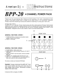
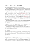
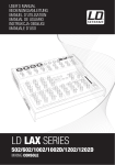
1
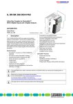
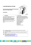
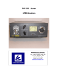
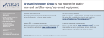
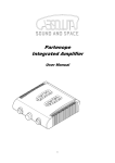
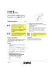
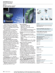
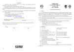
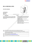
IL PB BK
PROFIBUS-DP Fieldbus Coupler
GSD
6137A001
Data Sheet 6137AC01
08/2000
This data sheet is intended to be used
in conjunction with the "Configuring
and Installing the PROFIBUS-DP
Fieldbus Coupler for the INLINE
Product Range" User Manual,
IL PB BK UM E.
Function
The PROFIBUS coupler is the link between
PROFIBUS-DP and the INTERBUS Inline
installation system.
Inline modules and INTERBUS Loop 2 modules
can be connected in any position to an existing
PROFIBUS-DP using the PROFIBUS coupler. In
this way, all the advantages of the installation
system created by this module can be used on
PROFIBUS.
Features
The PROFIBUS coupler has the following
properties:
–
A maximum of 63 Inline or Loop 2 modules
can be connected to PROFIBUS-DP by
simply plugging them in side by side via the
coupler. The coupler and the Inline modules
create a station.
–
The sum of all input and output data of the
connected modules must not exceed 192
bytes per station.
6137AC01
–
The coupler can be installed with a data
transmission speed of 9.6 kbps to 12 Mbps
The coupler is automatically set to the speed
specified by the PROFIBUS master.
–
The operating voltage of the coupler is
24 V DC. The operating temperature range
is 0°C to 55°C (32°F to 131°F).
–
Diagnostics are provided locally by LEDs on
the coupler, and on the Inline and Loop 2
modules. In addition, all diagnostic
information can be forwarded to the
PROFIBUS master via PROFIBUS.
The intelligent wiring method used in the
INTERBUS Inline and Loop 2 modules allows
the stations to be constructed easily and quickly
because, for example, there is no need for
time-consuming wiring of module power
supplies. In the simplest case, it is only
necessary for the power supply units integrated
in the PROFIBUS coupler to be supplied with
24 V DC. They then generate the operating
voltage required for the PROFIBUS coupler and
the connected Inline modules.
1
IL PB BK
GSD
6137A003
6137A002
Figure 1
IL PB BK module with connector and
end plate
Please note that the connector is not
supplied with the terminal. Refer to
Ordering Data at the end of this data
sheet to order the appropriate
connector for your application.
The end plate is supplied with the
PROFIBUS-DP Fieldbus Coupler. Place this
plate at the end of the Inline station. The end
plate does not have any electrical function. It
protects the station from ESD pulses and the
user from dangerous voltage.
2
Figure 2
Disk with device database file (GSD)
A disk is provided with the PROFIBUS-DP
Fieldbus Coupler. It contains the device
database file (GSD) required by PROFIBUS and
a bitmap file with an icon of the coupler and
connected Inline modules.
An up-to-date device database file
can be downloaded from the
InfoService on the Internet at
www.phoenixcontact.com.
6137AC01
IL PB BK
Connecting PROFIBUS
5
4
3
2
1
9
8
7
6
6137A006
Figure 3
Pin assignment of the 9-pos. D-SUB
female connector
Supplying the Operating Voltages
Terminal
Points
Remark
1.1, 2.1
Segment supply (+24 V DC)
1.2, 2.2
Main supply, fieldbus coupler
supply, communications power
and interface supply (+24 V DC)
1.3, 2.3
Reference potential
1.4, 2.4
Functional earth ground (FE)
Connect PROFIBUS to the fieldbus coupler
using a 9-pos. D-SUB connector (e.g.,
SUBCON-PLUS-PROFIB,
Order No. 27 44 34 8). Please refer to the Pin
assignment in the following table:
1
1
1
2
2
+
3
Assignment
1
Reserved
2
Reserved
3
RxD/TxD-P (+ receive/send data),
cable B
4
CNTR-P (control signal for repeater),
direction control
5
DGND (reference potential up to 5 V)
6
VP (supply voltage +5 V for terminal
resistors)
+
3
4
Pin
2
Reserved
8
RxD/TxD-N (– receive/send data),
cable B
9
Reserved
P R O F IB U S -D P
Figure 4
2 4 V
(U
S
)
)
6 1 3 7 A 0 0 7
Connection wiring plan for the
PROFIBUS coupler
Connect the fieldbus coupler according to
Figure 4. You will find the terminal point
assignment for the fieldbus coupler in Figure 5.
2
1.1
1
1
2.1
1.2
2
2
2.2
1.3
3
3
1.4
4
4
2.3
2.4
6137A008
Figure 5
6137AC01
M
4
1
7
2 4 V (U
PROFIBUS coupler power
connector
3
IL PB BK
Configure the hardware on the PROFIBUS
coupler using the 10-pos. DIP switch.
Since PROFIBUS is a serial bus system in a
star-tree structure, the individual branches must
be terminated with a terminal resistor. The
PROFIBUS coupler does not have a resistor of
this type. For additional information please refer
to your PROFIBUS documents. Phoenix
Contact recommends using the PROFIBUS
connector SUBCON-PLUS-PROFIB,
Order No. 27 44 34 8. This connector has a
terminal resistor that can be connected.
On
Line Terminal Resistors
1 2 3 4 5 6 7 8 9 10
Hardware Configuration
6137A004
Figure 6
PROFIBUS coupler DIP switches
The PROFIBUS address and other PROFIBUS
coupler settings can be set using the 10-pos.
DIP switch. The meaning of the switches is given
in the following table.
DIP Switches
Meaning
1 to 7
PROFIBUS Address in binary format (= 0 to 127 in decimal format)
Switch 1 defines the least significant bit (20) and
switch 7 defines the most significant bit (26).
8
Behavior if a data error occurs in the Inline station (local bus error):
ON = data transmission is stopped after a number of attempts.
OFF = the station constantly attempts to start data transmission.
If DIP switch 8 is in the ON position, a POWER DOWN/POWER UP must be
executed on the fieldbus coupler so that it will restart. There is no automatic
restart after the error has been removed.
9 to 10
4
Reserved, both switches must be in the OFF position.
6137AC01
IL PB BK
Local Diagnostic Indicators on the PROFIBUS Coupler
US
UM
BF
FS
FN
PB-DP
6137A005
Figure 7
Indicators on the PROFIBUS coupler
LED
Color
Meaning
State
Description of the LED States
UM
Green
UMain
ON
24 V main circuit supply present
OFF
Main circuit supply not present
ON
24 V segment circuit supply present
OFF
Segment circuit supply not present
ON
No communication on PROFIBUS
OFF
No error
ON
If FS is on, FN indicates the error type
OFF
If FS is not on, FN indicates the error number
US
BF
FS
FN
Green
Red
Red
Red
USegment
Bus
Fault
Failure
Select
Failure
Number
Flashing
OFF
6137AC01
The number of flashing pulses indicates the type of
error or the error number, depending on whether
FS is on or not
No error
5
IL PB BK
Permitted INTERBUS Inline Devices
The following table lists all modules that can currently be operated on the PROFIBUS-DP Fieldbus
Coupler, along with their order numbers and designations, as well as their most important features.
Order Designation
Order
No.
ID Code Length
IN
dec/hex dec/hex Addr.
OUT
Addr.
PCP
Reg.
Length
Error
Message
Current
Consumption
UL
UANA
Digital Inputs
IB IL 24 DI 2
27 26 20 1 190 / BE 194 / C2 2 bits
–
–
2 bits
–
35 mA
–
IB IL 24 DI 4
27 26 21 4 190 / BE 65 / 41
4 bits
–
–
4 bits
–
40 mA
–
IB IL 24 DI 8
27 26 22 7 190 / BE 129 / 81
1 byte
–
–
1 byte
–
50 mA
–
IB IL 24 DI 16
27 26 23 0 190 / BE 01 / 01
2 bytes
–
–
2 bytes
–
60 mA
–
IB IL 120 Dl 1 *)
28 36 70 6 190 / BE 194 / C2 2 bits
–
–
2 bits
–
25 mA
–
IB IL 24 DO 2-2A
27 26 24 3 189 / BD 194 / C2 –
2 bits
–
2 bits
K, O
35 mA
–
IB IL 24 DO 4
27 26 25 6 189 / BD 65 / 41
–
4 bits
–
4 bits
K, O
40 mA
–
IB IL 24 DO 8
27 26 26 9 189 / BD 129 / 81
–
1 byte
–
1 byte
K, O
60 mA
–
IB IL 24 DO 16
27 26 27 2 189 / BD 01 / 01
–
2 bytes
–
2 bytes
K, O
90 mA
–
2 bits
–
2 bits
–
60 mA
–
Digital Outputs
IB IL 24/230 DOR/1W 28 36 43 4 189 / BD 194 / C2 –
Analog Inputs
IB IL AI 2/SF
27 26 28 5 127/7F
02 / 02
4 bytes
4 bytes
–
4 bytes
L, P
38 mA
15 mA
IB IL TEMP 2 UTH
27 27 76 3 127/7F
02 / 02
4 bytes
4 bytes
–
4 bytes
D
43 mA
11 mA
IB IL TEMP 2 RTD
27 26 30 8 127/7F
02 / 02
4 bytes
4 bytes
–
4 bytes
D
43 mA
11 mA
Analog Outputs
IB IL AO 1/SF
27 26 29 8 125 / 7D 01 / 01
–
2 bytes
–
2 bytes
L
35 mA
25 mA
IB IL AO 1/U/SF
27 27 77 6 125 / 7D 01 / 01
–
2 bytes
–
2 bytes
L
35 mA
25 mA
IB IL AO 2U/B/P
27 32 73 2 91 / 5B
02 / 02
4 bytes
4 bytes
–
4 bytes
L
35 mA
28 mA
IB IL CNT
28 36 33 7 191 / BF 02 / 02
4 bytes
4 bytes
–
4 bytes
K, A
40 mA
–
IB IL SSI
28 36 34 0 191 / BF 02 / 02
4 bytes
4 bytes
–
4 bytes
K, A
110 mA
–
IB IL INC
28 36 32 4 191 / BF 02 / 02
4 bytes
4 bytes
–
4 bytes
K, A
110 mA
–
Special Function Modules
6
6137AC01
IL PB BK
Order Designation
IB IL 24 L2
Order
No.
ID Code Length
IN
dec/hex dec/hex Addr.
27 27 88 6 –
–
OUT
Addr.
PCP
Reg.
Length
Error
Message
Current
Consumption
UL
UANA
–
–
–
–
–
85 mA
–
Power Electronics
IB IL 24 TC
27 27 41 7 190 / BE 65 / 41
4 bits
---
---
4 bits
---
60 mA
---
IB IL 400 MLR 1-8A
27 27 36 5 191 / BF 129 / 81
1 byte
1 byte
---
1 byte
ST
50 mA
---
IB IL 400 ELR 1-3A
27 27 35 2 191 / BF 129 / 81
1 byte
1 byte
---
1 byte
ST
45 mA
---
IB IL 400 ELR R-3A
27 27 37 8 191 / BF 129 / 81
1 byte
1 byte
---
1 byte
ST
45 mA
---
IB IL 24 PWR IN
27 26 31 1 –
–
–
–
–
–
–
-
–
IB IL 24 PWR IN/F
27 27 90 9 –
–
–
–
–
–
–
–
–
IB IL 24 PWR IN/F-D
28 36 66 7 190 / BE 194 / C2 2 bits
–
–
2 bits
S
25 mA
–
IB IL 24 SEG
27 26 32 4 –
–
–
–
–
–
–
–
–
IB IL 24 SEG/F
27 27 74 7 –
–
–
–
–
–
–
–
–
IB IL 24 SEG/F-D
28 36 68 3 190 / BE 194 / C2 2 bits
–
–
2 bits
SP
25 mA
–
IB IL 24 SEG-ELF
27 27 78 9 190 / BE 194 / C2 2 bits
–
–
2 bits
K
30 mA
–
Supply Terminals
The abbreviations in the "Error Message"
column are explained on page 9.
Inline special function modules,
which only support the parameter
channel (PCP) and cannot be
operated via the process data
channel (presently only the
IB IL RS-232 module) are not
permitted on the fieldbus coupler.
6137AC01
7
IL PB BK
Permitted INTERBUS Loop 2 Devices
The following table lists all modules that can currently be operated on the PROFIBUS-DP Fieldbus
Coupler, along with their order numbers and designations, as well as their most important features.
Order Designation
Order
No.
ID Code
dec/hex
Length
IN
dec/hex Addr.
OUT
Addr.
PCP Reg.
Error
Length Message
Current
USL *)
Loop 2 Digital Inputs
IB L2 BOX 24 DI 4/4 M12
27 31 98 2 178 / B2
65 / 41
4 bits
–
–
4 bits
A, K, T, U 40 mA
IB L2 BOX 24 DI 4/4 M12-D
27 32 76 1 178 / B2
65 / 41
4 bits
–
–
4 bits
A, K, T, U 40 mA
IB L2 BOX 24 DI 8/4 M12
27 31 99 5 178 / B2
129 / 81
8 bits
–
–
8 bits
A, K, T, U 40 mA
IB L2 BOX 24 DO 4/4 M12 2A
27 32 34 7 177 / B1
65 / 41
–
4 bits
–
4 bits
K, T, U
40 mA
IB L2 BOX 24 DO 4/4 M12 2A-D
27 32 77 4 177 / B1
65 / 41
–
4 bits
–
4 bits
K, T, U
40 mA
27 32 00 4 179 / B3
65 / 41
2 bits
2 bits
–
4 bits
A, K, T, U 40 mA
IB L2 BOX 24 DIO 2/2/4 M12 2A-D 27 32 78 7 179 / B3
65 / 41
2 bits
2 bits
–
4 bits
A, K, T, U 40 mA
Loop 2 Digital Outputs
Loop 2 Digital Inputs and Outputs
IB L2 BOX 24 DIO 2/2/4 M12 2A
Loop 2 Analog Inputs
IB L2 BOX Al 2/2 M12
27 31 90 8 115 / 73
02 / 02
4 bytes
4 bytes
–
4 bytes
A, K, T, U 110 mA
IB L2 BOX TEMP 2/2 M12
27 31 92 4 115 / 73
02 / 02
4 bytes
4 bytes
–
4 bytes
A, H, D, K 75 mA
IB L2 BOX AO 1/2/l M12
27 31 93 7 113 / 71
01 / 01
–
2 bytes
–
2 bytes
T, U
70 mA
IB L2 BOX AO 1/2/U M12
27 31 94 0 113 / 71
01 / 01
–
2 bytes
–
2 bytes
T, U
90 mA
27 32 38 9 179 / B3
129 / 81
1 byte
1 byte
–
1 byte
M, U, T, A 40 mA
IB L2 BOX 24 PWR IN 4/4 M12
27 26 31 1 178 / B2
65 / 41
4 bits
–
–
4 bits
A, K, T, U 40 mA
IB L2 BOX 24 PWR IN 4/4 M12-D
27 32 79 0 178 / B2
65 / 41
4 bits
–
–
4 bits
A, K, T, U 40 mA
Loop 2 Analog Outputs
Loop 2 Motor Starter
IB L2 IP 500 MLR 4-6A
Loop 2 Supply
The abbreviations in the "Error Message"
column are explained on page 9.
8
*) USL: Supply voltage for Loop 2 devices:
(maximum total current at USL: 1,8 A).
6137AC01
IL PB BK
Explanation of Error Messages
Abbreviation
Meaning
K
Indicates short-circuit and overload of an output or an initiator
supply
A
Indicates failure of the Loop main power, segment voltage or
sensor supply
S
Indicates faulty fuse
O
Indicates overload of an output
P
Indicates failure of the internal supply voltage
D
Indicates open circuit in TC operation
L
Indicates breakdown or dropping of communications power UL
T
Temperature warning protocol chip
U
Loop undervoltage
H
Hardware fault
M
Motor overtemperature
ST
Indicates selftest error
6137AC01
9
IL PB BK
PROFIBUS Standard and Device-Related Diagnostics
Error Type
Meaning
1
Parameter error on PROFIBUS (SET_PRM telegram)
2
Configuration error on PROFIBUS (CHK_CFG telegram)
Detailed information about the PROFIBUS configuration error is represented by 11
different error numbers.
3
Configuration error in the INTERBUS Inline Station
Detailed information about the INTERBUS Inline station configuration error is
represented by 7 different error numbers.
4
INTERBUS error within the station
Detailed information about INTERBUS errors within the station is represented by 6
different error numbers.
5
10
Module error
6137AC01
IL PB BK
Technical Data
General Data
Order Designation PROFIBUS-DP Fieldbus Coupler
IL PB BK
Order Number PROFIBUS-DP Fieldbus Coupler
27 40 05 4
Order Designation power connector
IB IL SCN-PWR IN-CP
Order Number power connector
27 27 63 7
Housing dimensions (width x height x depth)
91 mm x 120 mm x 71.5 mm
(3.583 in. x 4.724 in. x 2.815 in.)
Weight
210 g (without connector)
Degree of protection
IP20 according to IEC 60529
Class of protection
Class 3, according to VDE 0106,
IEC 60536
System Data
Number of devices per station
63, maximum
Sum of all I/O data per station
192 bytes, maximum
Maximum fieldbus coupler current for supplying the I/
O module logic
2 A at UL
Maximum additional current for supplying the analog
terminals
0.5 A at UANA
PROFIBUS-DP Interface
Copper cable (RS-485), connected via SUB-D shield connector; supply electrically isolated,
shielding directly connected with functional earth ground.
6137AC01
11
IL PB BK
24 V Main Supply UM
Connection method
Spring-clamp terminals
Recommended cable lengths
30 m (98.425 ft.), maximum; do not route cable
through outdoor areas
Voltage continuation
Through potential routing
Nominal value
24 V DC
Tolerance
-15% / +20% (according to EN 61 13 1-2)
Ripple
±5%
Permissible range
19.2 V to 30 V (ripple included)
Minimum current consumption at nominal
voltage
0.1 A DC
(no-load operation, i.e., incoming PROFIBUS
plugged in, no Inline devices connected)
Maximum current consumption at nominal
voltage
1.25 A DC, consists of:
0.75 A DC for communications power
0.5 A DC for analog voltage supply
Safety devices
Overvoltage
Yes
Polarity reversal
Yes
Provide an external fuse for the 24 V area.
This 24 V area must be fused externally. The power supply unit must be able
to supply 4 times the nominal current of the external circuit breaker, to ensure
that it trips in the event of an error.
24 V Segment Supply US
Connection method
Spring-clamp terminals
Recommended cable lengths
30 m (98.425 ft.), maximum; do not route cable through
outdoor areas
Voltage continuation
Through potential routing
Nominal value
24 V DC
12
6137AC01
IL PB BK
24 V Segment Supply US
Tolerance
-15% / +20% (according to EN 61 13 1-2)
Ripple
±5%
Permissible range
19.2 V to 30 V (ripple included)
Current carrying capacity
8 A, maximum
Safety devices
Overvoltage
Yes
Polarity reversal
Yes
Provide an external fuse for the 24 V area.
This 24 V area must be fused externally. The power supply unit must be able
to supply 4 times the nominal current of the external circuit breaker, to ensure
that it trips in the event of an error.
Ambient Conditions
Ambient temperature (operation)
0°C to +55°C (32°F to + 131°F)
Ambient temperature (storage)
-25°C to +85°C (-13°F to + 185°F)
Humidity (operation)
75%, on average, 85%, occasionally
In the range from 0°C to +55°C (32°F to 131°F) appropriate measures against
increased humidity (> 85%) must be taken.
Humidity (storage)
75%, on average, 85%, occasionally
For a short period, slight condensation may appear on the housing if, for
example, the terminal is brought into a closed room from a vehicle.
Air pressure (operation)
80 kPa to 106 kPa
(up to 2,000 m [6562 ft.] above sea level)
Air pressure (storage/transport)
70 kPa to 106 kPa
(up to 3000 m [9483 ft.] above sea level)
6137AC01
13
IL PB BK
Conformance With EMC Directive 89/336/EEC
Noise Immunity Test According to EN 50082-2
Electrostatic discharge (ESD)
Electromagnetic fields
Fast transients (burst)
Surge voltage
EN 61000-4-2/
IEC 61000-4-2
Criterion B
EN 61000-4-3
IEC 61000-4-3
Criterion A
EN 61000-4-4/
IEC 61000-4-4
Criterion A
EN 61000-4-5/
IEC 61000-4-5
Criterion B
6 kV contact discharge
8 kV air discharge
Field strength: 10 V/m
All interfaces: 1 kV
DC supply lines:
0.5 kV / 1 kV (symmetrical/asymmetrical)
Fieldbus cable shielding 1 kV
Conducted interference
EN 61000-4-6
IEC 61000-4-6
Criterion A
Test voltage 10 V
Noise Emission Test According to EN 50081-2
Noise emission of housing
14
EN 55011
Class A
6137AC01
IL PB BK
Ordering Data
Ordering Data for Operable Inline Modules
Description
Order Designation
Order No.
PROFIBUS coupler (with end plate and disk with
GSD file)
IL PB BK
27 40 05 4
Power connector for PROFIBUS coupler,
neighboring terminal points internally jumpered
IB IL SCN-PWR IN-CP
27 27 63 7
Power terminal without fuse
IB IL 24 PWR IN
27 26 31 1
Power terminal without fuse
IB IL 120 PWR IN
27 31 70 4
Power terminal with fuse
IB IL 24 PWR IN/F
27 27 90 9
Power terminal with fuse and diagnostics
IB IL 24 PWR IN/F-D
28 36 66 7
Segment terminal without fuse
IB IL 24 SEG
27 26 32 4
Segment terminal with fuse
IB IL 24 SEG/F
27 27 74 7
Segment terminal with fuse and diagnostics
IB IL 24 SEG/F-D
28 36 68 3
Segment terminal with electronic fuse
IB IL 24 SEG-ELF
27 27 78 9
Module with two digital inputs
IB IL 24 DI 2
27 26 20 1
Module with four digital inputs
IB IL 24 DI 4
27 26 21 4
Module with 8 digital inputs
IB IL 24 DI 8
27 26 22 7
Module with 16 digital inputs
IB IL 24 DI 16
27 26 23 0
Module with one digital input
for 120 V AC signals
IB IL 120 DI 1
28 36 70 6
PROFIBUS Coupler
Supply Terminals
Digital Inputs
6137AC01
15
IL PB BK
Description
Order Designation
Order No.
Module with two digital outputs
IB IL 24 DO 2-2A
27 26 24 3
Module with four digital outputs
IB IL 24 DO 4
27 26 25 6
Module with 8 digital outputs
IB IL 24 DO 8
27 26 26 9
Module with 16 digital outputs
IB IL 24 DO 16
27 26 27 2
Module with one digital SPDT relay output,
maximum contact voltage 230 V AC
IB IL 24/230 DOR/1W
28 36 43 4
Module with one digital output
IB IL DO 1 AC
28 36 74 8
Module with two analog current or voltage inputs
IB IL AI 2/SF
27 26 28 5
Module with two analog temperature signal
inputs
IB IL Temp 2 UTH
27 27 76 3
Module for connecting two analog temperature
shunts
IB IL Temp 2 RTD
27 26 30 8
Module with one analog current or voltage output
IB IL AO 1/SF
27 26 29 8
Module with one analog voltage output
IB IL AO 1/U/SF
27 27 77 6
Module with two analog voltage outputs
IB IL AO 2U/B/P
27 32 73 2
Counter module with switching output
IB IL CNT
28 36 33 7
Positioning module for connecting absolute
encoders
IB IL SSI
28 36 34 0
Positioning module for connecting incremental
encoders
IB IL INC
28 36 32 4
INTERBUS Loop 2 branch terminal for
integrating an INTERBUS Loop 2 system in an
Inline station
IB IL 24 L2
27 27 88 6
Digital Outputs
Analog Inputs
Analog Outputs
Special Function Modules
16
6137AC01
IL PB BK
Description
Order Designation
Order No.
Thermistor terminal for protecting motors
IB IL 24 TC
27 27 41 7
Mechanical motor starter
IB IL 400 MLR 1-8A
27 27 36 5
Electronic motor starter
IB IL 400 ELR 1-3A
27 27 35 2
Electronic motor starter
IB IL 400 ELR R-3A
27 27 37 8
Power Electronics
Ordering Data for Operable Loop 2 Modules
Description
Order Designation
Order No.
Input module four digital inputs
IB L2 BOX 24 DI 4/4 M12
27 31 98 2
Input module four digital inputs *)
IB L2 BOX 24 DI 4/4 M12-D
27 32 76 1
Input module eight digital inputs
IB L2 BOX 24 DI 8/4 M12
27 31 99 5
Output module four digital inputs
IB L2 BOX 24 DO 4/4 M12 2A
27 32 34 7
Output module four digital inputs*)
IB L2 BOX 24 DO 4/4 M12 2A-D
27 32 77 4
Input/output module two digital inputs, two
digital outputs
IB L2 BOX 24 DIO 2/2/4 M12 2A
27 32 00 4
Input/output module two digital inputs, two
digital outputs *)
IB L2 BOX 24 DIO 2/2/4 M12 2A-D
27 32 78 7
Input module two analog inputs
IB L2 BOX Al 2/2 M12
27 31 90 8
Input module for detecting two analog
temperature signals
IB L2 BOX TEMP 2/2 M12
27 31 92 4
Loop 2 Digital Inputs
Loop 2 Digital Outputs
Loop 2 Digital Inputs and Outputs
Loop 2 Analog Inputs
6137AC01
17
IL PB BK
Description
Order Designation
Order No.
Analog current signal output module
IB L2 BOX AO 1/2/l M12
27 31 93 7
Analog voltage signal output module
IB L2 BOX AO 1/2/U M12
27 31 94 0
IB L2 IP 500 MLR 4-6A
27 32 38 9
Input and power module four digital inputs
IB L2 BOX 24 PWR IN 4/4 M12
27 26 31 1
Input and power module four digital inputs*)
IB L2 BOX 24 PWR IN 4/4 M12-D
27 32 79 0
Loop 2 Analog Outputs
Loop 2 Motor Starter
Motor Starter
Loop 2 Supply
*) The actuator and sensor connector is double-assigned for these modules.
The variety of Inline and Loop 2 modules that can be operated on the PROFIBUS coupler
will continue to increase. Before installing a new module that is not listed here, find out if it
can be operated on the PROFIBUS-DP Fieldbus Coupler.
Ordering Data for Accessories
Description
Order Designation
Order No.
Coding profile (100 pcs./package)
CP-MSTB see "COMBICON"
catalog
17 34 63 4
Zack "Quick" marker strips to label the terminals
ZB 6 ... see "CLIPLINE" catalog
DIN EN 50022 mounting rail, 2 meters (6.562 ft.)
NS 35/7,5, perforated
NS 35/7,5, unperforated
08 01 73 3
08 01 68 1
End clamp
CLIPFIX 35
30 22 21 8
Universal protective conductor terminal
USLKG 5
04 41 50 4
Screwdriver according to DIN 5264, blade
width 3.5 mm (0.138 in.)
SZF 1 - 0,6 x 3,5
12 04 51 7
18
6137AC01
IL PB BK
Ordering Data for Connectors *)
Description
Order Designation
Order No.
Connector set for IB IL AO1/SF
IB IL AO/CNT-PLSET
27 32 66 4
Connector for Inline modules,
2 signals, 4-wire connection method
IB IL SCN-8
27 26 33 7
Connector for Inline modules,
2 signals, 4-wire connection method, color print
IB IL SCN-8-CP
27 27 60 8
Connector for Inline modules, for signals with
shielded cables (for example, analog signals with
shield clamp)
IB IL SCN-6 SHIELD
27 26 35 3
Connector for Inline modules,
4 signals, 3-wire connection method
IB IL SCN-12
27 26 34 0
Connector for Inline input modules,
4 signals, 3-wire connection method, with color
print
IB IL SCN-12-ICP
27 27 61 1
Connector for Inline output modules,
4 signals, 3-wire connection method
IB IL SCN-12-OCP
27 27 62 4
Power connector for Inline modules,
neighboring terminal points jumpered internally
IB IL SCN-PWR IN
27 27 46 2
Power connector for Inline modules and
PROFIBUS coupler,
neighboring terminal points jumpered internally
IB IL SCN-PWR IN-CP
27 27 63 7
Labeling field, can be snapped in, 2-slot terminal,
10 pcs./package
IB IL FIELD 2
27 27 50 1
Labeling field, can be snapped in, 8-slot terminal,
10 pcs./package
IB IL FIELD 8
27 27 51 5
*) Ordering Data for 120 V AC connenctors on request
6137AC01
19
IL PB BK
Ordering Data for Interface Converters Connected in Series and SUB-D Connectors
Description
Order Designation
Order No.
T coupler for converting RS-485 PROFIBUS to
two optical fiber cables (glass fiber); 24 V DC
current consumption: 110 mA, maximum
PSM-EG-PROFIB/FO-T/G
27 61 43 1
T coupler for converting RS-485 PROFIBUS to
two optical fiber cables (HCS/polymer fiber); 24 V
DC current consumption: 110 mA, maximum
PSM-EG-PROFIB/FO-T/K
27 61 12 7
Terminal device for converting RS-485
PROFIBUS to one optical fiber cable
(glass fiber); 24 V DC current consumption:
110 mA, maximum
PSM-EG-PROFIB/FO-E/G
27 44 36 4
Terminal device for converting RS-485
PROFIBUS to one optical fiber cable
(HCS/polymer fiber); 24 V DC current
consumption: 110 mA, maximum
PSM-EG-RS485W2/FO-E/K
27 61 48 6
Repeater for electrical isolation and increases in
distance with 3-way isolation; 24 V DC current
consumption: 90 mA, approximately
PSM-ME-RS485/RS485-P
27 44 42 9
SUB-D connector, 9-pos. with two cable feeds for
PROFIBUS up to 12 Mbps (terminal resistor can
be connected using rotary switch)
SUBCON-PLUS-PROFIB
27 44 34 8
Ordering Data for Power Supplies
Description
Order Designation
Order No.
Compact power supply, primary clock,
1A
QUINT-PS-230AC/24DC/1
29 39 44 1
Compact power supply, primary clock,
1A
QUINT-PS-120AC/24DC/1
29 39 24 7
Compact power supply, primary clock,
2.5 A with filter
QUINT-PS-230AC/24DC/2,5/F
29 39 35 7
Compact power supply, primary clock,
2.5 A with filter
QUINT-PS-120AC/24DC/2,5/F
29 39 25 0
20
6137AC01
IL PB BK
Description
Order Designation
Order No.
Compact power supply, primary clock,
5 A with filter
QUINT-PS-230AC/24DC/5/F
29 39 36 0
Compact power supply, primary clock,
5 A with filter
QUINT-PS-120AC/24DC/5/F
29 39 26 3
Compact power supply, primary clock,
10 A with filter
QUINT-PS-230AC/24DC/10/F
29 39 37 3
Compact power supply, primary clock,
10 A with filter
QUINT-PS-120AC/24DC/10/F
29 39 27 6
Compact power supply, primary clock,
20 A with filter
QUINT-PS-3x400AC/24DC/20/F
29 39 56 4
Compact power supply, primary clock,
30 A with filter
QUINT-PS-3x400AC/24DC/30/F
29 39 39 9
Compact power supply, primary clock,
40 A with filter
QUINT-PS-3x400AC/24DC/40/F
29 39 94 6
Compact power supply, primary clock,
650 mA, MCR housing
MCR-PS-230AC/24DC/650
28 11 95 4
Compact power supply, primary clock,
650 mA, MCR housing
MCR-PS-120AC/24DC/650
28 11 96 7
6137AC01
21
IL PB BK
Description
Order Designation
Order No.
"Configuring and Installing the PROFIBUS-DP
Fieldbus Coupler for the Inline Product Range"
User Manual (German)
IL PB BK UM
26 98 09 6
"Configuring and Installing the PROFIBUS-DP
Fieldbus Coupler for the Inline Product Range"
User Manual (English)
IL PB BK UM E
26 98 10 6
CD-ROM with all Inline, Loop 2 and other data
sheets
CD IBS DB ELDOC
27 45 60 6
"Configuring and Installing the INTERBUS
Loop 2" User Manual (German)
IB L2 SYS PRO UM
27 43 45 9
"Configuring and Installing the INTERBUS
Loop 2" User Manual (English)
IB L2 SYS PRO UM E
27 43 49 1
All documentation is also available on the Internet at http://www.phoenixcontact.com.
Phoenix Contact GmbH & Co
Flachsmarktstr. 8
32825 Blomberg
Germany
+ 49 - 52 35 - 3 00
+ 49 - 52 35 - 34 12 00
www.phoenixcontact.com
22
6137AC01
© Phoenix Contact 08/2000 Subject to technical modification TNR 90 03 69 5
Ordering Data for Documentation