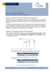
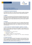
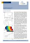
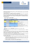
1
APPLICATION NOTE 209
STM 300 THERMO OR BATTERY POWERED –
Power Supply Alternatives to Solar Panel
Applications based on STM 300(C) in environments without enough Illumination
Alternatively to the use of a standard solar panel, e.g. in applications with no or not enough
light, the STM 300/300C module can also be powered by another suitable external power
sources like i.e. a thermo generator based on a standard Peltier (Seebeck) element and the
EnOcean ECT 300 energy harvester or even a small low cost Li/MnO2 coin battery.
Background: in sleep mode the supply current of the STM 300(C) module is typically 0.2 µA.
In operation the current consumption strongly depends on the frequency of wake ups and
radio transmissions, so the average current over time has to be considered for calculation of
the module average current consumption, see Fig.1 below, more details see chapter 2.11 of
the STM 300(C) User Manual.
100
10
Current [mA]
1
0.1
0.01
0.001
Sleep
0.0001
0.00001
0
10
20
30
40
50
60
70
80
90
100
Time [ms]
Fig.1: Current Consumption of STM 300(C)
Module Average Current Consumption and power source considerations
Calculation Example: Cyclic measurement with transmission every 100 s.
Using the table from chapter 2.11 of the STM
300(C) User Manual the required continuous supply
current depending of Wake cycles and Transmit
interval settings can be easily found.
According the mentioned table (first, second and
last column, see Table 1) a STM 300(C) needs a
1.6 µA continuous current to wake up every 100
seconds (Wake cycle=100) and transmit by every
Wake (Transmit Interval=1):
I_STM ≈ 1.6 µA
© EnOcean | www.enocean.com
Table 1
Wake
cycle
[s]
1
1
1
10
10
10
100
100
100
Transmit
interval
1
10
100
1
10
100
1
10
100
Current required
cont. operation
(µA)
130.5
40.5
31.3
13.5
4.4
3.5
1.6
0.8
0.6
Subject to modifications | Christian Bach | Feb 2010 | Page 1/ 3
APPLICATION NOTE 209
STM 300 THERMO OR BATTERY POWERED –
Power Supply Alternatives to Solar Panel
Using a Battery as power supply:
Even a small battery capacity of 0.150 Ah (a coin cell CR2032 has > 0.230 Ah) would theoretically mean about 10 years continuously function for this setting (150 mAh = 0.0016 mA x
X h => X = 150 mAh/0.0016 mA = 93750 h = 3900 days).
Bearing in mind that the energy of a battery cannot be fully
drawn for this purpose (means only approx. 50% of its
nominal capacity, until the voltage drops below about 2.2
Fig.2
V), a single CR2032 coin cell still allows more than 8 years
of continuous function. In these 8 years the STM 300(C) can wake up and transmit more than
2.5 millions times. Please notice that in order to ensure the needed peak current capability of
approx. 40 mA without damage, the coin cell battery must be buffered by an external low
leakage capacitor (not on STM 300(C) included, see Fig.2.)
For low cost applications standard manganese dioxide lithium 3 V coin battery can be used.
Depending on the energy demand different capacity sizes can be chosen. Generally please
consider the limited life time behavior of batteries, even if the energy balance calculation indicates a multiple year operation time. It also could be useful to have a control of the supply
voltage to know in time when the battery voltage fails below a certain limit to be changed
before failure. The circuitry described in the Application note AN309 can be used to do this.
Using a Thermo generator (ECT 300 + Peltier element) as power supply (Fig.3):
Considering again the Table 1 relation (same
scenario, I_STM ≈ 1.6 µA) and considering a
STM 300(C) supply voltage of 2.7 V results the
long term averaged required power at the
transmitter to send every 100 seconds:
P=U x I: or P=2.6 Vx1.6 µA=4.4 µW.
Fig.3
An ECT 300 based thermo generator
would deliver this power by >2 K
temperature difference as shown in
Fig.4 (ECT 300 User Manual):
The Peltier element output voltage,
(12.5 mV/K) is in this case only 25
mV. Considering for the ECT 300 at
this absolute lowest operational input
voltage a conversion efficiency of
20%, about 22 µW of continuous input
power (delivered by the Peltier element) are therefore required. The
energy storage device C* (Fig.3) at
the ECT 300 output has now two
Fig.4
functions: it must store the continuous
delivered low energy (i.e. 4,4 µWs)
between two consecutive transmissions (i.e. for 100 seconds) and deliver the required peak
currents.
Please note in this case that at least 2K permanent temperature difference between the both
sides of the Peltier element must be always available, otherwise the use of an appropiate energy storage management circuit is recommended, e.g. see STM 300(C) User Manual, §3.1.
For more details about specific system performance and considerations regarding thermo
generator dimensioning please consult the ECT 300 and EDK 300(C) user manuals.
© EnOcean | www.enocean.com
Subject to modifications | Christian Bach | Feb 2010 | Page 2/ 3
APPLICATION NOTE 209
STM 300 THERMO OR BATTERY POWERED –
Power Supply Alternatives to Solar Panel
Disclaimer
The information provided in this document describes typical features of the EnOcean radio system and should not be
misunderstood as specified operating characteristics. No liability is assumed for errors and / or omissions. We reserve
the right to make changes without prior notice. For the latest documentation visit the EnOcean website at
www.enocean.com.
© EnOcean | www.enocean.com
Subject to modifications | Christian Bach | Feb 2010 | Page 3/ 3