1
DAQ
NI 435x User Manual
High-Precision Temperature and Voltage Meters
NI 435x User Manual
March 2005
370841B-01
Support
Worldwide Technical Support and Product Information
ni.com
National Instruments Corporate Headquarters
11500 North Mopac Expressway
Austin, Texas 78759-3504
USA Tel: 512 683 0100
Worldwide Offices
Australia 1800 300 800, Austria 43 0 662 45 79 90 0, Belgium 32 0 2 757 00 20, Brazil 55 11 3262 3599,
Canada 800 433 3488, China 86 21 6555 7838, Czech Republic 420 224 235 774, Denmark 45 45 76 26 00,
Finland 385 0 9 725 725 11, France 33 0 1 48 14 24 24, Germany 49 0 89 741 31 30, India 91 80 51190000,
Israel 972 0 3 6393737, Italy 39 02 413091, Japan 81 3 5472 2970, Korea 82 02 3451 3400,
Lebanon 961 0 1 33 28 28, Malaysia 1800 887710, Mexico 01 800 010 0793, Netherlands 31 0 348 433 466,
New Zealand 0800 553 322, Norway 47 0 66 90 76 60, Poland 48 22 3390150, Portugal 351 210 311 210,
Russia 7 095 783 68 51, Singapore 1800 226 5886, Slovenia 386 3 425 4200, South Africa 27 0 11 805 8197,
Spain 34 91 640 0085, Sweden 46 0 8 587 895 00, Switzerland 41 56 200 51 51, Taiwan 886 02 2377 2222,
Thailand 662 992 7519, United Kingdom 44 0 1635 523545
For further support information, refer to the Technical Support and Professional Services appendix. To comment
on National Instruments documentation, refer to the National Instruments Web site at ni.com/info and enter
the info code feedback.
© 2003–2005 National Instruments Corporation. All rights reserved.
Important Information
Warranty
The NI 4350 and NI 4351 devices are warranted against defects in materials and workmanship for a period of one year from the date of
shipment, as evidenced by receipts or other documentation. National Instruments will, at its option, repair or replace equipment that proves to
be defective during the warranty period. This warranty includes parts and labor.
The media on which you receive National Instruments software are warranted not to fail to execute programming instructions, due to defects
in materials and workmanship, for a period of 90 days from date of shipment, as evidenced by receipts or other documentation. National
Instruments will, at its option, repair or replace software media that do not execute programming instructions if National Instruments receives
notice of such defects during the warranty period. National Instruments does not warrant that the operation of the software shall be
uninterrupted or error free.
A Return Material Authorization (RMA) number must be obtained from the factory and clearly marked on the outside of the package before
any equipment will be accepted for warranty work. National Instruments will pay the shipping costs of returning to the owner parts which are
covered by warranty.
National Instruments believes that the information in this document is accurate. The document has been carefully reviewed for technical
accuracy. In the event that technical or typographical errors exist, National Instruments reserves the right to make changes to subsequent
editions of this document without prior notice to holders of this edition. The reader should consult National Instruments if errors are suspected.
In no event shall National Instruments be liable for any damages arising out of or related to this document or the information contained in it.
EXCEPT AS SPECIFIED HEREIN, NATIONAL INSTRUMENTS MAKES NO WARRANTIES, EXPRESS OR IMPLIED, AND SPECIFICALLY DISCLAIMS ANY WARRANTY OF
MERCHANTABILITY OR FITNESS FOR A PARTICULAR PURPOSE. CUSTOMER’S RIGHT TO RECOVER DAMAGES CAUSED BY FAULT OR NEGLIGENCE ON THE PART OF
NATIONAL INSTRUMENTS SHALL BE LIMITED TO THE AMOUNT THERETOFORE PAID BY THE CUSTOMER. NATIONAL INSTRUMENTS WILL NOT BE LIABLE FOR
DAMAGES RESULTING FROM LOSS OF DATA, PROFITS, USE OF PRODUCTS, OR INCIDENTAL OR CONSEQUENTIAL DAMAGES, EVEN IF ADVISED OF THE POSSIBILITY
THEREOF. This limitation of the liability of National Instruments will apply regardless of the form of action, whether in contract or tort, including
negligence. Any action against National Instruments must be brought within one year after the cause of action accrues. National Instruments
shall not be liable for any delay in performance due to causes beyond its reasonable control. The warranty provided herein does not cover
damages, defects, malfunctions, or service failures caused by owner’s failure to follow the National Instruments installation, operation, or
maintenance instructions; owner’s modification of the product; owner’s abuse, misuse, or negligent acts; and power failure or surges, fire,
flood, accident, actions of third parties, or other events outside reasonable control.
Copyright
Under the copyright laws, this publication may not be reproduced or transmitted in any form, electronic or mechanical, including photocopying,
recording, storing in an information retrieval system, or translating, in whole or in part, without the prior written consent of National
Instruments Corporation.
Trademarks
National Instruments, NI, ni.com, and LabVIEW are trademarks of National Instruments Corporation. Refer to the Terms of Use section
on ni.com/legal for more information about National Instruments trademarks.
Other product and company names mentioned herein are trademarks or trade names of their respective companies.
Members of the National Instruments Alliance Partner Program are business entities independent from National Instruments and have no
agency, partnership, or joint-venture relationship with National Instruments.
Patents
For patents covering National Instruments products, refer to the appropriate location: Help»Patents in your software, the patents.txt file
on your CD, or ni.com/patents.
WARNING REGARDING USE OF NATIONAL INSTRUMENTS PRODUCTS
(1) NATIONAL INSTRUMENTS PRODUCTS ARE NOT DESIGNED WITH COMPONENTS AND TESTING FOR A LEVEL OF
RELIABILITY SUITABLE FOR USE IN OR IN CONNECTION WITH SURGICAL IMPLANTS OR AS CRITICAL COMPONENTS IN
ANY LIFE SUPPORT SYSTEMS WHOSE FAILURE TO PERFORM CAN REASONABLY BE EXPECTED TO CAUSE SIGNIFICANT
INJURY TO A HUMAN.
(2) IN ANY APPLICATION, INCLUDING THE ABOVE, RELIABILITY OF OPERATION OF THE SOFTWARE PRODUCTS CAN BE
IMPAIRED BY ADVERSE FACTORS, INCLUDING BUT NOT LIMITED TO FLUCTUATIONS IN ELECTRICAL POWER SUPPLY,
COMPUTER HARDWARE MALFUNCTIONS, COMPUTER OPERATING SYSTEM SOFTWARE FITNESS, FITNESS OF COMPILERS
AND DEVELOPMENT SOFTWARE USED TO DEVELOP AN APPLICATION, INSTALLATION ERRORS, SOFTWARE AND
HARDWARE COMPATIBILITY PROBLEMS, MALFUNCTIONS OR FAILURES OF ELECTRONIC MONITORING OR CONTROL
DEVICES, TRANSIENT FAILURES OF ELECTRONIC SYSTEMS (HARDWARE AND/OR SOFTWARE), UNANTICIPATED USES OR
MISUSES, OR ERRORS ON THE PART OF THE USER OR APPLICATIONS DESIGNER (ADVERSE FACTORS SUCH AS THESE ARE
HEREAFTER COLLECTIVELY TERMED “SYSTEM FAILURES”). ANY APPLICATION WHERE A SYSTEM FAILURE WOULD
CREATE A RISK OF HARM TO PROPERTY OR PERSONS (INCLUDING THE RISK OF BODILY INJURY AND DEATH) SHOULD
NOT BE RELIANT SOLELY UPON ONE FORM OF ELECTRONIC SYSTEM DUE TO THE RISK OF SYSTEM FAILURE. TO AVOID
DAMAGE, INJURY, OR DEATH, THE USER OR APPLICATION DESIGNER MUST TAKE REASONABLY PRUDENT STEPS TO
PROTECT AGAINST SYSTEM FAILURES, INCLUDING BUT NOT LIMITED TO BACK-UP OR SHUT DOWN MECHANISMS.
BECAUSE EACH END-USER SYSTEM IS CUSTOMIZED AND DIFFERS FROM NATIONAL INSTRUMENTS' TESTING
PLATFORMS AND BECAUSE A USER OR APPLICATION DESIGNER MAY USE NATIONAL INSTRUMENTS PRODUCTS IN
COMBINATION WITH OTHER PRODUCTS IN A MANNER NOT EVALUATED OR CONTEMPLATED BY NATIONAL
INSTRUMENTS, THE USER OR APPLICATION DESIGNER IS ULTIMATELY RESPONSIBLE FOR VERIFYING AND VALIDATING
THE SUITABILITY OF NATIONAL INSTRUMENTS PRODUCTS WHENEVER NATIONAL INSTRUMENTS PRODUCTS ARE
INCORPORATED IN A SYSTEM OR APPLICATION, INCLUDING, WITHOUT LIMITATION, THE APPROPRIATE DESIGN,
PROCESS AND SAFETY LEVEL OF SUCH SYSTEM OR APPLICATION.
Compliance
Compliance with FCC/Canada Radio Frequency Interference
Regulations
Determining FCC Class
The Federal Communications Commission (FCC) has rules to protect wireless communications from interference. The FCC
places digital electronics into two classes. These classes are known as Class A (for use in industrial-commercial locations only)
or Class B (for use in residential or commercial locations). All National Instruments (NI) products are FCC Class A products.
Depending on where it is operated, this Class A product could be subject to restrictions in the FCC rules. (In Canada, the
Department of Communications (DOC), of Industry Canada, regulates wireless interference in much the same way.) Digital
electronics emit weak signals during normal operation that can affect radio, television, or other wireless products.
All Class A products display a simple warning statement of one paragraph in length regarding interference and undesired
operation. The FCC rules have restrictions regarding the locations where FCC Class A products can be operated.
Consult the FCC Web site at www.fcc.gov for more information.
FCC/DOC Warnings
This equipment generates and uses radio frequency energy and, if not installed and used in strict accordance with the instructions
in this manual and the CE marking Declaration of Conformity*, may cause interference to radio and television reception.
Classification requirements are the same for the Federal Communications Commission (FCC) and the Canadian Department
of Communications (DOC).
Changes or modifications not expressly approved by NI could void the user’s authority to operate the equipment under the
FCC Rules.
Class A
Federal Communications Commission
This equipment has been tested and found to comply with the limits for a Class A digital device, pursuant to part 15 of the FCC
Rules. These limits are designed to provide reasonable protection against harmful interference when the equipment is operated
in a commercial environment. This equipment generates, uses, and can radiate radio frequency energy and, if not installed and
used in accordance with the instruction manual, may cause harmful interference to radio communications. Operation of this
equipment in a residential area is likely to cause harmful interference in which case the user is required to correct the interference
at their own expense.
Canadian Department of Communications
This Class A digital apparatus meets all requirements of the Canadian Interference-Causing Equipment Regulations.
Cet appareil numérique de la classe A respecte toutes les exigences du Règlement sur le matériel brouilleur du Canada.
Compliance with EU Directives
Users in the European Union (EU) should refer to the Declaration of Conformity (DoC) for information* pertaining to the
CE marking. Refer to the Declaration of Conformity (DoC) for this product for any additional regulatory compliance
information. To obtain the DoC for this product, visit ni.com/certification, search by model number or product line,
and click the appropriate link in the Certification column.
* The CE marking Declaration of Conformity contains important supplementary information and instructions for the user or
installer.
Contents
About This Manual
Conventions ...................................................................................................................ix
Related Documentation..................................................................................................x
Examples........................................................................................................................x
Chapter 1
Introduction
About the NI 435x High-Precision DAQ Devices ........................................................1-1
Using PXI with CompactPCI ........................................................................................1-2
Configuration .................................................................................................................1-2
Software Options for the NI 435x..................................................................................1-2
What Is the NI-435x Instrument Driver?.........................................................1-2
What Is LabVIEW? .........................................................................................1-3
What Is LabWindows/CVI? ............................................................................1-3
What Is VI Logger? .........................................................................................1-3
Installing the Software ...................................................................................................1-3
Installing the Hardware..................................................................................................1-4
NI PXI-4351 ....................................................................................................1-4
NI PCI-4351 ....................................................................................................1-5
NI USB-4350...................................................................................................1-6
Power Considerations .......................................................................1-6
LED Patterns .....................................................................................1-7
Safety .............................................................................................................................1-8
Configuring the Hardware in MAX...............................................................................1-8
Creating a Task in VI Logger ........................................................................................1-9
Using Virtual Channels with VI Logger .........................................................1-9
Creating Virtual Channels.................................................................1-9
Modifying Virtual Channels .............................................................1-9
Testing Virtual Channels ..................................................................1-10
Creating and Configuring a Task ....................................................................1-10
Selecting Channels for a VI Logger Task to Acquire and
Log Data.........................................................................................1-11
Configuring Events for a Logging Task ...........................................1-12
Creating Calculated Channels...........................................................1-12
Accessories ....................................................................................................................1-13
© National Instruments Corporation
v
NI 435x User Manual
Contents
Chapter 2
Operating the NI 435x Device
Warming up the NI 435x Device................................................................................... 2-1
Choosing a Measurement Mode.................................................................................... 2-1
Available Ranges .......................................................................................................... 2-2
Choosing a Reading Rate .............................................................................................. 2-2
Knowing the Signal Source ........................................................................................... 2-4
Floating Signal Source .................................................................................... 2-4
Ground-Referenced Signal Source ................................................................. 2-4
Using Programmable Ground-Referencing .................................................................. 2-5
Using Programmable Open-Thermocouple Detection ................................................. 2-5
Measuring Temperature with Thermocouples............................................................... 2-6
Connecting the Thermocouple ....................................................................... 2-8
Input Ranges .................................................................................................. 2-8
Optimizing Measurements ............................................................................. 2-8
Auto Zero ......................................................................................... 2-9
Programmable Ground-Referencing ................................................ 2-9
Programmable Open-Thermocouple Detection ............................... 2-10
AC Noise Effects ............................................................................. 2-10
Thermal EMF .................................................................................. 2-11
Measuring DC Voltage.................................................................................................. 2-11
Connecting the DC Voltage Signal ................................................................. 2-11
Input Ranges ................................................................................................... 2-11
Optimizing Measurements .............................................................................. 2-12
Auto Zero ......................................................................................... 2-12
Programmable Ground-Referencing ................................................ 2-12
Programmable Open-Thermocouple Detection ............................... 2-12
Source Impedance ............................................................................ 2-13
AC Noise Effects ............................................................................. 2-13
Thermal EMF .................................................................................. 2-13
Measuring Resistance and Measuring Temperature with RTDs and Thermistors........ 2-13
Using the Current Source ................................................................................ 2-14
Connecting Resistors....................................................................................... 2-14
Input Ranges .................................................................................................. 2-16
Introduction to RTDs ...................................................................................... 2-20
Relationship of Resistance and Temperature in RTDs .................... 2-20
Connecting the RTD ....................................................................................... 2-22
Introduction to Thermistors ............................................................................ 2-23
Resistance-Temperature Characteristic of Thermistors ................... 2-24
Connecting the Thermistor ............................................................................. 2-25
NI 435x User Manual
vi
ni.com
Contents
Optimizing Measurements ..............................................................................2-25
Auto Zero .........................................................................................2-25
Programmable Ground-Referencing ................................................2-26
Programmable Open-Thermocouple Detection ...............................2-26
Connecting to External Circuits .......................................................2-26
2-Wire, 3-Wire, and 4-Wire Measurements .....................................2-26
Self-Heating .....................................................................................2-27
AC Noise Effects .............................................................................2-27
Thermal EMF ...................................................................................2-28
Using Digital Inputs and Outputs ..................................................................................2-28
Connecting the Digital Input and Output ........................................................2-29
Appendix A
Specifications
Appendix B
Signal Connections
Appendix C
Technical Support and Professional Services
Glossary
Index
© National Instruments Corporation
vii
NI 435x User Manual
About This Manual
This manual describes the National Instruments 4350/4351 devices and
contains information concerning device operation and programming.
Conventions
The following conventions appear in this manual:
<>
Angle brackets that contain numbers separated by an ellipsis represent
a range of values associated with a bit or signal name—for example,
DIO<3..0>.
»
The » symbol leads you through nested menu items and dialog box options
to a final action. The sequence File»Page Setup»Options directs you to
pull down the File menu, select the Page Setup item, and select Options
from the last dialog box.
♦
The ♦ symbol indicates that the following text applies only to a specific
product, a specific operating system, or a specific software version.
This icon denotes a note, which alerts you to important information.
This icon denotes a caution, which advises you of precautions to take to
avoid injury, data loss, or a system crash. When this symbol is marked on
the product, refer to the Read Me First: Safety and Radio-Frequency
Interference document, shipped with the product, for precautions to take.
This icon denotes a tip, which alerts you to advisory information.
bold
Bold text denotes items that you must select or click in the software, such
as menu items and dialog box options. Bold text also denotes parameter
names.
italic
Italic text denotes variables, emphasis, a cross reference, or an introduction
to a key concept. This font also denotes text that is a placeholder for a word
or value that you must supply.
monospace
Text in this font denotes text or characters that you should enter from the
keyboard, sections of code, programming examples, and syntax examples.
This font is also used for the proper names of disk drives, paths, directories,
programs, subprograms, subroutines, device names, functions, operations,
variables, filenames, and extensions.
© National Instruments Corporation
ix
NI 435x User Manual
About This Manual
NI 435x
Refers to all NI 4350 and NI 4351 devices.
NI 435x for PXI,
PCI, and USB
Refers to the NI 4350 and NI 4351 devices by form factor.
NI PCI-4351
Refers to the NI 4351 for PCI.
NI PXI-4351
Refers to the NI 4351 for PXI.
NI USB-4350
Refers to the NI 4350 for USB. Software sometimes refers to this device as
the NI DAQPad-4350.
Related Documentation
This manual is one piece of the NI 435x documentation set. Refer to the
following documents at ni.com/manuals for additional information that
is relevant to the NI 435x devices.
•
Read Me First: Safety and Radio-Frequency Interference
•
Refer to the following software documentation at Start»Programs»
National Instruments»NI-435x»Documentation:
•
–
NI 435x LabVIEW Reference Help
–
NI 435x C/C++/CVI/VB Help
Accessory installation guides or manuals—If you are using accessory
products, read the terminal block, adapter, and cable assembly
installation guides. They explain how to physically connect the
relevant pieces of the system. Consult these guides when you are
making connections.
Examples
Complete the following steps to refer to the NI 435x examples through the
NI Example Finder in LabVIEW:
NI 435x User Manual
1.
Launch LabVIEW.
2.
Select Open.
3.
Select Examples.
4.
Enter a keyword to search all available examples.
x
ni.com
1
Introduction
This chapter describes the NI 435x high-precision temperature and voltage
meters and describes the optional software and equipment.
About the NI 435x High-Precision DAQ Devices
The NI 435x devices for PXI, PCI, and USB feature accurate thermocouple
and DC voltage meters. You also can take temperature measurements with
resistance temperature detectors (RTDs) or thermistors, resistance
measurements using built-in precision current sources, and current
measurements using external shunt resistors. The NI 435x hardware is
plug-and-play compatible, fully software calibrated, and compatible with a
variety of operating systems.
NI 435x hardware has a 24-bit sigma-delta analog-to-digital converter
(ADC) with differential analog inputs. The low-leakage construction and
analog and digital filtering provide excellent resolution, accuracy, and
noise rejection. Software-programmable ground-referencing enables you
to reference a floating signal without compromising voltage measurements
even if the floating signal is ground-referenced. Software-programmable
open-thermocouple detection allows you to detect a broken thermocouple.
You can measure resistance up to 600 kΩ using the built-in 25 µΑ precision
current source on all NI 435x hardware, and up to 15 kΩ with the additional
built-in 1 mA precision current source on the NI PXI/PCI-4351. Also,
programmable TTL-compatible digital I/O (DIO) lines monitor TTL-level
inputs, interface with external devices, and generate alarms.
A system based upon NI 435x hardware offers flexibility, performance, and
compact size, making it ideal for service, repair, and manufacturing, and for
use in industrial and laboratory environments.
Detailed specifications for the NI 435x devices are in Appendix A,
Specifications.
© National Instruments Corporation
1-1
NI 435x User Manual
Chapter 1
Introduction
Using PXI with CompactPCI
Using PXI-compatible products with standard CompactPCI products is an
important feature provided by the PXI Specification. Refer to
www.pxisa.org for more information.
The NI PXI-4351 does not have connections to reserved lines on the
CompactPCI J2 connector. Therefore, you can use the NI PXI-4351
in a CompactPCI system that uses J2 connector lines for purposes other
than PXI.
Configuration
The NI 435x is a completely software-configurable, plug-and-play
instrument. The plug-and-play services query the instrument and allocate
the required resources, and the operating system then enables the
instrument for operation.
Software Options for the NI 435x
You can use LabVIEW, LabWindows™/CVI™, Microsoft Visual Basic,
C/C++, or VI Logger to program and use the NI 435x. This section
provides details on the software choices available for the NI 435x.
What Is the NI-435x Instrument Driver?
An instrument driver packages instrument capabilities as a set of standard
functions. Each function corresponds to a programmatic operation such as
configuring, reading from, writing to, and starting and stopping
measurements. An instrument driver reduces the program development
time and simplifies instrument control by eliminating the need to learn
complex programming protocol for each instrument.
The NI-435x instrument driver provides programmability in a standard
instrument driver format. The instrument driver application programming
interface (API) was designed after a traditional, full-featured data logger
instrument driver. The NI-435x instrument driver is VXI plug-and-play
compatible and also contains the source code, so you can examine and
modify it. The NI-435x instrument driver works with LabVIEW,
LabWindows/CVI, or conventional programming languages such as C,
C++, and Visual Basic. Refer to the NI 435x LabVIEW Reference Help and
the NI 435x C/C++/CVI/VB Help at Start»Programs»National
Instruments»NI-435x»Documentation.
NI 435x User Manual
1-2
ni.com
Chapter 1
Introduction
What Is LabVIEW?
LabVIEW is a powerful graphical programming language for building
instrumentation systems featuring interactive graphics and state-of-the-art
user interface. With LabVIEW, you can quickly create front panel user
interfaces, giving you interactive control of the software system. To specify
the functionality, you intuitively assemble block diagrams—a natural
design notation for engineers and scientists. LabVIEW has all of the same
development tools and language capabilities of a standard language such as
C—looping and Case structures, configuration management tools, and
compiled performance.
Use the NI-435x instrument driver VIs with LabVIEW.
What Is LabWindows/CVI?
LabWindows/CVI is an interactive ANSI C programming environment
designed for automated test applications. LabWindows/CVI enhances
traditional programming languages.
Use the NI-435x instrument driver functions with LabWindows/CVI.
What Is VI Logger?
VI Logger equips you with the necessary software tools to define and
execute a data logging task. With VI Logger, you can view real-time data,
share data, and browse and manage historical data. Using VI Logger in
Measurement & Automation Explorer (MAX) with such features as event
detection and calculated channels, you can define advanced tasks without
any programming. Using LabVIEW and the VI Logger VIs, you can
execute a task, view live data, browse historical data, and build logging
applications using all of the advanced programming capabilities of
LabVIEW.
Refer to the Creating a Task in VI Logger section of this manual for
information on using VI Logger.
Installing the Software
Refer to the NI 435x Getting Started Guide that ships with the NI 435x
hardware or at ni.com/manuals for information about installing NI-435x
instrument driver software and VI Logger software.
© National Instruments Corporation
1-3
NI 435x User Manual
Chapter 1
Introduction
Installing the Hardware
To install the NI PXI-4351, NI PCI-4351, or NI USB-4350 hardware,
complete the steps of the appropriate procedure as follows.
Cautions Follow proper ESD precautions to ensure you are grounded before installing the
hardware. Refer to Appendix A, Specifications, for important safety and compliance
information.
For safety information that is relevant to the NI 435x devices, refer to the Read Me First:
Safety and Radio-Frequency Interference document in the NI 435x shipping kit or at
ni.com/manuals.
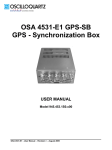
NI PXI-4351
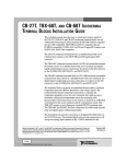
Complete the following steps and refer to Figure 1-1 to install the
NI PXI-4351.
1
7
PX
I-1
000
B
2
3
6
5
4
1
2
3
4
PXI Chassis
PXI System Controller
NI PXI-4351
Injector/Ejector Handle
5
6
7
Front-Panel Mounting Screws
Module Guides
Power Switch
Figure 1-1. Installing the NI PXI-4351
1.
NI 435x User Manual
Power off and unplug the PXI chassis.
1-4
ni.com
Chapter 1
Introduction
Before removing equipment covers or connecting or disconnecting any signal
wires, refer to the Read Me First: Safety and Radio-Frequency Interference document in
the NI PXI-4351 shipping kit or at ni.com/manuals.
Caution
2.
Remove the filler panel from an unused PXI slot.
3.
Touch any metal part of the chassis to discharge static electricity.
4.
Ensure that the injector/ejector handle on the NI PXI-4351 is not
latched and swings freely.
5.
Place the NI PXI-4351 edges into the device guides at the top and
bottom of the chassis.
6.
Slide the NI PXI-4351 into the PXI slot to the rear of the chassis.
7.
When you begin to feel resistance, pull up on the injector/ejector
handle to fully insert the NI PXI-4351.
8.
Secure the NI PXI-4351 to the chassis front panel mounting rail using
the front-panel mounting screws.
9.
Plug in and power on the PXI chassis.
NI PCI-4351
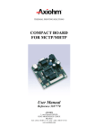
Complete the following steps and refer to Figure 1-2 to install the
NI PCI-4351:
1
1
NI PCI-4351
2
2
PCI Slot
Figure 1-2. Installing the NI PCI-4351
1.
© National Instruments Corporation
Power off and unplug the computer.
1-5
NI 435x User Manual
Chapter 1
Introduction
Before removing equipment covers or connecting or disconnecting any signal
wires, refer to the Read Me First: Safety and Radio-Frequency Interference document in
the NI PCI-4351 shipping kit or at ni.com/manuals.
Caution
2.
Remove the computer cover and/or the expansion slot cover.
3.
Touch any metal part of the computer to discharge static electricity.
4.
Insert the device into a PCI slot. Gently rock the device into place.
Do not force the NI PCI-4351 into place.
5.
Secure the device mounting bracket to the computer back panel rail.
6.
Replace the computer cover, if applicable.
7.
Plug in and power on the computer.
NI USB-4350
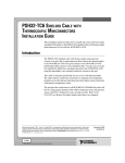
To install the NI USB-4350, connect the cable from the computer USB port
to an available USB port on the NI USB-4350. Figure 1-3 shows the
USB cable and its connectors.
2
1
1
Connector to the Computer or USB Hub
2
Connector to the NI USB-4350
Figure 1-3. USB Cable and Connectors
When you connect the NI USB-4350 to the PC, the computer recognizes
the NI USB-4350 immediately, and the LED on the device front panel
blinks or lights up, depending upon the status of the NI USB-4350.
Power Considerations
The NI USB-4350 is powered on only when the USB cable connects the
NI USB-4350 to the host PC, and the PC is powered on. The NI USB-4350
is designed to run in a stand-alone mode, drawing power only from the
USB cable. At times, the NI USB-4350 may require more power than the
USB power supply can safely deliver. If the NI USB-4350 tries to draw
more than the allowed current from the USB power supply, internal
protection circuitry turns off most of the circuitry in the NI USB-4350 to
NI 435x User Manual
1-6
ni.com
Chapter 1
Introduction
protect the USB power supply. This over-current condition makes the LED
blink in the power supply overload pattern described in the LED Patterns
section.
When the NI USB-4350 powers off, any data acquisition in progress is aborted and
the data is lost.
Note
The host computer has the ability to go into a power-saving suspend mode
and, during this time, the NI USB-4350 also can either go into a low-power
mode or remain in a fully-powered, static state. This low-power mode is
important if you are using a laptop or if power consumption is a concern.
In the powered, static state of the NI USB-4350, all digital outputs are static
at a fixed voltage.
By default, the NI USB-4350 remains fully powered during suspend mode.
To change the settings that determine the behavior of the NI USB-4350 during suspend
mode, refer to one of the following locations:
Note
•
The Set_DAQ_Device_Info section of the Traditional NI-DAQ (Legacy) Function
Reference Help, located at Start»Programs»National Instruments»NI-DAQ»
Traditional NI-DAQ (Legacy) Function Reference Help.
•
The Set DAQ Device Information (Device Setting VI) section of the LabVIEW Help,
located at Start»Programs»National Instruments»LabVIEW 7.x»VI, Function, &
How-To Help.
LED Patterns
If the LED comes on after the NI USB-4350 is connected to the computer,
the device is functioning properly. If the LED remains off or blinks, refer
to Table 1-1.
Table 1-1. LED State Patterns for the NI USB-4350 States1
LED
State
Description
On
Configured state
The NI USB-4350 is configured.
Off
Off or in the low-power,
suspend mode
The NI USB-4350 is powered off or is in the low-power, suspend mode.
1 blink
Attached state
The NI USB-4350 is recognized but not configured.
2 blinks
Addressed state
The host computer detects the NI USB-4350 but cannot configure it,
because the device driver is improperly installed or system resources are
unavailable. Check the software installation.
© National Instruments Corporation
1-7
NI 435x User Manual
Chapter 1
Introduction
Table 1-1. LED State Patterns for the NI USB-4350 States1 (Continued)
LED
State
Description
3 blinks
Power supply failure
The internal power supply shut down. Refer to the Power Considerations
section for more information.
4 blinks
General error state
Contact NI. Refer to Appendix C, Technical Support and Professional
Services, for contact information.
1
The LED blinks in one-second intervals during each cycle. The LED then waits three seconds before repeating the cycle.
Safety
For safety information that is relevant to the NI 435x devices, refer to the
Read Me First: Safety and Radio-Frequency Interference document in the
NI 435x shipping kit or at ni.com/manuals.
Configuring the Hardware in MAX
To configure the NI 435x hardware in MAX, complete the following steps:
1.
Double-click the Measurement & Automation icon on the desktop to
open MAX.
2.
Expand Devices and Interfaces.
3.
Expand Traditional NI-DAQ (Legacy) Devices.
4.
Verify that the NI 435x device name appears under Traditional
NI-DAQ (Legacy) Devices.
5.
If the NI 435x device name does not appear, press <F5> to refresh the
view in MAX. If the device is still not recognized, refer to
ni.com/support/install for troubleshooting information.
6.
Right-click the NI 435x device name and select Properties to open the
Configuring Device window. Configure the device properties,
including accessories in the Accessory tab.
7.
Click Apply to accept the changes.
8.
Click Test Resources in the System tab of the Configuring Device
window.
9.
When the self-test finishes, a message indicates successful verification
or if an error occurred. If an error occurs, refer to ni.com/support/
install for troubleshooting information.
10. Click OK to close the Configuring Device window.
NI 435x User Manual
1-8
ni.com
Chapter 1
Introduction
Creating a Task in VI Logger
This section explains how to configure and run a task using VI Logger with
the NI 435x hardware and how to view or export the resulting data.
Caution To use VI Logger with the NI 435x devices, you must activate VI Logger.
Refer to ni.com/license to activate VI Logger.
Before you create a VI Logger task, you should confirm that you have
properly configured the NI 435x hardware and associated accessories (if
applicable) as outlined in Configuring the Hardware in MAX.
Using Virtual Channels with VI Logger
Before you create a VI Logger task for an NI-DAQ traditional virtual
channel, you need to first create the virtual channel and test it.
Creating Virtual Channels
Complete the following steps to create the traditional virtual channels to
use in a data logging task.
1.
Launch the Measurement & Automation icon.
2.
In the MAX configuration tree, right-click Data Neighborhood and
select Create New from the pop-up menu.
3.
The Create New wizard opens. Select Traditional NI-DAQ (Legacy)
Virtual Channel and follow the wizard instructions to create a new
virtual channel.
Modifying Virtual Channels
Complete the following steps to modify a virtual channel.
1.
In the configuration tree of MAX, right-click a virtual channel under
Data Neighborhood.
2.
Select Properties.
3.
Make any modifications necessary in the Configuration dialog box
that appears.
4.
Click OK when you are finished.
Click the Advanced... button to view and change additional channel properties,
including Auto-zero Mode, Notch Filter Frequency, Open Thermocouple Detection, and
Ground Referencing.
Note
© National Instruments Corporation
1-9
NI 435x User Manual
Chapter 1
Introduction
Testing Virtual Channels
The Virtual Channel Test Panels show actual readings so you can directly
control the different channels you have configured. Complete the following
steps to test the virtual channels.
1.
In the configuration tree of MAX, right-click a virtual channel under
Data Neighborhood.
2.
Select Test.
3.
View the readings and change any parameters in the Virtual Channel
Test Panels dialog box.
4.
Click Close when you are finished.
Creating and Configuring a Task
When you configure a logging task, VI Logger provides feedback if any
choices you make are invalid. Complete the following steps to create a data
logging task.
1.
Launch VI Logger by selecting Start»Programs»National
Instruments»VI Logger»VI Logger in MAX.
2.
In the configuration tree in MAX, right-click VI Logger Tasks and
select Create New. The Create New dialog box appears.
3.
Select Using Traditional NI-DAQ (Legacy) and click Finish. In the
MAX configuration tree, the newly created task is selected and the
Task Attributes view is selected.
If you can only use NI-DAQmx rather than Traditional NI-DAQ (Legacy), you must
still activate the VI Logger license. Refer to ni.com/license for more information.
Note
VI Logger automatically gives the task a unique default name, which
appears under VI Logger Tasks. You can rename the task by
right-clicking on the task name and selecting Rename Task.
4.
5.
NI 435x User Manual
In the Acquisition Settings section, enter the following fields:
a.
In the Device field, select the device you are using.
b.
Select Filter Frequency. Refer to Table 2-1, Filtering and Sample
Rates, to determine the reading rate.
In the Buffer Settings section, you can define buffering parameters for
the task. With these parameters, you can modify the performance of
VI Logger, specifically if you are trying to log data at a high rate.
1-10
ni.com
Chapter 1
Introduction
You cannot log data from more than one NI-DAQ device per task. However, you can
define one task for each device and can run more than one task at the same time.
Tip
6.
In the Logging Conditions section, you can control datalogging using
one of the digital lines. Refer to the Using Digital Lines to Control
Datalogging section of the VI Logger Help by selecting Help»
Help Topics»VI Logger»VI Logger in MAX.
The NI 435x hardware does not support digital or analog triggering. By default, the
Start acquisition on trigger checkbox is unchecked. If you select the checkbox, you
receive an error when you start the task; this error indicates that triggering is not supported.
Refer to step 6 above for alternative software triggering.
Note
Selecting Channels for a VI Logger Task to Acquire
and Log Data
For each VI Logger task you configure, you can select which specific
channels acquire and log data within that task.
Complete the following steps to set up the channels that acquire and
log data.
1.
With a VI Logger Task selected, click the Virtual Channels tab to
open the Virtual Channels view.
2.
Right-click the Events column heading and select Events to enable or
disable the information displayed in the table. Refer to the
Measurement & Automation Explorer Help for VI Logger by selecting
Help»Help Topics»VI Logger»VI Logger for more information
about the information columns in the Virtual Channels view.
3.
The Active Channel column displays all the virtual channels you have
created in MAX for your device. To enable logging for each channel,
place a checkmark in the Log Enabled? checkbox to the right of each
channel name.
To add a virtual channel, click Create channel and follow the instructions in the
Create New Channel wizard.
Tip
Refer to the Creating Calculated Channels section for information about
creating calculated channels for VI Logger tasks.
© National Instruments Corporation
1-11
NI 435x User Manual
Chapter 1
Introduction
Configuring Events for a Logging Task
You can configure events to be logged in your task that will appear in the
Events view. Complete the following steps to configure the events for a
logging task.
1.
In the NI-DAQ Channels view, right-click the Channels column and
select Events.
2.
Check and uncheck the desired events to select which events to display
for the channels.
3.
You also can right-click the table cells to access more options
to modify these conditions.
Creating Calculated Channels
You can set up mathematical equations that use virtual channels using math
channels. For example, for channels Channel 0 and Channel 1, you could
enter the equation Channel 0 - Channel 1, to subtract one from the
other. The result would be a calculated channel.
Complete the following steps to create a calculated channel.
1.
Click the Calculated Channels tab to display the Calculated
Channels view.
2.
Click Create channel. The Math Expression Editor dialog box
appears where you can define a math channel.
3.
In the Channel Settings section in the Name field, enter an
appropriate name for the math channel.
4.
In the Units field, enter the appropriate unit type.
5.
In the Minimum and Maximum fields, enter a range of units that
applies to the math channel.
6.
In the Formula Settings section in the Formula field, click the down
arrow, and select one of four formulas to apply to the math channel:
7.
NI 435x User Manual
•
Ax (Op) By + C—A linear combination formula. Fill in fields A,
Channel X, Operation, B, Channel Y, and C with the
appropriate values.
•
db x/y—A measurement of noise (db)–power base 10. Select the
channels you want for Channel X and Channel Y fields.
•
dBVx—A single channel noise measurement. Select the channel
you want for the Channel X field.
•
User Defined—A formula that you create.
Click OK.
1-12
ni.com
Chapter 1
Introduction
Accessories
NI offers a variety of products to use with the NI 435x, including cables,
connector blocks, terminal blocks, and other accessories, as follows:
•
Isothermal terminal blocks—TBX-68T, CB-68T, and TC-2190
•
Terminal blocks—TBX-68
•
Shielded and ribbon cables
For more information about these products, contact NI or search for
NI PXI-4351, NI PCI-4351, or NI USB-4350 at ni.com/catalog.
© National Instruments Corporation
1-13
NI 435x User Manual
Operating the NI 435x Device
2
This chapter describes how to use the NI 435x device and includes
operation tips on taking measurements with temperature sensors such as
thermocouples, RTDs, and thermistors, as well as measuring voltages and
resistances.
Caution Refer to the Read Me First: Safety and Radio-Frequency Interference document
before removing equipment covers or connecting/disconnecting any signal wires.
Warming up the NI 435x Device
To minimize the effects of thermal drift and to ensure the specified
accuracy, allow the NI 435x device to warm up for at least 10 minutes after
startup before taking measurements. To maximize the relative accuracy of
measurements, take all measurements after the NI 435x device warms up
for 30 minutes.
Choosing a Measurement Mode
You can configure the analog input channels for measuring outputs of
various transducers, as follows:
•
Voltage
•
Thermocouples
•
Resistors
•
RTDs
When you are using Traditional NI-DAQ (Legacy) virtual channels in VI Logger,
the measurement mode is chosen by the specified sensor type.
Note
© National Instruments Corporation
2-1
NI 435x User Manual
Chapter 2
Operating the NI 435x Device
Available Ranges
The volts mode has six bipolar input ranges: ±625 mV, ±1.25 V, ±2.5 V,
±3.75 V, ±7.5 V, and ±15 V.
The resistance mode has six corresponding input ranges when used with the
built-in 25 µΑ current source on the NI PXI-4351, NI PCI-4351, and
NI USB-4350: 25 kΩ, 50 kΩ, 100 kΩ, 150 kΩ, 300 kΩ, and 600 kΩ.
With the additional built-in 1 mA current source on the NI PXI-4351 or
NI PCI-4351, resistance mode also has 625 Ω, 1.2 kΩ, 3.75 kΩ, 7.5 kΩ,
and 15 kΩ as possible input ranges.
For the best measurement results, specify the upper and lower limit values
of the measurement when configuring the NI 435x. When scanning
multiple channels, the NI 435x uses a single range, which is the widest
range of any channel in the scan list.
Specify the limit values in engineering units appropriate to the sensor. This sensor
range is used to automatically set the actual hardware range.
Note
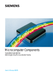
Choosing a Reading Rate
The reading rate is the rate at which the NI 435x takes a new measurement.
This rate has a direct relationship with the digital filter built into the ADC
on the NI 435x.
The digital filter has the characteristics shown in Figure 2-1. You can set the
frequency of the first notch of this filter to 10 Hz, 50 Hz, or 60 Hz. Setting
the notch filter at one of these frequencies rejects any noise at that
frequency as well as at all of its multiples.
NI 435x User Manual
2-2
ni.com
Chapter 2
Operating the NI 435x Device
0
Gain (dB)
–20
–40
–60
–80
–100
–120
0
10
20
30
40
Frequency (Hz)
50
60
Figure 2-1. Digital Filter Characteristics for 10 Hz Setting
In single-channel measurements, the reading rate is the same as the
notch filter frequency—10, 50, or 60 readings/s. In multiple-channel
measurements, the reading rates adjust to allow the analog and digital filters
to settle to the specified accuracy.
To determine the reading rate per channel when scanning multiple channels, divide
the multiple-channel measurement reading rate in Table 2-1 by the number of channels in
the scan.
Note
In certain applications, such as resistance measurements above 25 kΩ or
voltage measurements with more than 25 kΩ of source resistance, you
should measure the same channel for up to 1s, then switch to another
channel to achieve the specified accuracy. This extra time allows the input
filter capacitors of the NI 435x devices to fully charge or discharge.
To optimize measurement accuracy and minimize the noise level, choose
the 10 Hz notch filter setting.
In practice, most of the noise encountered in measurements occurs
at harmonics (multiples) of the local powerline frequency (PLF). Table 2-1
shows which filter settings reject harmonics of particular frequencies.
© National Instruments Corporation
2-3
NI 435x User Manual
Chapter 2
Operating the NI 435x Device
Table 2-1. Filtering and Sample Rates
NI-DAQ
Equivalent
Filter Setting
NI-435x
Notch Filter
Frequency
Setting (Hz)
PLF*
(Hz)
Reading
Rate
10
50 or 60
50
60
Harmonics
of Noise
Frequencies
Rejected
(Hz)
SingleChannel
Measurement
Reading Rate
(readings/s)
MultipleChannel
Measurement
Reading Rate ‡
(readings/s)
PLC†
PLF*
(Hz)
slow
5
6
40
50
60
400
10, 50, 60,
and 400
10
2.8
1.4**
50
fast
1
8
50
400
50 and 400
50
8.8
2.1**
60
fast
1
60
60
60
9.7
2.1**
*
Powerline frequency.
Number of powerline cycles used for filtering.
‡ To determine the reading rate per channel, divide this value by the number of channels in the scan.
** For resistance ranges of 50 kΩ and higher.
†
Note
These rates were obtained without Auto Zeroing and cold-junction compensation.
Knowing the Signal Source
For accurate measurements, you must determine whether the signal source
is floating or ground-referenced.
Floating Signal Source
A floating signal source is one that is not connected in any way to
the building ground system but has an isolated ground-reference
point. Examples of floating signal sources are thermocouples with
ungrounded junctions and outputs of transformers, batteries,
battery-powered devices, optical isolators, and isolation amplifiers.
Ground-Referenced Signal Source
A ground-referenced signal source is one that is connected in some way to
the building system ground. Therefore, it is already connected to a common
ground point with respect to the NI 435x, assuming that the computer is
plugged into the same power system. Examples of ground-referenced
signal sources include the following:
•
NI 435x User Manual
Thermocouples with grounded or exposed junctions connected to
grounded test points
2-4
ni.com
Chapter 2
Operating the NI 435x Device
•
The outputs of plug-in devices with nonisolated outputs
•
Voltage across RTDs, thermistors, or resistors that you may be
measuring using the built-in current sources of the NI 435x
Using Programmable Ground-Referencing
The NI 435x devices have software-programmable ground-referencing on
every channel, which you can use to ground-reference a floating signal
source. This connects CH– to ground through a 10 MΩ resistor and
provides a ground-reference for the floating signal source. Even if the
signal source is ground-referenced, this resistance minimizes the effects of
ground-loops, as long as the source impedance and the lead wire resistance
is less than 100 Ω. Thus, you can take accurate measurements even if you
are uncertain whether the signal source is floating or ground-referenced.
Because you can set ground-referencing on a channel-by-channel basis,
you can have ground-referenced signal sources connected to some channels
and floating signal sources connected to other channels in the same
measurement setup. Table 2-2 summarizes the settings to use for
ground-referencing.
Table 2-2. Using Programmable Ground-Referencing
Note
Signal Source
Programmable
Ground-Referencing
Floating
On
Ground-referenced
Off
Programmable ground-referencing applies to voltage and thermocouple modes only.
Using Programmable Open-Thermocouple Detection
The NI 435x devices have software-programmable, open-thermocouple
detection on every channel, which you can use to detect an open or broken
thermocouple. This feature connects CH+ to +2.5 V through a 10 MΩ
resistor. This resistor acts as a pull-up resistor and, consequently, the
voltage between CH+ and CH– rises rapidly above 100 mV if the
thermocouple breaks open. All thermocouples functioning under normal
conditions generate a voltage of less than 100 mV, even at very high
temperatures. You can detect this voltage level in software and conclude
that the thermocouple is open.
© National Instruments Corporation
2-5
NI 435x User Manual
Chapter 2
Operating the NI 435x Device
To understand how setting open-thermocouple detection affects
the accuracy of measurements, refer to the Programmable
Open-Thermocouple Detection section. You can set open-thermocouple
detection on a channel-by-channel basis. Table 2-3 summarizes the settings
you should use for open-thermocouple detection.
Table 2-3. Using Programmable, Open-Thermocouple Detection
Signal Source
Programmable
Open-Thermocouple
Detection
Thermocouples
On or Off
Voltage signal sources other than
thermocouples
Off
RTDs, thermistors, and resistors connected
to the built-in current source
Off
The default setting for programmable open-thermocouple detection in volts and
4-wire ohms measurement modes is Off.
Note
Measuring Temperature with Thermocouples
A thermocouple, which measures temperature, operates on the principle
that the junction of two dissimilar metals generates a voltage that varies
with temperature, or thermal electromotive force (EMF). However, just
measuring this voltage is not sufficient because connecting the
thermocouple to the NI 435x accessory creates the reference junction, or
cold-junction, shown in Figure 2-2. These additional junctions act as
thermocouples and produce their own voltages. Thus, the final measured
voltage, Vmeasured, includes both the thermocouple voltage, Vthermocouple, and
the cold-junction voltage, Vcold-junction. The method of compensating for
these unwanted cold-junction voltages is called cold-junction
compensation (CJC).
NI 435x User Manual
2-6
ni.com
Chapter 2
+
+
V2
Operating the NI 435x Device
–
Vthermocouple
+
Vmeasured
–
+
V1
–
–
Vmeasured = Vthermocouple + V1 – V2 where V1 – V2 = Vcold-junction
Figure 2-2. Effect of the Cold-Junction
With the NI 435x, you can perform CJC in software in three ways, as
follows:
•
Using the built-in thermistor temperature sensor on an NI 435x
accessory to measure the ambient temperature at the cold junction and
compute the appropriate compensation for the unwanted
thermoelectric voltages using software. The cold-junction sensor is on
analog channel 0 on the TC-2190, TBX-68T, and CB-68T accessories.
If you are using NI-435x and have configured the accessory in MAX,
use thermocouple mode with the CJC setting of Auto to enable the
software to perform cold-junction compensation on all configured
thermocouple channels.
If you are using VI Logger and have configured the accessory in MAX,
use the Built-In option for the CJC source on the Traditional NI-DAQ
(Legacy) virtual channel.
•
Providing a constant user value.
If you are using NI-435x, use the CJC setting of Manual on the
configured thermocouple channel.
If you are using VI Logger, use and specify the User-Value option for
the CJC source on the Traditional NI-DAQ (Legacy) virtual channel.
•
© National Instruments Corporation
Providing your own temperature sensor for CJC, in which case you
must complete all measurement acquisition and computational steps.
For example, if you are using a thermistor as a CJC sensor, you must
complete the following steps:
1.
Measure the resistance of the thermistor cold-junction sensor,
Rthermistor cold-junction, and compute the cold-junction temperature,
Tcold-junction, using the thermistor resistance-temperature
conversion formula.
2.
From this temperature of the cold-junction, Tcold-junction, compute
the equivalent thermocouple voltage, Vcold-junction, for this junction
using a standard thermocouple conversion formula.
2-7
NI 435x User Manual
Chapter 2
Operating the NI 435x Device
3.
Measure the voltage, Vmeasured, and add the cold-junction voltage,
Vcold-junction, computed in step 2.
4.
Convert the resulting voltage to temperature using a standard
thermocouple conversion formula.
5.
Use the CJC setting of Manual on the configured thermocouple
channel.
Connecting the Thermocouple
The NI 435x accessories—the TC-2190, TBX-68T, and CB-68T for the
NI 435x for PXI, PCI, and USB—are designed to be used with
thermocouples. Consult the accessory installation guide for instructions on
how to connect the thermocouples. To make accurate measurements, make
sure that the common-mode voltage of the thermocouple is within the
common-mode limits of the selected input range.
To prevent possible safety hazards, the maximum voltage between any of the
analog inputs and the computer ground should never exceed ±42 VDC when the NI 435x
is powered on and ±17 VDC when the NI 435x is powered off.
Caution
The NI 435x analog inputs are protected against damage from voltages
within ±42 VDC in all ranges when powered on and ±17 VDC when the
NI 435x device is powered off. Never apply voltages above these levels to
the inputs.
Input Ranges
Choose the ±625 mV range in volts mode when you are measuring
thermocouples. You can measure both the thermocouples and the
thermistor cold-junction sensor on the NI 435x accessory in the same scan
by choosing the 25 kΩ range for measuring the thermistor. These ranges
offer the best resolution, noise rejection, and accuracy.
Note If scanning thermocouples and other transducers, the NI 453x device uses the widest
range for all channels, which can make the thermocouple measurements appear noisier.
Optimizing Measurements
To make accurate thermocouple measurements, set the onboard
programmable ground-referencing and open-thermocouple detection
appropriately. Also consider problems associated with AC noise effects,
thermal EMF, and other errors as discussed in the following sections.
NI 435x User Manual
2-8
ni.com
Chapter 2
Operating the NI 435x Device
Auto Zero
Auto Zero removes any offset errors in the measurement. Analog channel
1 (CH1) on the TC-2190, TBX-68T, and CB-68T is dedicated for Auto
Zero. CH1+ is connected to CH1– on these accessories. You can measure
the voltage offset on this Auto Zero channel and subtract it from the voltage
measurements on other channels. Hence, you can compensate for any
residual offset error the NI 435x may have. This compensation is especially
useful when the NI 435x device is operating at an ambient temperature
other than that of calibration (23 °C typical).
Note When measuring the transducer channel with Auto Zero and/or cold-junction
compensation, the NI 435x device operates at its multi-channel rate. Refer to Table 2-1
for this rate.
Programmable Ground-Referencing
If you determine that the thermocouple is ground-referenced, switch off
ground-referencing on that channel.
If you determine that the thermocouple is floating, switch on
ground-referencing on that channel. Otherwise, the thermocouple inputs
may float out of the input common-mode limits of the NI 435x device.
On all the NI 435x accessories used with thermocouples, analog channel
CH0 is dedicated to the thermistor cold-junction sensor. The built-in
current source return terminal IEX– or IEX0– is tied to –2.5 V through a
resistor. This –2.5 V references any resistor excited by the current source to
ground. Since this current source excites the cold-junction thermistor,
CH0 is automatically ground-referenced. Therefore, when measuring the
voltage across this thermistor, always switch off programmable
ground-referencing on CH0. Otherwise, the leakage current flowing into
the thermistor may cause erroneous measurements in all the channels that
use the current source. Current source terminal IEX1– also is tied to –2.5 V
through a resistor.
When using VI Logger in MAX with Traditional NI-DAQ (Legacy) virtual
channels, the ground-referencing switch on the cold-junction sensor channel and Auto
Zero channel is automatically set appropriately.
Note
© National Instruments Corporation
2-9
NI 435x User Manual
Chapter 2
Operating the NI 435x Device
Programmable Open-Thermocouple Detection
To detect open or broken thermocouples, switch on open-thermocouple
detection on that channel. Then, if the thermocouple breaks, the voltage on
that channel rises rapidly above 100 mV, at which point you can conclude
that the thermocouple is open.
Notice that when open-thermocouple detection is on and the floating
thermocouple is not broken, a very small amount of current is injected into
the thermocouple. The value of the current is approximately 125 nA when
ground-referencing also is on. If the thermocouple is very long, the injected
current can cause an error voltage to develop in the lead resistance of the
thermocouple that is indistinguishable from the thermocouple voltage you
are measuring. You can estimate this error voltage with the following
formula:
error voltage = resistance of thermocouple × 125 nA
For example, if you use a 100 ft long, 24 AWG J-type thermocouple with a
resistance of 0.878 Ω per double foot, the error voltage generated is
approximately 11 µV, which corresponds to about 0.2 °C. If this error is too
large for the measurement, you can reduce the error by reducing the
thermocouple resistance or by lowering the length of the thermocouple or
gauge of the wire (use a wire of larger diameter). Alternatively, you can
switch off the open-thermocouple detection to eliminate the current
injected into the thermocouple.
AC Noise Effects
The NI 435x rejects AC voltages as specified in normal-mode rejection
(NMR) in Appendix A, Specifications. However, if the amplitudes of the
AC voltages are large compared to the DC voltages, or if the peak value
(AC plus DC) of the measured voltage is outside the input range, the
NI 435x may exhibit additional errors. To minimize these errors, keep the
thermocouples, the NI 435x, and its accessories away from strong AC
magnetic sources, and minimize the area of the loop formed by the
thermocouple wires connected to the accessory. Choose the notch filter
frequency of 10 Hz for the best AC noise rejection. If the peak value of the
measured voltage is likely to exceed the selected input range, select the next
higher input range.
NI 435x User Manual
2-10
ni.com
Chapter 2
Operating the NI 435x Device
Thermal EMF
When using thermocouples, any thermal EMFs introduce error other than
those at the hot junction (where the thermocouple measures the test point
temperature) and at the cold junction on the accessory.
To minimize thermal EMFs, use wires made of the same material as the
thermocouple when extending the length of the thermocouple. Also,
minimize temperature gradients in the space enclosing the thermocouples,
the NI 435x, and its accessories.
Measuring DC Voltage
Connecting the DC Voltage Signal
The NI 435x accessories—the TBX-68T, CB-68T, TBX-68, and TC-2190
for the NI 435x for PXI, PCI, and USB—are designed to be used with any
DC voltage signal. Consult the accessory installation guide for instructions
on how to connect the voltage signals.
The NI 435x analog inputs are protected against damage from voltages
within ±42 VDC in all ranges when powered on and ±17 VDC when the
NI 435x is powered off. Never apply voltages above these levels to the
inputs.
To prevent possible safety hazards, the maximum voltage between any of the
analog inputs and the computer ground should never exceed ±42 VDC when the NI 435x
is powered on and ±17 VDC when the NI 435x is powered off.
Caution
Input Ranges
The NI 435x has six bipolar input ranges available for measuring
DC voltage. These ranges are ±625 mV, ±1.25 V, ±2.5 V, ±3.75 V,
±7.5 V, and ±15 V. The NI 435x can measure DC voltage to the specified
accuracy as long as the voltage is within the selected input range. To get the
best resolution, noise rejection, and accuracy, choose the smallest possible
range. Make sure that each signal input to CH+ and CH– is within the
common-mode limits of this input range. The input common-mode limits
are ±2.5 V and ±15 V for the lower three and higher three input ranges,
respectively.
Note If scanning voltages in different ranges, the NI 435x uses the widest voltage range
for all channels, which can make the lower voltage signal measurements appear noisier.
© National Instruments Corporation
2-11
NI 435x User Manual
Chapter 2
Operating the NI 435x Device
Optimizing Measurements
To make accurate voltage measurements, program the onboard
ground-referencing and open-thermocouple detection appropriately. Also
consider problems associated with AC noise effects, thermal EMFs, and
other errors as discussed in the following sections.
Auto Zero
Auto Zero removes any offset errors in the measurement. Analog channel 1
(CH1) on the TBX-68T, TC-2190, and CB-68T is dedicated for Auto Zero.
CH1+ is connected to CH1– on these accessories. When using a TBX-68
accessory, connect CH– to CH+ (any channel) to make that channel useful
for Auto Zero. You can measure the voltage offset on this Auto Zero
channel and subtract it from the voltage measurements on other channels.
This way, you can compensate for any residual offset error the NI 435x
may have. This compensation is especially useful when the NI 435x is
operating at an ambient temperature other than that of calibration (23 °C
typical).
When measuring the transducer channel with Auto Zero, the NI 435x operates at its
multi-channel rate. Refer to Table 2-1 for this rate.
Note
Programmable Ground-Referencing
If you determine that the signal source is ground-referenced, switch off
ground-referencing on that channel.
If you determine that the signal source is floating, switch on
ground-referencing on that channel. Otherwise, the inputs may float out of
the input common-mode limits of the NI 435x.
When you use the TBX-68T and CB-68T accessories, always switch on
ground-referencing on CH1. Doing this ground-references the Auto Zero
channel.
When using VI Logger in MAX with Traditional NI-DAQ (Legacy) virtual channels
with the accessories, including the CB-68T, TC-2190, or TBX-68T, the ground-referencing
switch on the Auto Zero channel is automatically set appropriately.
Note
Programmable Open-Thermocouple Detection
When you measure voltage signals other than thermocouples, always
switch off the onboard open-thermocouple detection.
NI 435x User Manual
2-12
ni.com
Chapter 2
Operating the NI 435x Device
Source Impedance
For best results, maintain the source impedance and the lead wire resistance
of the signal at less than 100 Ω. If either of these is greater than 25 kΩ,
you should measure the same channel for up to 1s, then switch to another
channel to achieve the specified accuracy.
AC Noise Effects
The NI 435x rejects AC voltages as specified in Appendix A,
Specifications. However, if the amplitudes of the AC voltages are large
compared to the DC voltages, or if the peak value (AC plus DC) of the
measured voltage is outside the input range, the NI 435x may exhibit
additional errors. To minimize these errors, keep the signal source, the
NI 435x, and its accessories away from strong AC magnetic sources, and
minimize the area of the loop formed by the wires that connect the signal
source with the accessories. Choosing the notch filter frequency of 10 Hz
provides the best AC noise rejection. If the peak value of the measured
voltage is likely to exceed the selected input range, select the next higher
input range.
Thermal EMF
Thermoelectric potentials or thermal EMFs are voltages generated at the
junctions of dissimilar metals and are functions of temperature. Thermal
EMFs in the source generating the signal can introduce errors in
measurements that change with variations in temperature.
To minimize thermal EMFs, use copper wires to connect the signal to the
NI 435x accessory. Avoid using dissimilar metal wires in connections.
Also, minimize temperature gradients in the space enclosing the signal
source, the NI 435x, and its accessories.
Measuring Resistance and Measuring Temperature with
RTDs and Thermistors
RTDs and thermistors are essentially resistors whose resistance varies with
temperature. Therefore, measurement techniques for RTDs, thermistors,
and resistors are quite similar. All techniques involve exciting the resistor
with a current or a voltage source and measuring the resulting voltage or
current, respectively, developed in the resistor.
The NI 435x accessories—the TBX-68T, CB-68T, and TBX-68 for the
NI 435x for PXI, PCI, and USB—are designed to be used with RTDs,
© National Instruments Corporation
2-13
NI 435x User Manual
Chapter 2
Operating the NI 435x Device
thermistors, and resistors. Consult the accessory installation guide for
instructions on how to configure the terminal block.
Using the Current Source
The NI PXI-4351, NI PCI-4351, and NI USB-4350 feature a 25 µA
precision current source, which supplies excitation for a total maximum
load resistance of 600 kΩ. The NI PXI/PCI-4351 has an additional
precision current source, which supplies 1 mA excitation for a total
maximum load resistance of 15 kΩ.
These resistances can be in the form of RTDs, thermistors, or any other
resistor. The calibrated value of the current source is stored onboard, and
NI-435x uses this precise value in its computations.
Connecting Resistors
To measure resistance, you must pass current through the device and
measure the resulting voltage. NI-435x returns resistance measurements by
dividing the measured voltage by the calibrated value of the current source
stored onboard. However, any resistance in the lead wires that connect the
measurement system to the resistor adds errors to the readings.
Figure 2-3 shows an example of an RTD connected to the NI 435x
accessory using two leads. The NI 435x accessory also supplies a constant
current source, IEX, to excite the resistor. This type of connection is known
as a 2-wire connection. The voltage measured corresponds to the voltage
drops across the resistor under test and across the two lead resistances, RL.
RL
IEX+, IEX0+, or IEX1+
CH+
RTD
CH–
RL
IEX–, IEX0–, or IEX1–
Figure 2-3. 2-Wire Measurement, where an RTD is the Resistor Under Test
For example, a lead resistance RL of 0.3 Ω in each wire adds a 0.6 Ω error
to the resistance measurement.
If you are using lead lengths greater than 10 ft, you may need to
compensate for this error. To compensate for lead resistance, the preferred
NI 435x User Manual
2-14
ni.com
Chapter 2
Operating the NI 435x Device
measurement method is to use a 4-wire connection, where one pair of wires
carries the excitation current and the other pair of wires senses the voltage
across the resistor. Because the input impedance of the channel (CH+ and
CH–) is very high, practically no current flows through the sensing wires,
the lead resistance error of RL2 and RL3 is negligible. Figure 2-4 illustrates
this configuration.
To minimize the error due to lead resistance, connect the voltage sense terminals
(CH+ and CH–) as close as possible to the resistor under test.
Note
RL1
IEX+, IEX0+, or IEX1+
RL2
CH+
RTD
CH–
RL3
RL4
IEX–, IEX0–, or IEX1–
Figure 2-4. 4-Wire Measurement, where an RTD is the Resistor Under Test
Alternatively, you can use a 3-wire connection. Figure 2-5 shows a 3-wire
resistor configuration with a current source. In this configuration, the
resistance of only one lead, RL1, adds error to the measurement.
IEX+, IEX0+, or IEX1+
RL1
CH+
RTD
CH–
RL2
RL3
IEX–, IEX0–, or IEX1–
Figure 2-5. 3-Wire Measurement, where an RTD is the Resistor Under Test
Another variation of the 3-wire configuration is shown in Figure 2-6. In this
configuration, the effects of the same lead resistance cancel out as long as
© National Instruments Corporation
2-15
NI 435x User Manual
Chapter 2
Operating the NI 435x Device
all three wires have the same lead resistance. However, it uses two input
channels per resistor while the previous configurations use only one.
IEX+, IEX0+, or IEX1+
RL1
CHn+
RTD
CHn–
RL2
CHn +1+
RL3
CHn +1–
IEX–, IEX0–, or IEX1–
RRTD = RCHn – RCH(n +1) if RL1 = RL2 = RL3
Figure 2-6. 3-Wire Measurement and Lead Wire Resistance Compensation,
where an RTD is the Resistor Under Test
For best results, use the 1 mA current source when using the NI 4351 with RTDs or
resistors with resistances below 1 kΩ. For resistances above 1 kΩ or with the NI 4350, use
the 25 µA current source to avoid self-heating. Refer to the Self-Heating section for further
details.
Note
You can use the same current excitation for several resistors as long as you
do not exceed the maximum load and are within the common-mode voltage
specification listed in Appendix A, Specifications. Refer to Figures 2-7
and 2-8 for examples of how you can use different transducers connected
to analog channels in the same measurement setup.
Input Ranges
With the 25 µA current source, the NI PXI-4351, NI PCI-4351, and
NI USB-4350 have six ranges for resistance measurements: 25 kΩ, 50 kΩ,
100 kΩ, 150 kΩ, 300 kΩ, and 600 kΩ. These ranges correspond to the six
input ranges available for measuring DC voltages developed across
resistors: ±625 mV, ±1.25 V, ±2.5 V, ±3.75 V, ±7.5 V, and ±15 V. The
NI PXI/PCI-4351 has six additional ranges of 625 Ω, 1.25 kΩ, 2.5 kΩ,
3.75 kΩ, 7.5 kΩ, and 15 kΩ with the 1 mA current source.
NI 435x User Manual
2-16
ni.com
Chapter 2
Operating the NI 435x Device
The NI 435x can measure resistances to its specified accuracy as long as the
voltage across the resistors is within the selected input range specified
above. To get the best resolution, noise rejection, and accuracy, choose the
smallest range in which the signals can be accommodated. Make sure that
each signal input to CH+ and CH– is within the input common-mode limits
of its input range and that the total resistance connected to the current
excitation source does not exceed its maximum load.
To determine the most suitable input range for the application, estimate the
voltage developed across the resistor by following the procedure outlined
in Figures 2-7 and 2-8. Estimate the common-mode voltage at the inputs,
and verify that the range you select can handle that common-mode voltage.
Refer to the Maximum Working Voltage section of Appendix A,
Specifications, for the maximum voltage per range.
To determine if the current excitation source can handle the load you are
connecting to it, calculate the total load by adding the resistance value of
all resistors, RTDs, and thermistors connected in series to the current
excitation. Use the maximum resistance value that the RTDs and
thermistors will reach in your measurements. Verify that this load is within
the allowed limits. Refer to the Excitation section of Appendix A,
Specifications, for the maximum load resistance.
For resistance higher than 25 kΩ, a settling time of over 1s may be required
when changing channels, to achieve the specified accuracy.
The NI 435x analog inputs are protected against damage from voltages
within ±42 VDC in all ranges when powered on and ±17 VDC when
powered off.
Never apply voltages above these levels to the inputs. To prevent possible safety
hazards, the maximum voltage between any of the analog inputs and the computer ground
should never exceed ±42 VDC when the NI 435x is powered on and ±17 VDC when the
NI 435x is powered off.
Caution
© National Instruments Corporation
2-17
NI 435x User Manual
Chapter 2
Operating the NI 435x Device
IEX+ or IEX0+
Voltage here is
{–2.5V + [(20 kΩ + Rcjthermistor
+ Rrtd + Rthermistor) × 25 µA]}
CH5+
Thermistor
CH5–
CH4+
Ground-Referenced Thermocouple
Voltage here is
{–2.5V + [(20 kΩ +
Rcjthermistor + Rrtd ) × 25 µA]}
CH4–
CH3+
Floating Thermocouple
CH3–
CH2+
RTD
CH2–
Voltage here is
{–2.5V + [(20 kΩ +
Rcjthermistor) × 25 µA]}
CH1+
Auto-Zero
CH1–
CH0+
Cold-Junction Thermistor (on Accessory)
CH0–
Ground-Referencing: Off
Open-Thermocouple
Detection: Off
Ground-Referencing: Off
Open-Thermocouple
Detection: On
Ground-Referencing: On
Open-Thermocouple
Detection: On
Ground-Referencing: Off
Open-Thermocouple
Detection: Off
Ground-Referencing: On
Open-Thermocouple
Detection: Off
Ground-Referencing: Off
Open-Thermocouple
Detection: Off
Internal to the NI 435x
Voltage here is
{–2.5V + [20 kΩ × 25 µA]}
IEX–
or
IEX0–
20 kΩ
–2.5 V
Figure 2-7. Multiple Transducer Connections to Analog Channels
in One Measurement Setup, Channels 0–5
NI 435x User Manual
2-18
ni.com
Chapter 2
CH9+
Ground-referenced
current source
0–20 mA
0–40 mA
Rshunt (User Supplied)
Floating current source
0–20 mA
0–40 mA
Rshunt (User Supplied)
CH9–
CH8+
CH8–
Operating the NI 435x Device
Ground-Referencing: Off
Open-Thermocouple
Detection: Off
Ground-Referencing: On
Open-Thermocouple
Detection: Off
IEX1+
Voltage here is
{–2.5V + [(Rresistance + Rrtd) × 1 mA]}
CH7+
RTD
CH7–
Voltage here is
{–2.5V + [Rresistance × 1 mA]}
CH6+
Resistance
CH6–
Voltage here is –2.5 V
Ground-Referencing: Off
Open-Thermocouple
Detection: Off
Ground-Referencing: Off
Open-Thermocouple
Detection: Off
IEX1–
Note: IEX1 is present on the NI 4351 only.
Figure 2-8. Multiple Transducer Connections to Analog Channels
in One Measurement Setup, Channels 6–9
© National Instruments Corporation
2-19
NI 435x User Manual
Chapter 2
Operating the NI 435x Device
Introduction to RTDs
An RTD is a temperature-sensing device whose resistance increases with
temperature. An RTD consists of a wire coil or deposited film of pure
metal. RTDs can be made of different metals and can have different
resistances, but the most popular RTD is made of platinum and has a
nominal resistance of 100 Ω at 0 °C.
RTDs are known for their excellent accuracy over a wide temperature
range. Some RTDs have accuracy as high as 0.01 Ω (0.026 °C) at 0 °C.
RTDs are also extremely stable devices. Common industrial RTDs drift less
than 0.1 °C/year, and some models are stable to within 0.0025 °C/year.
RTDs can be difficult to measure because they have relatively low
resistance (100 Ω) that changes only slightly with temperature (less than
0.4 Ω/°C). To accurately measure these small changes in resistance, you
may need to use special configurations that minimize errors from lead wire
resistance.
Relationship of Resistance and Temperature in RTDs
Compared to other temperature devices, the output of an RTD is relatively
linear with respect to temperature. The temperature coefficient, alpha (α),
differs between RTD curves. Although various manufacturers may specify
α differently, α is most commonly defined as the change in RTD resistance
from 0 °C to 100 °C, divided by the resistance at 0 °C, divided by 100 °C
as follows:
α (Ω /Ω /°C) = [(R100 – R0)/R0]/100 °C
where R100 is the resistance of the RTD at 100 °C, and R0 is the resistance
of the RTD at 0 °C.
For example, a 100 Ω platinum RTD with α = 0.00385 measures 138.5 Ω
at 100 °C. Figure 2-9 shows a typical resistance-temperature curve for a
100 Ω platinum RTD.
NI 435x User Manual
2-20
ni.com
Chapter 2
Operating the NI 435x Device
Resistance (Ω)
1000
100
RTD
(PT 100 Ω)
10
–200 –150 –100
–50
0
50
100
150
200
250
300
350
400
Temperature (°C)
Figure 2-9. Resistance-Temperature Curve for a 100 Ω Platinum RTD
Although the resistance-temperature curve is relatively linear, converting
measured resistance to temperature accurately requires curve fitting. The
Callendar-Van Dusen equation is commonly used to approximate the RTD
curve:
RRTD = R0[1 + A × t + B × t2 + C × (t – 100) × t3]
where RRTD is the resistance of the RTD at temperature TRTD; R0 is the
resistance of the RTD in Ω at 0 °C; A, B, and C are the Callendar-Van Dusen
coefficients shown in Table 2-4; and TRTD is the temperature in °C.
For temperatures above 0 °C, coefficient C equals 0. Therefore, for
temperatures above 0 °C, this equation reduces to a quadratic:
T RTD
R RTD
2 ------------ – 1
R0
= -------------------------------------------------------------R RTD
2
A + A + 4B ------------–1
R0
Most platinum RTD curves follow one of three standardized curves:
the DIN 43760 standard (α = 0.00385), the U.S. Industrial or American
standard (α = 0.003911), or the International Temperature Scale (ITS-90),
which is used with wire-wound RTDs (α = 0.003925). Table 2-4 lists the
Callendar-Van Dusen coefficients for each of these three platinum RTD
curves.
© National Instruments Corporation
2-21
NI 435x User Manual
Chapter 2
Operating the NI 435x Device
Table 2-4. Callendar-Van Dusen Coefficients Corresponding to Common RTDs
Temperature
Coefficient (α)
A
B
C*
0.00385055
3.9083 × 10⁻³
–5.775 × 10⁻⁷
–4.183 × 10⁻¹
DIN 43760
0.003850
3.9080 × 10⁻³
–5.8019 × 10⁻⁷
–4.2735 × 10⁻¹²
American
0.003911
3.9692 × 10⁻³
–5.8495 × 10⁻⁷
–4.2325 × 10⁻¹²
ITS-90
0.003925
3.9848 × 10⁻³
–5.870 × 10⁻⁷
–4.0000 × 10⁻¹²
Standard
IEC751
* For temperatures below 0 °C only; C = 0.0 for temperatures above 0 °C.
Note NI software packages, such as NI-435x, MAX Create New Channel Wizard,
LabVIEW, and LabWindows/CVI, include routines that perform these conversions for
different types of RTDs based on the various commonly used standards.
Connecting the RTD
You can use signal connection techniques described in the Connecting
Resistors section for any RTD.
The preferred RTD measurement method is to use a 4-wire connection, as
shown in Figure 2-4, to minimize errors due to lead resistance.
For example, if you connect an RTD in a 2-wire configuration as shown in
Figure 2-3, a lead resistance, RL, of 0.3 Ω in each wire results in a
0.6 Ω error. For a platinum RTD with α = 0.00385, this error equals a
0.6 Ω /(0.385 Ω /°C) = 1.6 °C error. By connecting the RTD in a 4-wire
configuration, this error is no longer present in the measurement.
Alternatively, you can use a 3-wire RTD configuration, as shown in
Figures 2-5 and 2-6.
In the 3-wire connections shown in Figure 2-6, the effects of the lead-wire resistance
cancel out as long as all three wires have the same lead resistance, while in the connections
shown in Figure 2-5 the resistance of only one lead adds error to the measurement.
Note
You can use the same current excitation for several resistors as long as you
do not exceed the maximum load and are within the common-mode voltage
specification. Refer to the Input Ranges section in the Connecting Resistors
section for more information about connection precautions and for
examples of how you can use different transducers connected to analog
channels in the same measurement setup.
NI 435x User Manual
2-22
ni.com
Chapter 2
Operating the NI 435x Device
For best results, use the 1 mA current source when using the NI 4351 with RTDs
with resistances below 1 kΩ. For resistances above 1 kΩ or with the NI 4350, use the
25 µA current source to avoid self-heating. Refer to the Self-Heating section for further
details.
Note
Introduction to Thermistors
A thermistor is a piece of semiconductor made from metal oxides, pressed
into a small bead, disk, wafer, or other shape, which is sintered at high
temperatures and finally coated with epoxy or glass. The resulting device
exhibits an electrical resistance that varies with temperature.
There are two types of thermistors—negative temperature coefficient
(NTC) thermistors and positive temperature coefficient (PTC) thermistors.
An NTC thermistor is one whose resistance decreases with increasing
temperature. A PTC thermistor is one whose resistance increases with
increasing temperature. NTC thermistors are much more commonly used
than PTC thermistors, especially for temperature measurement
applications.
A main advantage of thermistors for temperature measurement is their
high sensitivity. For example, a 2,252 Ω thermistor has a sensitivity of
–100 Ω /°C at room temperature. Higher resistance thermistors can exhibit
temperature coefficients of –10 kΩ /°C or more. In comparison, a 100 Ω
platinum RTD has a sensitivity of only 0.4 Ω /°C. The small size of the
thermistor bead also yields a fast response to temperature changes.
Another advantage of the thermistor is its relatively high resistance.
Thermistors are available with base resistances (at 25 °C) ranging from
hundreds to millions of ohms. This high resistance diminishes the effect of
inherent resistances in the lead wires, which can cause significant errors
with low resistance devices such as RTDs. For example, while RTD
measurements typically require 4-wire or 3-wire connections to reduce
errors caused by lead wire resistances, 2-wire connections to thermistors
are usually adequate.
The major trade-off for the high resistance and sensitivity of the thermistor
is its highly nonlinear output and relatively limited operating range.
Depending on the type of thermistors, upper ranges are typically limited to
around 300 °C. Figure 2-10 shows the resistance-temperature curve for a
5,000 Ω thermistor. The curve of a platinum 100 Ω RTD also is shown for
comparison.
© National Instruments Corporation
2-23
NI 435x User Manual
Chapter 2
Operating the NI 435x Device
10 M
Resistance (Ω)
1M
Thermistor
(5,000 Ω at 25 °C)
100 k
10 k
RTD
(PT 100 Ω at 0 °C)
1k
100
10
–200 –150 –100
–50
0
50
100
150
200
250
300
350
400
Temperature (°C)
Figure 2-10. Resistance-Temperature Curve of a Thermistor
The thermistor has been used primarily for high-resolution measurements
over limited temperature ranges. Continuous improvements in thermistor
stability, accuracy, and availability of interchangeable thermistors have
prompted increased usage of thermistors in all types of industries.
Resistance-Temperature Characteristic of
Thermistors
The resistance-temperature behavior of thermistors is highly dependent
upon the manufacturing process. Therefore, thermistor manufacturers have
not standardized thermistor curves to the extent that thermocouple or RTD
curves are standardized.
Typically, thermistor manufacturers supply the resistance-versustemperature curves or tables for their particular devices. The thermistor
curve, however, can be approximated relatively accurately with the
Steinhart-Hart equation:
1
T ( K ) = ------------------------------------------------------------------3
a + b × ln ( R t ) + c × ln ( R t )
Where T(K) is the temperature in kelvin, equal to T(°C) + 273.15, and Rt is
the resistance of the thermistor. The coefficients a, b, and c can be provided
by the thermistor manufacturer, or calculated from the
resistance-versus-temperature curve.
NI 435x User Manual
2-24
ni.com
Chapter 2
Operating the NI 435x Device
Software packages such as LabVIEW and LabWindows/CVI include
routines that perform these conversions for some types of thermistors.
You also can modify these conversion routines for the particular type of
thermistor.
Connecting the Thermistor
You can use signal connection techniques described in the Connecting
Resistors section for any thermistor.
The high resistance and high sensitivity of the thermistor simplify the
necessary measurement circuitry and signal conditioning. 3-wire or 4-wire
connections, as shown in Figures 2-4, 2-5, and 2-6, are not necessary. The
value of the lead resistance is negligible compared to the resistance value
of the thermistor. Therefore, a 2-wire connection, as shown in Figure 2-3,
is sufficient.
You can use the same current excitation for several resistors as long as you
do not exceed the maximum load and are within the common-mode voltage
specification. Refer to the Input Ranges section in the Connecting Resistors
section for more information about connection precautions and for
examples of how you can use different transducers connected to analog
channels in the same measurement setup.
Use the 25 µA current source for thermistors above 1 kΩ to avoid self-heating. Refer
to the Self-Heating section for further details.
Note
Optimizing Measurements
In addition to the potential problems discussed in the sections on
connecting the RTDs and thermistors, also consider other problems
associated with AC noise effects, thermal EMF, and other errors as
discussed in the following sections.
Auto Zero
Auto Zero removes any offset errors in the measurement. Analog channel 1
(CH1) on the TC-2190, TBX-68T, and CB-68T is dedicated for Auto Zero.
CH1+ is connected to CH1– on these accessories. When using a TBX-68
accessory, connect CH– to CH+ (any channel) to make that channel useful
for Auto Zero. You can measure the voltage offset on this Auto Zero
channel and subtract it from the voltage measurements on other channels.
This way, you can compensate for any residual offset error. This is
especially useful when the NI 435x is operating at an ambient temperature
other than that of calibration (23 °C typical).
© National Instruments Corporation
2-25
NI 435x User Manual
Chapter 2
Operating the NI 435x Device
Programmable Ground-Referencing
Always switch off ground-referencing on the channel connected to a
resistor excited by the current source. The current source return terminals,
IEX–, IEX0–, and IEX1–, are tied to –2.5 V through internal circuits.
This –2.5 V causes any resistor excited by the current source to be
ground-referenced. Otherwise, the leakage current flowing into the resistor
can cause erroneous measurements for all channels that use the current
source.
Programmable Open-Thermocouple Detection
Always switch off open-thermocouple detection on the channel connected
to a resistor. Otherwise, the leakage current flowing into the resistor can
cause erroneous measurements for all channels that use the current source.
Connecting to External Circuits
Refer to Figures 2-7 and 2-8 for examples of how different transducers
connect to analog channels in the same measurement setup. To measure the
value of a resistor accurately, make sure the resistor is not electrically
connected to any other circuits. Erroneous or misleading readings can
result if the resistor you are measuring is electrically connected to external
circuits that supply voltages or currents, or if the measured resistor is
connected to external circuits that change the effective resistance.
2-Wire, 3-Wire, and 4-Wire Measurements
The Connecting Resistors section discusses whether to use 2-wire, 3-wire,
or 4-wire setups, and applies to any resistance measurement. Choose the
appropriate measurement technique for the application as shown in
Table 2-5.
Table 2-5. Guidelines for Resistance Measurements
Measured Resistance (Ω)
NI 435x User Manual
Measurement Technique
R ≤ 1 kΩ
4-wire
1 kΩ < R ≤ 10 kΩ
4-wire or 3-wire
R > 10 kΩ
4-wire, 3-wire, or 2-wire
2-26
ni.com
Chapter 2
Operating the NI 435x Device
Self-Heating
The current source on the NI 435x is designed so that error resulting from
self-heating is negligible in most cases.
When current is passed through an RTD or a thermistor (both are resistive
devices), the power dissipated is equal to I 2R and heats the resistive
devices. This self-heating is typically specified by manufacturers in the
form of the dissipation constant. The dissipation constant is the power
required to heat the thermistor by 1 °C from ambient temperature, and it is
usually represented in units of mW/°C. The dissipation constant depends
significantly on how easily heat is transferred away from the thermistor, so
the dissipation constant may be specified for different media—in still air,
water, or oil bath.
Thermistors, with their small size and high resistance, are particularly
prone to these self-heating errors. Typical dissipation constants range
anywhere from less than 0.5 mW/°C for still air to 10 mW/°C or higher for
a thermistor immersed in water. A 5,000 Ω thermistor powered by a 25 µA
excitation current dissipates as follows:
I 2R = (25 µA)2 × 5,000 Ω = 3.1 µW
If this thermistor has a dissipation constant of 10 mW/°C, the thermistor
self-heats by only 0.003 °C. Thus, the small value of the current source
helps prevent any appreciable error due to self-heating.
RTDs are relatively immune to the problem of self-heating, because their
resistance is relatively small, such as 100 Ω at 0 °C. Also, the amount of
self-heating depends significantly on the medium in which the RTD is
immersed. An RTD can self-heat up to 100 times higher in still air than in
moving water. The self-heating in RTDs that is due to the built-in 25 µA is
negligible. When using 1 mA excitation current, a 100 Ω RTD dissipates
as follows:
I 2R = (1 mA)2 × 100 Ω = 0.1 mW
If this RTD has a dissipation constant of 5 mW/°C, the RTD self-heats by
0.02 °C.
AC Noise Effects
The NI 435x rejects AC noise as specified in NMR in Appendix A,
Specifications. However, if the amplitudes of the AC noise are large
compared to the DC signal, or if the peak value (AC plus DC) of the
© National Instruments Corporation
2-27
NI 435x User Manual
Chapter 2
Operating the NI 435x Device
measured signal is outside the input range, the NI 435x may exhibit
additional errors. To minimize these errors, keep the signal source, the
NI 435x, and its accessory away from strong AC magnetic sources and
minimize the area of the loop formed by the wires connecting the signal
source with the accessory. Choosing the notch filter frequency of 10 Hz
provides the best AC noise rejection. If the peak value of the measured
voltage is likely to exceed the selected input range, select the next higher
input range.
Thermal EMF
Thermoelectric potentials or thermal EMFs are voltages generated at the
junctions of dissimilar metals and are functions of temperature. Thermal
EMFs in the source generating the signal can introduce errors in
measurements that change with variations in temperature.
To minimize thermal EMFs, use copper wires to connect the signal to the
NI 435x accessory. Avoid using dissimilar metal wires in connections.
Also, keep out temperature gradients in the space enclosing the signal
source, the NI 435x, and its accessories.
Using Digital Inputs and Outputs
The NI 435x features TTL-compatible digital lines. These lines can be
individually configured either as digital inputs or as outputs. When the
NI 435x hardware powers on, these digital lines are configured as
high-impedance inputs.
You can use the DIO lines as an interface to control processes, to control
events such as turning on and off heaters, relays, motors, or lights, to
generate patterns for testing, and to communicate with peripheral
equipment. If the current and voltage specifications of the DIO lines are not
appropriate for the requirements, you can use external signal conditioning
such as electromechanical relay, solid-state relay, opto-coupler, and so on.
You can use the digital input lines to trigger analog acquisitions. To trigger
analog acquisitions with LabVIEW or NI-435x, set up the analog
acquisition configuration, poll the digital input line for the trigger
condition, and start the analog acquisition after receiving the trigger.
NI 435x User Manual
2-28
ni.com
Chapter 2
Operating the NI 435x Device
Connecting the Digital Input and Output
All NI 435x accessories are designed to be used for DIO. Refer to the
accessory installation guide for instructions on how to connect the DIO
lines. Figure 2-11 shows examples of how to connect DIO lines for various
applications such as controlling an LED, monitoring a TTL-compatible or
CMOS-compatible signal, monitoring a low-voltage switch, and
monitoring a low-voltage transistor.
For the NI 435x for PXI, PCI, and USB, you can use the TBX-68T (revision
C or later) and the CB-68T to connect to digital signal conditioning
accessories with optocouplers, solid-state relays, and electromechanical
relays, such as the SC-2061, SC-2062, SC-2063, SSR Series, and
ER Series.
+5 V
LED
R1
DIO0 (configured as an output)
TTL or CMOS
DIO1 (configured as an input)
R2
DIO2 (configured as an input)
SW
R3
DIO3 (configured as an input)
NPN Transistor
R4
DIO3 (configured as an output)
DGND
Figure 2-11. Examples of DIO Applications
To prevent possible safety hazards, the voltage applied to the digital I/O lines
should never be outside –0.5 V and +5.5 V, with respect to DGND.
Caution
© National Instruments Corporation
2-29
NI 435x User Manual
Chapter 2
Operating the NI 435x Device
The DIO lines of the NI 435x are protected against damage from voltages
within –0.5 and +5.5 V with respect to digital ground (DGND). Never
apply voltages above these levels to these signals.
Note If the number of digital input lines is inadequate for the application, use the analog
input channels to measure the voltage of the digital signal you want to measure. Determine
the logic level based on the thresholds of the logic family of the digital signal. Table 2-6
shows thresholds of CMOS and TTL logic families using analog inputs as digital inputs.
Table 2-6. Logic Family Thresholds
Logic Family
Low
High
CMOS
<0.8 V
>2.0 V
TTL
<0.8 V
>2.0 V
Note: Check the logic family data sheets for any variations.
NI 435x User Manual
2-30
ni.com
A
Specifications
This appendix lists the specifications of the NI 4350 and NI 4351. These
specifications are for a 15 °C to 35 °C ambient temperature range within
one year of calibration unless otherwise specified. All specifications are
relative to calibration standards and require a 30 minute warm-up period.
Specifications do not include transducer errors. Temperature coefficient is
applicable for 0 °C to 15 °C and 35 °C to 55 °C. For thermocouples, add
the accessory error in °C only if the accessory (TC-2190, TBX-68T, or
CB-68T) is in the 0 °C to 15 °C and 35 °C to 55 °C temperature range.
Accuracy Specifications
Thermocouple Accuracy*
Error (°C)
15 °C to 35 °C, 1 Year
Filter Setting
0 °C to 15 °C,
35 °C to 55 °C
Thermocouple Type
°C
10 Hz
50 Hz
60 Hz
Temperature
Coefficient
(°C/°C†)
J
–100
0.53
0.61
0.74
0.02
0.25
0
0.42
0.49
0.59
760
0.42
0.47
0.55
–100
0.60
0.72
0.89
0.03
0.27
0
0.45
0.54
0.67
1,000
0.60
0.69
0.81
1,372
0.74
0.84
0.99
K
© National Instruments Corporation
A-1
Accessory
Error
(°C‡)
NI 435x User Manual
Appendix A
Specifications
Error (°C)
15 °C to 35 °C, 1 Year
Filter Setting
0 °C to 15 °C,
35 °C to 55 °C
Thermocouple Type
°C
10 Hz
50 Hz
60 Hz
Temperature
Coefficient
(°C/°C†)
N
–100
0.68
0.84
1.08
0.03
0.26
0
0.54
0.67
0.86
400
0.42
0.51
0.65
1,300
0.57
0.66
0.80
–100
0.55
0.62
0.74
0.02
0.28
0
0.41
0.46
0.55
500
0.35
0.40
0.46
1,000
0.46
0.50
0.57
–150
0.81
0.96
1.17
0.03
0.36
0
0.46
0.55
0.68
400
0.33
0.39
0.47
250
0.82
1.16
1.65
0.06
0.12
1,000
0.72
0.99
1.37
1,767
0.91
1.19
1.60
250
0.91
1.28
1.83
0.07
0.13
1,000
0.77
1.05
1.47
1,767
0.96
1.27
1.72
600
1.08
1.64
2.47
0.11
0.00
1,000
0.76
1.14
1.69
1,820
0.74
1.05
1.50
E
T
R
S
B
Accessory
Error
(°C‡)
* Thermocouple measurement specifications include cold-junction compensation error (with sensor between 15 °C and
35 °C), isothermal accuracy, and system noise. The specifications assume that the 0.625 V range is used and that
ground-referencing and open-thermocouple detection are enabled for a floating thermocouple. Specifications improve
with ground-referencing enabled and open-thermocouple detection disabled for a floating thermocouple. The specifications
also assume that the cold-junction sensor is between 15 °C and 35 °C.
†
Add when the thermocouple accessory and the NI 435x are outside of the 15 °C to 35 °C temperature range.
‡
Add when the thermocouple accessory is outside of the 15 °C to 35 °C temperature range.
NI 435x User Manual
A-2
ni.com
Appendix A
Specifications
RTD Accuracy (with IEX or IEX0)*
Error (°C)
15 °C to 35 °C, 1 Year
0 °C to 15 °C,
35 °C to 55 °C
Filter Setting
RTD
°C
10 Hz
50 Hz
60 Hz
Temperature
Coefficient
(°C/°C)
Pt 100 Ω
–200
1.00
1.33
1.81
0.01
0
1.14
1.49
2.00
100
1.22
1.58
2.10
300
1.38
1.76
2.32
600
1.66
2.08
2.69
* RTD specifications assume that the 25 kΩ (25 µA current source) range is used and worst
case common-mode voltage for this range is present. Specifications improve if actual
common-mode voltage is less than worst case. Specifications improve for a 1,000 Ω RTD.
RTD Accuracy (with IEX1)*
Error (°C)
15 °C to 35 °C, 1 Year
0 °C to 15 °C,
35 °C to 55 °C
Filter Setting
RTD
°C
10 Hz
50 Hz
60 Hz
Temperature
Coefficient
(°C/°C)
Pt 100 Ω
–200
0.05
0.06
0.07
0.01
0
0.12
0.13
0.14
100
0.16
0.17
0.18
300
0.23
0.24
0.26
600
0.36
0.37
0.39
* RTD specifications assume that the 625 Ω range (1 mA current source) is used and worst
case common-mode voltage for this range is present. Specifications improve if actual
common-mode voltage is less than worst case.
© National Instruments Corporation
A-3
NI 435x User Manual
Appendix A
Specifications
Thermistor Accuracy (with IEX or IEX0)*
Accuracy (°C)
15 °C to 35 °C, 1 Year,
Filter Setting: 10 Hz,
50 Hz, 60 Hz
Temperature
Coefficient
0 °C to 15 °C,
35 °C to 55 °C
Thermistor
°C
°C
°C/°C
5,000 Ω
0 to 50
0.03
0.001
* Thermistor
accuracy is valid for all filter settings. Specifications assume that the 25 kΩ
range is used and worst case common-mode voltage for this range is present.
Specifications improve if actual common-mode voltage is less than worst case.
DC Voltage Accuracy*
% of Reading
15 °C to 35 °C
Add µV
(with Auto Zero)
15 °C to 35 °C
Add µV
(without Auto Zero)
15 °C to 35 °C
Filter Setting
Filter Setting
Temperature
Coefficient
0 °C to 15 °C,
35 °C to 55 °C
Range
(Volts)
24 Hour
90 Day
1 Year
10 Hz
50 Hz
60 Hz
10 Hz
50 Hz
60 Hz
% Reading/
°C
µV/°C
15
0.0146
0.0175
0.0205
28
117
141
130
193
210
0.0009
5
7.5
0.0152
0.0181
0.0211
21
71
106
125
160
185
0.0009
5
3.75
0.0164
0.0193
0.0223
14
30
42
120
131
140
0.0010
5
2.5
0.0066
0.0095
0.0125
5
17
24
24
32
37
0.0004
1
1.25
0.0072
0.0101
0.0131
3
12
18
22
29
33
0.0004
1
0.625
0.0084
0.0113
0.0143
2
6
11
22
24
28
0.0005
1
*
Voltage specifications do not include errors resulting from common-mode voltages. Calculate additional common-mode
voltage errors as: common-mode voltage/10(CMR specification in db/20).
Note To learn how to calculate DC voltage accuracy, and if you have a thermistor other
than 5,000 K, refer to ni.com\support and click KnowledgeBase under Option 3. Enter
1W3E9CHE in the search field to access the entry called Calculating the Accuracy of a
Specific Resistive Sensor.
NI 435x User Manual
A-4
ni.com
Appendix A
Specifications
Resistance Accuracy (with IEX or IEX0)*
% of Reading
15 °C to 35 °C
Add Ω
(with Auto Zero)
15 °C to 35 °C
Add Ω
(without Auto Zero)
15 °C to 35 °C
Filter Setting
Filter Setting
Temperature
Coefficient
0 °C to 15 °C,
35 °C to 55 °C
Range
(W)
24 Hour
90 Day
1 Year
10 Hz
50 Hz
60 Hz
10 Hz
50 Hz
60 Hz
%Reading/°C
600,000
0.0435
0.0464
0.0494
20.11
23.64
24.63
24.17
26.67
27.37
0.0013
300,000
0.0441
0.0470
0.0500
19.82
21.80
23.22
23.97
25.37
26.37
0.0013
150,000
0.0453
0.0482
0.0512
19.54
20.16
20.67
23.77
24.21
24.57
0.0013
100,000
0.0355
0.0384
0.0414
0.51
1.00
1.28
1.26
1.60
1.80
0.0013
50,000
0.0361
0.0390
0.0420
0.45
0.80
1.02
1.21
1.46
1.62
0.0013
25,000
0.0373
0.0402
0.0432
0.41
0.54
0.74
1.18
1.28
1.42
0.0013
*
Resistance specifications assume worst case common-mode voltage for the given range. Specifications improve if actual
common-mode voltage is less than worst case. Measurement accuracy is affected by source impedance. Resistances >25 kΩ
may require 1 s setting time.
Resistance Accuracy (with IEX1)*
% of Reading
15 °C to 35 °C
Add Ω
(with Auto Zero)
15 °C to 35 °C
Add Ω
(without Auto Zero)
15 °C to 35 °C
Filter Setting
Filter Setting
Temperature
Coefficient
0 °C to 15 °C,
35 °C to 55 °C
Range
(W)
24 Hour
90 Day
1 Year
10 Hz
50 Hz
60 Hz
10 Hz
50 Hz
60 Hz
%Reading/°C
15,000
0.0320
0.0349
0.0379
1.53
1.62
1.64
1.63
1.69
1.71
0.0013
7,500
0.0326
0.0355
0.0385
1.52
1.57
1.61
1.63
1.66
1.69
0.0013
3,750
0.0338
0.0367
0.0397
1.51
1.53
1.54
1.62
1.63
1.64
0.0013
2,500
0.0240
0.0269
0.0299
0.03
0.04
0.05
0.05
0.06
0.06
0.0013
1,250
0.0246
0.0275
0.0305
0.03
0.04
0.04
0.05
0.05
0.06
0.0013
625
0.0258
0.0287
0.0317
0.02
0.02
0.02
0.04
0.04
0.04
0.0013
* Resistance specifications assume worst case common-mode voltage for the given range. Specifications improve if actual
common-mode voltage is less than worst case. Measurement accuracy is affected by source impedance.
© National Instruments Corporation
A-5
NI 435x User Manual
Appendix A
Specifications
Accuracy Calculation Examples
The following are accuracy calculation examples:
•
Measurement of 760 °C using J-type thermocouple at 28 °C ambient
temperature; filter setting of 10 Hz:
accuracy is 0.42 °C
•
Measurement of 760 °C using J-type thermocouple with NI 4350 at
38 °C and accessory (cold-junction sensor) at 23 °C; filter setting of
10 Hz:
accuracy is 0.48 °C as a result of
[0.42 °C + (38 °C to 35 °C) × 0.02]
•
Measurement of 760 °C using J-type thermocouple with NI 4350 and
accessory (cold-junction sensor) at 38 °C; filter setting of 10 Hz:
accuracy is 0.73 °C as a result of
[0.42 °C + (38 °C to 35 °C) × 0.02 + 0.25 °C]
•
Measurement of 1 V using 1.25 V range, filter setting of 60 Hz at 28 °C
ambient temperature after 90 days of calibration with Auto Zero;
at 0 V common-mode voltage:
accuracy is 119 µV as a result of
[1 V × 0.0101% +18 µV]
•
Measurement of 1 V using 1.25 V range, filter setting of 60 Hz at 38 °C
ambient temperature after 90 days of calibration, with Auto Zero;
at 0.5 V common-mode voltage:
accuracy is 139 µV, as a result of
[1 V × 0.0101% +18 µV + (38 °C to 35 °C) ×
{1 V × 0.0004%/°C + 1 µV/°C}+ (0.5V/10100/20)]
NI 435x User Manual
A-6
ni.com
Appendix A
Specifications
Analog Input
Input Characteristics
Number of channels ............................... 16 differential
or 14 thermocouple
Digits...................................................... 5 1/2
Type of ADC.......................................... Sigma-delta
ADC resolution ...................................... 24 bits, no missing codes
Calibration cycle .................................... 1 year
Input coupling ........................................ DC
Over-voltage protection
(CH<0..8/15>, IEX±,
IEX0±, IEX1±) ..................................... ±42 V powered on;
±17 V powered off
Data transfers ......................................... Interrupts, programmed I/O
Warm-up time ........................................ 30 minutes
Amplifier Characteristics
Input impedance
Normal powered on ........................ >1 GΩ in parallel with 0.39 µF
Powered off..................................... 10 kΩ
Overload.......................................... 10 kΩ
Open-thermocouple detection ................ 10 MΩ between CH+ and +2.5 V
(software-selectable)
Ground-referencing ................................ 10 MΩ between CH– and ground
(software-selectable)
Input bias current ................................... <500 pA
CMR (DC, 50 Hz, 60 Hz, 400 Hz)
Range ≥2.5 V .................................. 80 dB
Range <2.5 V .................................. 100 dB
NMR (50 Hz, 60 Hz, 400 Hz) ................ >100 dB
© National Instruments Corporation
A-7
NI 435x User Manual
Appendix A
Specifications
Dynamic Characteristics
Bandwidth...............................................20 Hz
Step response (full-scale step)
)
Accuracy
Time(s)
±0.1%
0.3
±0.01%
0.5
±0.0015%
2.4
±0.001%
3
±0.0004%
7
Excitation
The exact value of the excitation current is stored on the hardware. NI-DAQ uses this
value when taking resistance measurements.
Note
Number of channels................................2
)
Parameter
IEX or IEX0
IEX1
Level
25 µA
1 mA1
Maximum Load
Resistance
600 kΩ
15 kΩ
±15 ppm/°C
±15 ppm/°C
Temperature
Coefficient
1 The
NI 435x User Manual
1 mA excitation level is only available on the NI 4351.
A-8
ni.com
Appendix A
Specifications
Digital I/O and Alarm Outputs
Number of lines...................................... 8
Compatibility ......................................... TTL
DIO<0..3/7>
Level
Minimum
Maximum
Input low voltage
0.0 V
0.8 V
Input high voltage
2.0 V
5.0 V (VCC)
Input low current (Vin = 5 V)
—
–10 µA
Input high current (Vin = 5 V)
—
10 µA
Output low voltage (Iout = 8 mA)
—
0.4 V
Output high voltage (Iout = 8 mA)
3.8 V
—
Power-on state........................................ Tristate
Data transfers ......................................... Programmed I/O
Bus Interface
Type ....................................................... Slave (plug-and-play)
Power Requirements
USB........................................................ High-power, USB-powered
peripheral (500 mA)
PXI ......................................................... 480 mA at +5 V
PCI ......................................................... 480 mA at +5 V
Power available at I/O connector ........... +4.6 V to +5.2 V, 1 A (PXI, PCI);
+4.6 V to +5.2 V, 50 mA (USB)
© National Instruments Corporation
A-9
NI 435x User Manual
Appendix A
Specifications
Physical
Dimensions
USB .................................................14.6 × 21.3 × 3.8 cm
(5.8 × 8.4 × 1.5 in.)
PXI...................................................3 U, one slot, PXI/cPCI module
2.0 × 13.0 × 21.6 cm
(0.8 × 5.1 × 8.5 in.)
PCI...................................................PCI (half size)
I/O connector ..........................................68-pin male,
shielded and latched
Maximum Working Voltage
Maximum working voltage refers to the signal voltage plus the
common-mode voltage.
Range >2.5 V..........................................Each input should remain
within ±15 V of ground
Range ≤2.5 V..........................................Each input should remain
within ±2.5 V of ground
Environmental
Operating temperature ............................0 °C to 55 °C
Storage temperature ................................–20 °C to 70 °C
Humidity .................................................Up to 80% RH, noncondensing
Maximum altitude...................................2,000 m
Measurement Category...........................I
Pollution Degree (indoor use only) ........2
Caution
NI 435x User Manual
Do not use for measurements within Categories II, III, or IV.
A-10
ni.com
Appendix A
Specifications
Safety
♦
PCI/PXI Only
The NI PCI/PXI-435x meets the requirements of the following standards of
safety for electrical equipment for measurement, control, and laboratory
use:
•
IEC 61010-1, EN 61010-1
•
UL 61010-1
•
CAN/CSA-C22.2 No. 61010-1
Note For UL and other safety certifications, refer to the product label, or visit
ni.com/certification, search by model number or product line, and click the
appropriate link in the Certification column.
Electromagnetic Compatibility
Emissions ............................................... EN 55011 Class A at 10 m
FCC Part 15A above 1 GHz
Immunity................................................ EN 61326:1997 + A2:2001,
Table 1
EMC/EMI............................................... CE, C-Tick, and FCC Part 15
(Class A) Compliant
Note
For EMC compliance, operate this device with shielded cabling.
CE Compliance
The NI 435x devices meet the essential requirements of applicable
European Directives, as amended for CE marking, as follows:
Low-Voltage Directive (safety) ............. 73/23/EEC
Electromagnetic Compatibility
Directive (EMC) .................................... 89/336/EEC
Refer to the Declaration of Conformity (DoC) for this product for any additional
regulatory compliance information. To obtain the DoC for this product, visit
ni.com/certification, search by model number or product line, and click the
appropriate link in the Certification column.
Note
© National Instruments Corporation
A-11
NI 435x User Manual
B
Signal Connections
This section lists the pinouts of the NI 435x.
The TBX-68 accessory is an extension of the connector of the NI 435x
device; therefore, the pinout of the screw terminal of the TBX-68
corresponds to the pinout of the NI 435x device.
Table B-1 shows how the screw terminals on the TBX-68 connector block,
and the SH6868 cable and the R6868 cables correspond to the signal names
on the NI 435x (USB, PXI, PCI).
Table B-1. Using the NI 435x (USB, PXI, PCI) with the TBX-68
© National Instruments Corporation
NI 435x (USB, PXI, PCI)
Signal Name
TBX-68
Screw Terminal
CH0+
68
CH0–
34
CH1+
33
CH1–
66
CH2+
65
CH2–
31
CH3+
30
CH3–
63
CH4+
62
CH4–
29
CH5+
28
CH5–
61
CH6+
60
CH6–
26
CH7+
25
B-1
NI 435x User Manual
Appendix B
Signal Connections
Table B-1. Using the NI 435x (USB, PXI, PCI) with the TBX-68 (Continued)
NI 435x User Manual
NI 435x (USB, PXI, PCI)
Signal Name
TBX-68
Screw Terminal
CH7–
58
CH8+
57
CH8–
23
CH9+
22
CH9–
55
CH10+
54
CH10–
21
CH11+
19
CH11–
53
CH12+
52
CH12–
18
CH13+
17
CH13–
50
CH14+
49
CH14–
15
CH15+
13
CH15–
46
IEX+, IEX0+ (NI 4351)
12
IEX–, IEX0– (NI 4351)
45
IEX1+ (NI 4351 only)
44*
IEX1– (NI 4351 only)
10*
DIO0
7
DIO1
6
DIO2
5
DIO3
4
B-2
ni.com
Appendix B
Signal Connections
Table B-1. Using the NI 435x (USB, PXI, PCI) with the TBX-68 (Continued)
NI 435x (USB, PXI, PCI)
Signal Name
TBX-68
Screw Terminal
DIO4
37
DIO5
3
DIO6
2
DIO7
1
+5V
8†
DGND
35, 36, 38, 39,
40, 41, 42
AGND
9, 10, 11, 14, 16, 20, 24, 27, 32,
43, 44, 47, 48, 51, 56, 59, 64, 67
* Screw terminals 10 and 44 are AGND on the NI 4350 only and are not labeled AGND
on revision C or later of the TBX-68T.
† The current available may be limited to less than 50 mA (typical) when using the
NI USB-4350.
© National Instruments Corporation
B-3
NI 435x User Manual
Technical Support and
Professional Services
C
Visit the following sections of the National Instruments Web site at
ni.com for technical support and professional services:
•
Support—Online technical support resources at ni.com/support
include the following:
–
Self-Help Resources—For answers and solutions, visit the
award-winning National Instruments Web site for software drivers
and updates, a searchable KnowledgeBase, product manuals,
step-by-step troubleshooting wizards, thousands of example
programs, tutorials, application notes, instrument drivers, and
so on.
–
Free Technical Support—All registered users receive free Basic
Service, which includes access to hundreds of Application
Engineers worldwide in the NI Developer Exchange at
ni.com/exchange. National Instruments Application Engineers
make sure every question receives an answer.
For information about other technical support options in your
area, visit ni.com/services or contact your local office at
ni.com/contact.
•
Training and Certification—Visit ni.com/training for
self-paced training, eLearning virtual classrooms, interactive CDs,
and Certification program information. You also can register for
instructor-led, hands-on courses at locations around the world.
•
System Integration—If you have time constraints, limited in-house
technical resources, or other project challenges, National Instruments
Alliance Partner members can help. To learn more, call your local
NI office or visit ni.com/alliance.
•
Declaration of Conformity (DoC)—A DoC is our claim of
compliance with the Council of the European Communities using
the manufacturer’s declaration of conformity. This system affords
the user protection for electronic compatibility (EMC) and product
safety. You can obtain the DoC for your product by visiting
ni.com/certification.
© National Instruments Corporation
C-1
NI 435x User Manual
Appendix C
Technical Support and Professional Services
•
Calibration Certificate—If your product supports calibration,
you can obtain the calibration certificate for your product at
ni.com/calibration.
If you searched ni.com and could not find the answers you need, contact
your local office or NI corporate headquarters. Phone numbers for our
worldwide offices are listed at the front of this manual. You also can visit
the Worldwide Offices section of ni.com/niglobal to access the branch
office Web sites, which provide up-to-date contact information, support
phone numbers, email addresses, and current events.
NI 435x User Manual
C-2
ni.com
Glossary
Symbol
Prefix
Value
p
pico
10 –12
n
nano
10 –9
µ
micro
10 – 6
m
milli
10 –3
k
kilo
10 3
M
mega
10 6
G
giga
10 9
T
tera
10 12
Numbers/Symbols
°
Degree.
–
Negative of, or minus.
Ω
Ohm.
/
Per.
%
Percent.
±
Plus or minus.
+
Positive of, or plus.
+5V
+5 V output signal.
A
A
Amperes.
AC
Alternating current.
© National Instruments Corporation
G-1
NI 435x User Manual
Glossary
AC coupled
Allowing the transmission of AC signals while blocking DC signals.
ADC
Analog-to-digital converter—an electronic device that converts an analog
voltage to a digital number.
AGND
Analog ground signal.
ANSI
American National Standards Institute.
AT bus
See bus.
attenuation
Decreasing the amplitude of a signal.
Auto Zeroing
The process of removing an offset error from a measurement.
AWG
American Wire Gauge.
B
b
Bit—one binary digit, either 0 or 1.
B
Byte—eight related bits of data, an eight-bit binary number. Also used to
denote the amount of memory required to store one byte of data.
bandwidth
The range of frequencies present in a signal, or the range of frequencies to
which a measuring device can respond.
bipolar
A signal range that includes both positive and negative values (for example,
–5 V to +5 V).
buffer
Temporary storage for acquired or generated data (software).
bus
The group of signals that interconnect individual circuitry in a computer.
Typically, a bus is the expansion vehicle to which I/O or other instruments
are connected. Examples of PC buses are the AT bus (also known as the
ISA bus) and the PCI bus.
C
C
Celsius.
CH
Channel.
NI 435x User Manual
G-2
ni.com
Glossary
channel
Pin or wire lead to which you apply or from which you read the analog or
digital signal. Analog signals can be single-ended or differential. For digital
signals, you group channels to form ports. Ports usually consist of either
four or eight digital channels.
clock
Hardware component that controls timing for reading from or writing to
groups.
CMOS
Complimentary metal oxide semiconductor.
CMR
Common-mode rejection.
CompactPCI
Refers to the core specification defined by the PCI Industrial Computer
Manufacturer’s Group (PICMG).
coupling
The manner in which a signal is connected from one location to another.
CPU
Central processing unit.
D
DAQ
Data acquisition—(1) Collecting and measuring electrical signals from
sensors, transducers, and test probes or fixtures and inputting them to a
computer for processing. (2) Collecting and measuring the same kinds of
electrical signals with A/D and/or DIO devices plugged into a computer,
and possibly generating control signals with D/A and/or DIO devices in the
same computer.
dB
Decibel—the unit for expressing a logarithmic measure of the ratio of two
signal levels: dB = 20 × log 10(V 1 ⁄ V 2) for signals in volts.
DC
Direct current.
DC coupled
Allowing the transmission of both AC and DC signals.
device
A plug-in data acquisition product, card, or pad that can contain multiple
channels and conversion devices. Plug-in products and devices such as the
DAQPad-1200, which connects to your computer parallel port, are all
examples of DAQ devices. SCXI modules are distinct from devices, with
the exception of the SCXI-1200, which is a hybrid.
DGND
Digital ground signal.
DIO
Digital input and output.
© National Instruments Corporation
G-3
NI 435x User Manual
Glossary
drivers
Software that controls a specific hardware device such as a DAQ device or
a GPIB interface.
dynamic range
The ratio of the largest signal level a circuit can handle to the smallest
signal level it can handle (usually taken to be the noise level), normally
expressed in decibels.
E
EEPROM
Electrically erasable programmable read-only memory—ROM that can be
erased with an electrical signal and reprogrammed.
EMF
Electromotive force.
event
The condition or state of an analog or digital signal.
F
filters
Digital or analog circuits that change the frequency characteristics of a
signal.
ft
Feet.
G
gain
Factor by which a signal is amplified, sometimes expressed in decibels.
GND
Ground.
H
hardware
Physical components of a computer system, such as the circuit boards,
plug-in boards, chassis, enclosures, peripherals, cables, and so on.
Hz
Hertz—the number of scans read or updates written per second.
NI 435x User Manual
G-4
ni.com
Glossary
I
I/O
Input/output—the transfer of data to/from a computer system involving
communications channels, operator interface devices, and/or data
acquisition and control interfaces.
IC
Integrated circuit.
IEXx
Voltage excitation signal.
in.
Inches.
interrupt
A computer signal indicating that the CPU should suspend its current task
to service a designated activity.
ITS
International Temperature Scale.
K
K
(1) Kelvin. (2) Kilo—the prefix for 1,024, or 210, used with B in quantifying
data or computer memory.
kbytes/s
A unit for data transfer that means 1,000 or 103 bytes/s.
kS
1,000 samples.
L
LabVIEW
A graphical programming language.
latch
Digital device that stores the digital data based on a control signal.
LED
Light-emitting diode.
M
m
Meters.
M
(1) Mega, the standard metric prefix for 1 million or 106, when used with
units of measure such as volts and hertz. (2) Mega, the prefix for 1,048,576,
or 220, when used with B to quantify data or computer memory.
© National Instruments Corporation
G-5
NI 435x User Manual
Glossary
MB
Megabytes of memory.
Mbytes/s
A unit for data transfer that means 220 or 1,048,576 bytes/s.
Measurement &
Automation Explorer
(MAX)
A controlled centralized configuration environment that allows you to
configure all of your National Instruments DAQ, GPIB, IMAQ, IVI,
Motion, VISA, and VXI devices.
N
NI-DAQ
National Instruments driver software for DAQ hardware.
NIST
National Institute of Standards and Technology.
NMR
Normal-mode rejection.
noise
An undesirable signal—electrical noise comes from external sources such
as the AC power line, motors, generators, transformers, fluorescent lights,
soldering irons, CRT displays, computers, electrical storms, welders, radio
transmitters, and internal sources such as semiconductors, resistors, and
capacitors. Noise corrupts signals you are trying to send or receive.
NPN
Type of bipolar transistor.
NTC
Negative temperature coefficient.
O
operating system
Base-level software that controls a computer, runs programs, interacts with
users, and communicates with installed hardware or peripheral instruments.
P
PCI
Peripheral Component Interconnect—a high-performance expansion bus
architecture originally developed by Intel to replace ISA and EISA. It is
achieving widespread acceptance as a standard for PCs and workstations
and offers a theoretical maximum transfer rate of 132 Mbytes/s.
peak-to-peak
A measure of signal amplitude—the difference between the highest and
lowest excursions of the signal.
PLC
Power line cycles.
NI 435x User Manual
G-6
ni.com
Glossary
PLF
Power line frequency.
plug-and-play devices
Devices that do not require dip switches or jumpers to configure resources
on the devices—also called switchless devices.
port
(1) A communications connection on a computer or remote controller;
(2) A digital port, consisting of four or eight lines of digital input and/or
output.
PTC
Positive temperature coefficient.
PXI
A rugged, open system for modular instrumentation based on CompactPCI,
with special mechanical, electrical, and software features.
R
reading rate
The rate, in hertz, at which each sample is updated.
resolution
The smallest signal increment that can be detected by a measurement
system. Resolution can be expressed in bits, in proportions, or in percent of
full scale. For example, a system has 24-bit resolution, one part in
224 = 16,777,216 resolution, and 5.96 × 10⁻⁶% of full scale.
rms
Root mean square—the square root of the average value of the square of the
instantaneous signal amplitudes; a measure of signal amplitude.
RSVDx
Reserved.
RTD
Resistance temperature detector—a metallic probe that measures
temperature based upon its resistance.
S
s
Second.
S
Sample.
S/s
Samples per second—used to express the rate at which an NI 435x samples
an analog signal.
sigma-delta
Technology used for analog to digital conversion.
sinter
To cause to become a coherent mass by heating without melting.
© National Instruments Corporation
G-7
NI 435x User Manual
Glossary
system noise
A measure of the amount of noise seen by an analog circuit or an ADC
when the analog inputs are grounded.
T
thermistor
A semiconductor sensor that produces a repeatable change in electrical
resistance as a function of temperature. Most thermistors have a negative
temperature coefficient (NTC).
thermocouple
A temperature sensor created by joining two dissimilar metals. The
junction produces a small voltage as a function of the temperature.
TTL
Transistor-transistor logic.
U
update
One or more analog or digital output samples. Typically the number of
output samples in an update is equal to the number of channels in the output
group.
update rate
The rate at which the measurement data is updated.
USB
Universal Serial Bus.
V
V
The basic unit of electromotive force, or electric “pressure” that causes
electric current to flow. One volt is defined as the electromotive force to
make one ampere current flow through a one ohm resistor.
VI
Virtual instrument—(1) A combination of hardware and/or software
elements, typically used with a PC, that has the functionality of a classic
standalone instrument; (2) A LabVIEW software module (VI), which
consists of a front panel user interface and a block diagram program.
virtual channels
Channel names that can be defined outside the application and used without
having to perform scaling operations.
NI 435x User Manual
G-8
ni.com
Index
Numerics
CompactPCI, using with PXI, 1-2
conventions used in the manual, ix
current source, 2-14
4-wire ohms measurement mode
purpose and use, 2-2
range selection, 2-2
D
A
DC voltage accuracy (table), A-4
DC voltage measurement
connecting DC voltage signal, 2-11
input ranges, 2-11
optimizing measurements
AC noise effects, 2-13
auto-zero method, 2-12
programmable gound-referencing, 2-12
programmable open-thermocouple
detection, 2-12
source impedance, 2-13
thermal EMF, 2-13
Declaration of Conformity (NI resources), C-1
diagnostic tools (NI resources), C-1
digital I/O and alarm output specifications, A-9
digital inputs and outputs
connecting, 2-29
DIO application examples (figure), 2-29
inadequate number of input lines
(note), 2-30
logic family thresholds (table), 2-30
preventing safety hazards (caution), 2-29
documentation
conventions used in manual, ix
NI resources, C-1
related documentation, x
drivers (NI resources), C-1
dynamic characteristics, A-8
AC noise effects, minimizing
DC voltage measurement, 2-13
RTDs, thermistors, and resistors, 2-27
thermocouples, 2-10
accuracy specifications
calculation examples, A-6
DC voltage (table), A-4
RTD (tables), A-3
thermistor (table), A-4
amplifier characteristics, A-7
analog input specifications
amplifier characteristics, A-7
dynamic characteristics, A-8
excitation, A-8
input characteristics, A-7
auto-zero optimization
DC voltage measurement, 2-12
RTDs, thermistors, and resistors, 2-25
thermocouples, 2-9
B
bus interface specifications, A-9
C
calibration certificate (NI resources), C-2
Callendar-Van Dusen coefficients (table), 2-22
cold-junction
effect of (figure), 2-7
© National Instruments Corporation
I-1
NI 435x User Manual
Index
E
L
equipment, optional, 1-13
examples, x
examples (NI resources), C-1
excitation specifications, A-8
external circuits, connecting to, 2-26
LEDs for NI 4350 (USB)
patterns (table), 1-7
M
measurement mode, choosing, 2-1
F
N
floating signal source, 2-4
ground-referenced signal source, 2-4
ground-referencing, programmable
optimizing measurements
DC voltage measurement, 2-12
RTDs, thermistors, and
resistors, 2-26
thermocouples, 2-9
purpose and use, 2-5
settings (table), 2-5
National Instruments support and
services, C-1
NI 4350 (USB), LEDs, patterns (table), 1-7
NI 435x, examples, x
NI 435x instruments
See also operation of NI 435x instruments
optional equipment, 1-13
overview, 1-1
using PXI with CompactPCI, 1-2
NI support and services, C-1
noise effects, AC. See noise effects,
minimizing
H
O
help, technical support, C-1
open-thermocouple detection, programmable
optimizing measurements
DC voltage measurement, 2-12
RTDs, thermistors, and
resistors, 2-26
thermocouples, 2-10
settings (table), 2-6
G
I
input ranges
DC voltage measurement, 2-11
resistance measurement, 2-16
thermocouples, 2-8
instrument drivers (NI resources), C-1
K
KnowledgeBase, C-1
NI 435x User Manual
I-2
ni.com
Index
source impedance, 2-13
thermal EMF, 2-13
RTDs, thermistors, and resistors
AC noise effects, 2-27
auto-zero method, 2-25
connecting to external circuits, 2-26
guidelines for resistance
measurement (table), 2-26
programmable
ground-referencing, 2-26
programmable open-thermocouple
detection, 2-26
self-heating, 2-27
themal EMF, 2-28
two-wire, three-wire, and four-wire
measurements, 2-26
thermocouples
AC noise effects, 2-10
auto-zero method, 2-9
programmable
ground-referencing, 2-9
programmable open-thermocouple
detection, 2-10
thermal EMF, 2-11
optional equipment, 1-13
operation of NI 435x instruments
current source, 2-14
DC voltage measurement
connecting DC voltage signal, 2-11
input ranges, 2-11
optimizing measurements, 2-12
digital inputs and outputs, 2-28
measurement mode selection, 2-1
programmable ground-referencing, 2-5
programmable open-thermocouple
detection, 2-5
range selection, 2-2
reading rate selection, 2-2
resistance measurement
input ranges, 2-16
optimizing measurements, 2-25
RTDs for measuring temperature
connecting, 2-14
optimizing measurements, 2-25
relationship of resistance and
temperature, 2-20
signal sources
floating signal source, 2-4
ground-referenced signal source, 2-4
thermistors for measuring temperature
connecting thermistors, 2-25
optimizing measurements, 2-25
resistance-temperature
characteristics, 2-24
thermocouples for measuring temperature
connecting thermocouple, 2-8
input ranges, 2-8
optimizing measurements, 2-8
optimizing measurements
DC voltage
AC noise effects, 2-13
auto-zero method, 2-12
programmable
ground-referencing, 2-12
programmable open-thermocouple
detection, 2-12
© National Instruments Corporation
P
physical specifications, A-10
power requirements, A-9
programmable ground-referencing. See
ground-referencing, programmable
programmable open-thermocouple detection.
See open-thermocouple detection,
programmable
programming examples (NI resources), C-1
PXI, using with CompactPCI, 1-2
I-3
NI 435x User Manual
Index
R
connecting
four-wire RTD measurement
(figure), 2-15
three-wire RTD measurement
(figure), 2-15
two-wire RTD measurement
(figure), 2-14
definition, 2-20
measuring temperature, 2-20
optimizing measurements, 2-25
relationship of resistance and
temperature, 2-20
resistance-temperature curve
(figure), 2-21
range selection, for measurement mode, 2-2
reading rate selection
determining reading rate per channel
(note), 2-3
filtering and sample rates (table), 2-4
reference junction, 2-6
related documentation, x
resistance measurement
connecting resistors
multiple transducer connections to
analog channels (figures), 2-18
preventing safety hazards
(caution), 2-17
input ranges, 2-16
optimizing
AC noise effects, 2-27
auto-zero method, 2-25
connecting to external circuits, 2-26
guidelines for resistance
measurement (table), 2-26
programmable
ground-referencing, 2-26
programmable open-thermocouple
detection, 2-26
self-heating, 2-27
thermal EMF, 2-28
two-wire, three-wire, and four-wire
measurements, 2-26
RTDs
connecting, 2-14
relationship of resistance and
temperature, 2-20
thermistors
connecting, 2-25
resistance-temperature
characteristics, 2-24
RTDs
accuracy specifications (tables), A-3
Callendar-Van Dusen coefficients
(table), 2-22
NI 435x User Manual
S
self-heating, errors due to, 2-27
signal connections
using the NI 435x (ISA, USB, PXI, PCI)
with the TBX-68 (table), B-1
signal sources
floating signal source, 2-4
ground-referenced signal source, 2-4
software (NI resources), C-1
source impedance, DC voltage
measurement, 2-13
specifications
accuracy
calculation examples, A-6
DC voltage (table), A-4
RTD (tables), A-3
thermistor (table), A-4
analog input
amplifier characteristics, A-7
dynamic characterics, A-8
excitation, A-8
input characteristics, A-7
I-4
ni.com
Index
thermocouples for measuring temperature
accuracy specifications (table), A-1
cold-junction effect (figure), 2-7
connecting, 2-8
input ranges, 2-8
optimizing measurements
AC noise effect, 2-10
auto-zero method, 2-9
programmable
ground-referencing, 2-9
programmable open-thermocouple
detection, 2-10
thermal EMF, 2-11
overview, 2-6
training and certification (NI resources), C-1
troubleshooting (NI resources), C-1
bus interface, A-9
digital I/O and alarm outputs, A-9
physical, A-10
power requirements, A-9
T
technical support, C-1
temperature measurement
RTDs
connecting, 2-14
optimizing measurements, 2-25
relationship of resistance and
temperature, 2-20
thermistors
connecting, 2-25
optimizing measurements, 2-25
resistance-temperature
characteristics, 2-24
thermocouples
cold-junction effect (figure), 2-7
connecting, 2-8
input ranges, 2-8
optimizing measurements, 2-8
thermal EMF, minimizing
DC voltage measurement, 2-13
RTDs, thermistors, and resistors, 2-28
thermocouples, 2-11
thermistors
accuracy specifications (table), A-4
advantages and disadvantages, 2-23
connecting, 2-25
optimizing measurements, 2-25
resistance-temperature
characteristics, 2-24
resistance-temperature curve
(figure), 2-24
types of thermistors, 2-23
© National Instruments Corporation
V
volts measurement mode
range selection, 2-2
W
Web resources, C-1
I-5
NI 435x User Manual