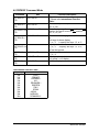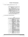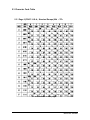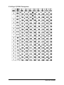
1
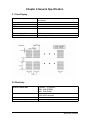
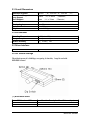
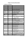
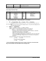
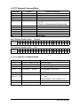
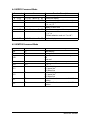
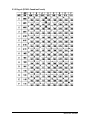
DSP-800F
VFD Customer Display
User Manual
1
Manual Version: 2.0
Release Date: 8/30/2007
Table of Contents
CHAPTER 1 INTRODUCTION ......................................................................3
1.1 Features .................................................... .................................................3
1.2 Outline..................... ................................................................................... 4
CHAPTER 2 GENERAL SPECIFICATION....................................................5
2.1 Tube Display..................................... .................................. .......................5
2.2 Electricity ............................... ................................................... ................5
2.3 Overall Dimensions............... ................................................... .................6
2.4 Environment .............................................................................................. 6
2.5 Driver Interface.......................................................................................... 6
2.6 DIP Switch Settings................... .............................................. ..................6
CHAPTER 3 INTERFACE ...................................................... .......................8
3.1 Interface ............................................................................. ........................8
CHAPTER 4 COMMAND DESCRIPTION .....................................................9
4.1 EPSON Command Mode.......................................... .............................. . 9
4.2 UTC Standard Command Mode............................................................. .11
4.3 UTC Enhance Command Mode............................................................. .11
4.4 AEDEX Command Mode ........................................ ............................... .12
4.5 ADM788 Command Mode ...................................................................... .12
4.6 DSP800F Command Mode..................................................................... 13
4.7 CD5220 Command Mode ....................................... .................................14
CHAPTER 5 CHARACTER SET .................................................................16
5.1 U.S.A. / Standard Cha racter Set ( 20h - 7Eh) ........................................16
5.2 International Character Selection.......................................................... 16
5.3 Character Code Table ............................................................................ .17
5.3.1 Page 0 (PC437: U.S.A., Standard Europe)........................... ...........17
5.3.2 Page 1 (Japanese Katakana) ............................... ...........................19
5.3.3 Page 2 (PC850: Multilingual) ............................ ..............................2 0
5.3.4 Page 3 (PC860: Portuguese).................................................... .......21
5.3.5 Page 4 (PC863: Canadian-French) .................................................2 2
5.3.6 Page 5 (PC865: Nordic)................................................... ................23
CHAPTER 6 INSTALLATION GUIDE .........................................................24
2
Manual Version: 2.0
Release Date: 8/30/2007
Chapter 1 Introduction
1.1 Features
The DSP-800F is Vacuum Fluorescent Displays which display 20
columns and 2 lines.
Blue – green fluorescent color is easy on the eyes.
The display panel is movable so that it can be adjusted for the best
viewing angle.
The customer display has different height by adjusting the support.
The interface of customer display is RS-232,with baud rates from 4800 up
to 9600bps, or USB for DSP-800F.
The user defined and international character sets are standard of
customer display.
Attention
1.
This specification shall apply only to the product(s) coming along whit
this manual inside.
2. This manual many not apply to the previous or later product(s).
3.
This specification many be modified without any notice. If it is
necessary for “customers” to have a latest manual about specification,
please inquire your suppliers.
3
Manual Version: 2.0
Release Date: 8/30/2007
1.2 Outline
The customer display outline has included of three parts: the panel, the
support, and the base.
The standard VFD customer display should include following accessories.
Item
1
2
3
4
5
6
7
8
9
Description
Dimension(mm) Q’ty
Panel of DSP- 800F
225(W) x 50(D) x 92(H) 1
Support (Short)
88(H), 33(Diameter) 1
Support (Long)
220(H), 33(Diameter) 1
Base
190(W) x 95(D) x 50(H) 1
Metal Parts
1
Driver & Manual Disk
1
D - SUB 9PIN RS-232 Cable
1
Screw P3.1x15 for Interface Conversion Adapter
4
+ 5V PC 4P Plug Power Kit or
USB Power Kit or
1
100V~240V Universal Adapter (5V / 2A) or
110V US or 230V Europe 2P Adapter (5V / 1A)
※Above accessories may be different due to c ustomers’ requirement when delivery
4
Manual Version: 2.0
Release Date: 8/30/2007
Chapter 2 General Specification
2.1 Tube Display
Display pattern
Brightness
Character Type
Character Size
Vacuum Fluorescent Display
Blue Green
5 x 7 Dot Matrix
350 ~ 700 cd / m²
95 Alphanumeric & 32 International Characters
5.5mm(W)x 10.5 mm(H)
Character Number
Character Pitch
20x2
Refer the figure 2.1
Customer Display
2.2 Electricity
Central Control Unit
Connector
Power Source
Power Consumption
Processor:HT48RU80
ROM:64K EPROM
RAM:32K SRAM
10 PIN Phone Jack Connector
5 PIN USB Connector
DC + 5V
3 Watts Average
5
Manual Version: 2.0
Release Date: 8/30/2007
2.3 Overall Dimensions
Dimension of Panel
Dimension of Support
Long Support
Short Support
Dimension of Base
Viewing Angle
Horizontal Rotation
Weight
225 mm (W)x 50 mm(D)x 92 mm (H)
220mm (H)x 33mm (Diameter)
88mm (H)x 33mm (Diameter)
190 mm (W)x 95 mm(D)x 55 mm (H)
Max. 45°
Max. 340°
About 0.8 Kg
2.4 Environment
Operating Temperature
Storage Temperature
Relative Humidity
+ 10℃ to + 40℃
-10℃ to + 50℃
0% to 90% RH
2.5 Driver Interface
Driver Interface
RS232 or USB
2.6 DIP Switch Settings
The default protocol is 9600 bps, non-parity, 8 data bits, 1 stop bit and with
DTR/DSR control.
( I ) Baud Rate Select
SW Number – SW1
OFF
ON
Function Description Baud Rate (bps)
9600
4800
6
Manual Version: 2.0
Release Date: 8/30/2007
( II ) Command Type Select
SW4
OFF
OFF
OFF
ON
ON
ON
ON
SW Number
SW3
SW2
OFF
ON
ON
OFF
OFF
ON
ON
ON
OFF
ON
OFF
ON
OFF
ON
Function description
Command Type
Software Defined
Hex Code
EPSON POS D101
UTC Standard
UTC enhance
AEDEX
ADM788
DSP-800F
CD5220
01
02
03
04
05
06
07
( III ) International Character Set
SW Number
Function Description
SW 8 SW 7 SW 6 SW5
OFF
OFF
OFF
OFF
OFF
OFF
OFF
OFF
OFF
OFF
OFF
ON
ON
ON
ON
ON
ON
ON
ON
OFF
OFF
OFF
ON
ON
ON
ON
OFF
OFF
OFF
OFF
ON
ON
ON
ON
OFF
ON
ON
OFF
OFF
ON
ON
OFF
OFF
ON
ON
OFF
OFF
ON
ON
ON
OFF
ON
OFF
ON
OFF
ON
OFF
ON
OFF
ON
OFF
ON
OFF
ON
International Character
Set ( Code 20H-7FH)
(
Code Table
Code 80H-FFH )
PC-437 (USA)
(Standard European)
PC-850(Multilingual)
FRANCE
PC-850(Multilingual)
GERMARY
PC-850(Multilingual)
U.K.
PC-850(Multilingual)
DENMARK I
PC-850(Multilingual)
SWEDEN
PC-850(Multilingual)
ITALY
PC-850(Multilingual)
SPAIN
JAPAN
Katakana
PC-850(Multilingual)
NORWAY
PC-850(Multilingual)
DENMARK II
SLAVONIC
RUSSIAN
Factory Define
Factory Define
Factory Define
U.S.A
7
Manual Version: 2.0
Release Date: 8/30/2007
Chapter 3 Interface
3.1
RS-232
Specifications
Data Transmission Method:Asynchronous Serial
Handshaking
:DTR / DSR Control
Default Protocol
:9600 bps,non-parity,8 data bits,1 stop bit
Communication Protocol
1. Receive Data.
The DTR signal is as follow:
【HIGH】 This indicates that the display isn’t ready to receive data.
It depend on the following conditions:
The period from when the power is turned on to when the printer first becomes
ready.
When the remaining space in the receiving buffer becomes 128 bytes or less.
When the DTR signal of the printer is HIGH when the printer is selected using the
command.
【Low】This indicates that the display isn’t ready to receive data.
It depends on the following condi tions:
When the printer first becomes ready to receive data after power – on.
When the remaining space in the receiving buffer becomes 128 bytes or more.
When the DTR signal of the printer is LOW when the printer is selected using the
command.
2. Transmit Data.
After confirming the DSR is LO W, data transmitted to printer.
3.2 USB
Fully Compliant with USB Specification v2.0 (Full-Speed)
On Chip USB 1.1 transceiver
On-chip 96MHz clock generator
Supports RS-422/RS-485 like serial interface (TXD, DTR_N, and RTS_N pins
should be externally pulled-up to 5V)
Supports RS232-like Serial Interface
8
Manual Version: 2.0
Release Date: 8/30/2007
Chapter 4 Command Description
4.1 EPSON Command Mode
Command
HT
BS
US LF
LF
US CR
Hex
09
08
1F0A
0A
1F0D
Function Description
Move cursor right
Move cursor left
Move cursor up
Move cursor down
Move cursor to right-most position
CR
HOM
USB
0D
0B
1F42
Move cursor to left-most position
Move cursor to home position
Move cursor to bottom position
US $ xy
1F24 x y
US C n
1F 43 n
CLR
CAN
US X n
0C
18
1F 58 n
US E n
1F 45 n
ESC @
ESC t n
1B 40
1B 74
ESC R n
1B 52 n
US r n
1F 72 n
US MD1
US MD2
US MD3
1F 01
1F 02
1F 03
US﹒n
1F 2En
US﹐n
1F 2Cn
US;n
1F 3Bn
US ﹟n m
1F23 n m
1F 3A
Specify period display
n=display character code
Specify comma display
n=display character code
Specify semicolon (period + comma) display
n=display character code
Specify display annunciator ,, turn the annunciator
at“m”column on or off
n=0 , 1 (off , on) ;0≦m≦20
Select / cancel download character set
n =0,cancel;n=1,selected
Specify /cancel the window range
n=1,2,3,4(four windows);s=0,1(disable , enable)
1≦x1≦x2≦20(column);1≦y1≦y2≦2(row)
Set starting/ending position of macro definition
1F 40
Execute self -test
ESC % n
1B 25 n
ESC % n
1B 57 n s
(x1y1x2y²)
US:
US@
Move cursor to specified position
1≦x(column)≦20 ; 1≦y(row)≦2
Select/cancel cursor display
n=0,canceled ; n=1 selected
Clear display screen
Clear cursor line
Brightness adjustment
1≦n≦4
Blink display screen
0≦n≦255 (n*50msec)ON / (n*50msec)OFF
n = 0,blinking is canceled
n = 255,display is turned o ff
Initialize display
Select character code table
0≦n≦5(Please refer “chapter 5”)
Select international character set
(Please refer International Font Set Table)
Select/cancel reverse character
n = 0, canceled ; n=1, select
Specify overwrite mode
Specify vertical scroll mode
Specify horizontal scroll mode
9
Manual Version: 2.0
Release Date: 8/30/2007
US T h m
1F 54 h m
US U
1F 55
Display time
0≦h≦23 ; 0≦m≦59
Display of time counter
*International Font Set Table
n (Hex)
00h
01h
02h
03h
04h
05h
※
International Font Set
U.S.A.
FRANCE
GERMANY
U.K.
DENMARK I
SWEDEN
n (Hex)
06h
07h
08h
09h
0AH
International Font Set
ITALY
SPAIN JPAIN
NORWAY
DENMARK II
Specify decimal point , comma semicolon , annunciator *
(1) US﹒n(Decimal Point)US , n(Comma)/ US ; n(Semicolon)
The displayed character codes are form 32(20h) to 127(7Eh)
,and 128(80h)
to 255(FFh)
in the chrarater code
table . The period /comma / semicolon displayed only for n. The period is not displayed for the
subsequent display characters.
(2) US# n m (annunicator)
:
[range]n = 0(00h) or 1(01h) / m = 0(00h) ~20(14h)
[notes]When n = 0, the annunicator at column m is turned o ff.
When n = 1, the annunicator at column m is turned o ff.
“m”specify column number (the most left column is column 1) at which
annunciator to be turned on / off is placed.
When m=0, all annunciators are turned on or off.
Once an annuciator (s) is turned on, it remains on until turned off by this
command ,the ESC@ or US@ command is executed, or the power is
turned off .
[example]
:To turn on the annunciator at the third column :
[n = 01h], [m = 03h]
To turn off all the annunciators:
[n = 00h], [m = 00h]
※Above commands relating decimal poin t, comma, semicolon, and annunciator
may not be available due to hardware limit of display tube.
10
Manual Version: 2.0
Release Date: 8/30/2007
4.2 UTC Standard Command Mode
Command
BS
HT
LF
CR
DC0p
08
09
0A
0D
10p
n (Hex)
DC1
DC2
DC3
DC4
ESC d
US
11
12
13
14
1B 64
1F
Function Description
Back space
Horizontal tab
Line feed
Carriage return
Move cursor specified position,
0≦p≦39
(Please refer Row character Position chart)
Over write display mode
Vertical scroll mode
Cursor on
Cursor off
Change to UTC enhanced mod e
Clear display
Row Character Position Chart (Decimal)
0 1 2 3 4 5 6 7 8 9 10 11 12 13 14 15 16 17 18 19
Row1
Row2 20 21 22 23 24 25 26 27 28 29 30 31 32 33 34 35 36 37 38 39
Row Character Position Chart (Hex)
Row1 00 01 02 03 04 05 06 07 08 09 0A 0B 0C 0D 0E 0F 10 11 12 13
Row2 14 15 16 17 18 19 1A 1B 1C 1D 1E 1F 20 21 22 23 24 25 26 27
4.3 UTC Enhance Command Mode
Command
n (Hex)
ESC u A﹒﹒CR 1B 75 41[data x 20]0D
ESC u B﹒﹒CR 1B 75 42[data x 20]0D
ESC u D﹒﹒CR 1B 75 44[data x 45]0D
ESC u E﹒﹒CR 1B 75 45 hh“:”mm 0D
Function Description
Upper line display
Bottom line display
Upper line message scroll continuously
Set and display 24 hour time
0 ≦ h,m ≦
ESC u F﹒﹒CR 1B 75 46[data x 45]0D 9
Upper line message scroll once pass
1B 75 48 n m 0D
Change attention code
ESC u H﹒﹒CR
32 ≦ n,m
(Default attention code n=1Bh,m=75h )
ESC u 1﹒﹒CR 1B 75 49[data x 40]0D Two line display
ESC RS﹒﹒CR 1B 0F 0D
Change to UTC standard mode
11
Manual Version: 2.0
Release Date: 8/30/2007
4.4 AEDEX Command Mode
!
!
!
!
Command
# 1..CR
# 2..CR
# 4..CR
# 5..CR
Hex
21 23 31[data x 20]0D
21 23 32[data x 20]0D
21 23 34[data x 45]0D
21 23 35 hh“:”mm 0D
! #
! #
! #
5 CR
6..CR
8..CR
21 23 35 0D
21 23 36[data x 45]0D
21 23 38 n m 0D
! #
9..CR
21 23 39[data x 40]0D
Function Description
Upper line display
Bottom line display
Upper line message scroll continuously
Set and display 24 hour time
0≦h , m≦9
Display 24 hour time
Upper line message scroll once pass
Change attention code
32≦n , m
(Default attention code n=“1”,m=“#”)
Two line display
4.5 ADM788 Command Mode
Command
CLR
CR
Hex
0C
0D
0E
SLE1
SLE2
DC0
0F
10 n
11 n
DC1
12 n
DC2
SF1
SF2
1E
1F
Function Description
Clear display
Carriage return
Clear up line and move cursor to upper line
lsft
most end
Set period to upper line last n postion
1≦n≦7
Set line blinking
n=1,upper line
n=2,lower line
Set line blinking
n=1,upper line
n=2,lower line
Clear field 1 and move cursor to field 1 fast
position
Clear field 2 and move cursor to field 2 fast
position
12
Manual Version: 2.0
Release Date: 8/30/2007
4.6 DSP800F Command Mode
Command
Hex
EOT SOH I n
ETB
04 01 49 n17
EOT SOH P n
ETB
04 01 50 n17
EOT SOH C n m
ETB
04 01 43 n m 17
04 01 53 n 17
EOT SOH S n
ETB
EOT SOH D n m
ETB
EOT SOH A n
ETB
EOT SOH = n
ETB
EOT SOH%
ETB
04 01 44 n m 17
04 01 41 n 17
04 01 3D n 17
04 01 25 17
Function Description
Select international character set
(Please refer International Font Set
Table)
Move cursor specified position
49≦n≦88
Clear display range from n position to m
position and move cursor to n position
49≦n≦m≦88
to
Save the current display data (40 character)
character
to
n’th layer for demo display
1≦n≦3 (n specify the layer 1,2, or 3)
Display the saved data
1≦n≦3 (n specify the layer 1,2, or 3)
“m”can be ignored
Brightness adjustment
1≦n≦4
Select peripheral device
n=1,printer ; n=2, display
Initialize display
*International Font Set Table
n (Hex)
International Font Set
30h
U.S.A.
31h
FRANCE
32h
GERMANY
33h
U.K.
34h
DENMARK I
35h
SWEDEN
36h
ITALY
37h
SPAIN
38h
JAPAN
39h
NORWAY
3Ah
DENMARK II
13
Manual Version: 2.0
Release Date: 8/30/2007
4.7 CD5220 Command Mode
Command
ESC DC1
ESC DC2
ESC DC3
ESC Q A CR
ESC Q B CR
ESC Q D CR
ESC [D
BS
ESC [C
HT
ESC [A
ESC [B
LF
ESD [H
HOM
ESC [L
CR
ESC [R
ESC [K
ESC 1 x y
ESC@
ESC W s x 1
X2 y
CLR
CAN
ESC*n
Hex
1B11
1B12
1B13
1B51 41 [N]20 0D
1B51 42 [N]20 0D
1B51 44 [N]m20
0D
1B 5B 44
08
1B 5B 43
09
1B 5B 41
1B 5B 42
0A
1B 5B 48
0B
1B 5B 4C
0D
1B 5B 52
1B 5B 4B
1B 6C x y
1B 40
1B 57 s x 1 x2 y
0c
18
1B2A n
ESC & s n m 1B 26 s n m
[a(p1..p5)
] m- [a(p1..p5)](m-n+1)
(
n+1)
1B 3F n
ESC ? n
ESC % n
ESC _ n
1B 25 n
1B 5F n
Function Description
Overwrite mode
Vertical scroll mode
Horizontal scroll mode
Set string mode ,write string to upper line
Set string mode ,write string to lower line
Upper line message scroll continuously
m<40
Move cursor left
Move cursor left
Move cursor right
Move cursor right
Move cursor up
Move cursor down
Move cursor down
Move cursor to home position
Move cursor to home position
Move cursor to left-most position
Move cursor to left-most position
Move cursor to right -most position
Move cursor to bottom position
Move cursor to specified position
1≦x≦20(column); y=1,2(row)
Initialize display
Enable or disable the window range at
horizontal
Scroll mode
s=0,1(disable , enable)
1≦x1≦x2≦20(column); y=1,2(row)
Clear display screen , and clear string
mode
Clear cusor line , and clear string mode
Brightness adjustment
1≦n≦4
Define download characters
s=1 ; 32≦n≦m≦126 ;a=5
(p1..p5 = pattern1..parttern5)
Delete download characters
32≦n≦126(n=character code)
Select / cancel download character set.
n=0,canceled ; n=1,selected
Set cursor ON/OFF
n=0,1(Off,On)
14
Manual Version: 2.0
Release Date: 8/30/2007
ESC f n
ESC c n
1B 66 n
1B 63 n
1B 3D n
ESC = n
Select international fonts set
Select fonts, ASCII code or JIS code
Select peripheral device
n=1,printer ; n=2,display ; n=3, printer &
display
(REMARK)
*While using command “ESC Q A”or “ESC Q B”, these two commands could be
used combining with terminal printer – TP 2688 or TP36887
*If using command “ESC Q A”or “ESC Q B”,others commands can’t be used except
using command “CLR”or “CA N”to change operating mode.
*If using command “ESC Q D”,message on upper line will move continuously till receiving
a new command , clearing upper line , and moving cursor to most le ft position on upper
line.
* International Font Set Table
n
(Decimal)
International Font Set
A
G
I
J
U
F
S
N
W
D
E
L
R
U.S.A.
GERMANY
ITALY
JAPAN
U.K.
FRANCE
SPAIN
NORWAY
SWEDEN
DENMARK I
DENMARK II
SLAVONIC
RUSSIA
Reserved
* Select Code Table
n
International Font Set
(Decimal)
A
compliance with ASCII code
J
compliance with JIS code
L
compliance with RUSSIA code
R
compliance with SLAVONIC code
15
Manual Version: 2.0
Release Date: 8/30/2007
Chapter 5 Character Set
5.1 U.S.A. / Standard Character Set ( 20h - 7Eh)
5.2 International Character Selection
16
Manual Version: 2.0
Release Date: 8/30/2007
5.3 Character Code Table
5.3.1 Page 0 (PC437: U.S.A., Standard Europe) 00h – 7Fh
To be continued on next page…
17
Manual Version: 2.0
Release Date: 8/30/2007
80h – FFh
18
Manual Version: 2.0
Release Date: 8/30/2007
5.3.2 Page 1 (Japanese Ka takana)
19
Manual Version: 2.0
Release Date: 8/30/2007
5.3.3 Page 2 (PC850: Multilingual)
20
Manual Version: 2.0
Release Date: 8/30/2007
5.3.4 Page 3 (PC860: Por tuguese)
21
Manual Version: 2.0
Release Date: 8/30/2007
5.3.5 Page 4 (PC863: Canad ian-French)
22
Manual Version: 2.0
Release Date: 8/30/2007
5.3.6 Page 5 (PC865: No rdic)
23
Manual Version: 2.0
Release Date: 8/30/2007
Chapter 6 Installation Guide
24
Manual Version: 2.0
Release Date: 8/30/2007