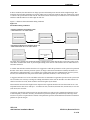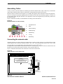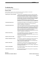
1
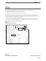
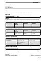
eNet Interface Installation Manual
ves_header.jpg
VES, LLC
eNet Interface Installation Manual
VF3511-00, Revision E01.03
Issue Date: 11/18/2008
Revision History
Revision
Date
Status
Description
E01.00
07/26/2008
Initial release
Modify original from parent company.
E01.02
09/08/2008
internal edits
Added part number for manual, changed from central time to eastern standard time,
changed references from eLAN Lite to Elite, modified image of figure 3-3, added
references for English units. Change name of network card from “VES Network
Card” to “eNet Interface”. Change contact information from “Central Time” to “Eastern Standard Time”. Global change of eLITE to Elite Panel. Global change from DIL
to DIP. Add reference for configuring with Loop Explorer and eSP Discovery. Change
from Syncro to eLAN and Elite. Update VES part numbering.
E01.02
09/16/2008
Internal edits
Increased font-size of title and centered image on front-cover. Added RMA and
warranty return process in Introduction, Section 1. Add “location security” to step one
of “To complete the installation:”, Installation, Section 3. Identify correct values for
Specifications, Appendix A. Added step#2 to Installation, Section 3, “Remove AC
and battery power to the eLAN or Elite Panel”.
E01.03
11/18/2008
Content
changes under
UL project
08CA27859.
Reference to optical fiber removed from Section 2, Overview. Added further details to
Section 3, Installation describing the unintended increase in cable length that occurs
during a failure of the eNET Interface Card. Added low temperature, high
temperature and relative humidity to the Operating Environment of Appendix A,
Specifications. Changed document revision on all footers from E01.02 to E01.03.
VES, LLC
eNet Interface Installation Manual
VF3511-00, Revision E01.03
Underwriters Laboratories (UL)
File number (S 8485)
Fire Alarm Equipment
VES, LCC
NFPA
FM Global Technologies LLC (FM APPROVALS)
VES, LCC
FCC Compliance
This equipment has been tested and found to comply with the limits for a Class A digital device, pursuant to Part 15 of the FCC Rules. These limits are
designed to provide reasonable protection against harmful interference when the equipment is operated in a commercial environment. This equipment
generates, uses, and can radiate radio frequency energy and, if not installed and used in accordance with the Installation Manual, may cause harmful
interference to radio communications. Operation of this equipment in a residential area is likely to cause harmful interference in which case the user will
be required to correct the interference at his own expense. Any changes or modifications not expressly approved by VES, LCC could void the user’s
authority to operate this equipment under the rules and regulations of the FCC.
Operation is subject to the following two conditions:
(1) This device may not cause harmful interference, and
(2) This device must accept any interference received, including interference that may cause undesired operation.
VES, LLC
eNet Interface Installation Manual
VF3511-00, Revision E01.03
Copyright © 2008 by VES, LLC
All rights reserved.
VES is a registered trademark of VES, LLC. VES, LLC is a wholly owned subsidiary of Kentec Electronics Ltd.
All other product or service names are the property of their respective owners.
VES, LLC
eNet Interface Installation Manual
VF3511-00, Revision E01.03
i
Contents
Section 1
Introduction
Using This Manual . . . . . . . . . . . . . . . . . . . . . . . . . . . . . . . . . . . . . . . . . . . . . . . . . . . . . . . . . . . . 2
Related Documentation . . . . . . . . . . . . . . . . . . . . . . . . . . . . . . . . . . . . . . . . . . . . . . . . . . . . . . . . 2
Writing styles . . . . . . . . . . . . . . . . . . . . . . . . . . . . . . . . . . . . . . . . . . . . . . . . . . . . . . . . . . . . . . . . 2
If You Need Help . . . . . . . . . . . . . . . . . . . . . . . . . . . . . . . . . . . . . . . . . . . . . . . . . . . . . . . . . . . . . 3
Contacting VES Tech Support . . . . . . . . . . . . . . . . . . . . . . . . . . . . . . . . . . . . . . . . . . . . . . . . . . . 3
RMA Returns Required . . . . . . . . . . . . . . . . . . . . . . . . . . . . . . . . . . . . . . . . . . . . . . . . . . . . . . 3
Warranty Returns. . . . . . . . . . . . . . . . . . . . . . . . . . . . . . . . . . . . . . . . . . . . . . . . . . . . . . . . . . . 3
Advanced Replacements . . . . . . . . . . . . . . . . . . . . . . . . . . . . . . . . . . . . . . . . . . . . . . . . . . . . . 4
Suspect-Product Testing . . . . . . . . . . . . . . . . . . . . . . . . . . . . . . . . . . . . . . . . . . . . . . . . . . . . . 4
Product Return Address . . . . . . . . . . . . . . . . . . . . . . . . . . . . . . . . . . . . . . . . . . . . . . . . . . . . . . . 4
Section 2
Overview
Networking 7
Section 3
Installation
Before You Begin . . . . . . . . . . . . . . . . . . . . . . . . . . . . . . . . . . . . . . . . . . . . . . . . . . . . . . . . . . . . . 8
Setting the Address . . . . . . . . . . . . . . . . . . . . . . . . . . . . . . . . . . . . . . . . . . . . . . . . . . . . . . . . . . . 9
Connecting the eNet Interface . . . . . . . . . . . . . . . . . . . . . . . . . . . . . . . . . . . . . . . . . . . . . . . . . 10
Determining the Cable Length . . . . . . . . . . . . . . . . . . . . . . . . . . . . . . . . . . . . . . . . . . . . . . . . . . 10
Assembling Cables . . . . . . . . . . . . . . . . . . . . . . . . . . . . . . . . . . . . . . . . . . . . . . . . . . . . . . . . . . . 11
Connecting the network cable . . . . . . . . . . . . . . . . . . . . . . . . . . . . . . . . . . . . . . . . . . . . . . . . . 12
Troubleshooting . . . . . . . . . . . . . . . . . . . . . . . . . . . . . . . . . . . . . . . . . . . . . . . . . . . . . . . . . . . . . 13
Network faults . . . . . . . . . . . . . . . . . . . . . . . . . . . . . . . . . . . . . . . . . . . . . . . . . . . . . . . . . . . . . 13
Zones On The eNet . . . . . . . . . . . . . . . . . . . . . . . . . . . . . . . . . . . . . . . . . . . . . . . . . . . . . . . . 14
VES, LLC
eNet Interface Installation Manual
VF3511-00, Revision E01.03
ii
Contents
Appendix A
Specifications
Electrical . . . . . . . . . . . . . . . . . . . . . . . . . . . . . . . . . . . . . . . . . . . . . . . . . . . . . . . . . . . . . . . . . . . 16
Cabling . . . . . . . . . . . . . . . . . . . . . . . . . . . . . . . . . . . . . . . . . . . . . . . . . . . . . . . . . . . . . . . . . 16
Operating Environment. . . . . . . . . . . . . . . . . . . . . . . . . . . . . . . . . . . . . . . . . . . . . . . . . . . . . . . 16
Physical Specifications. . . . . . . . . . . . . . . . . . . . . . . . . . . . . . . . . . . . . . . . . . . . . . . . . . . . . . . 16
VES, LLC
eNet Interface Installation Manual
VF3511-00, Revision E01.03
Introduction
1
Section 1
Introduction
This manual describes the installation of the eNet Interface VF1170-00.
This section describes:
• Using This Manual
• Related Documentation
• Document Conventions
• If You Need Help
• Contacting VES For Repair
The figure below illustrates the eNet Interface VF1170-00:
Figure 1-1
eNet Interface
VES, LLC
eNet Interface Installation Manual
VF3511-00, Revision E01.03
1 of 18
Introduction
VES, LLC
eNet Interface Installation Manual
1
VF3511-00, Revision E01.03
2 of 18
Introduction
1
Using This Manual
The following sections provide instructions for installing, testing and troubleshooting the eNet Interface:
Section 1
Introduction provides document conventions, the technical helpline, repair and return
information.
Section 2
Overview provides a summary features of the eNet Interface.
Section 3
Installation describes how to install, configure and troubleshoot the eNet Interface.
Appendix A
Specifications provides operating characteristics of the eNet Interface.
Related Documentation
The following documents shall be used to provide additional information for installing the eNet Interface:
• eLAN H Panel Installation Manual with Releasing VF1615-00, Rev. E03.XX
• eLAN A Panel Installation Manual with Releasing VF1635-00, Rev. E01.XX
• Elite H Installation Manual, VF3515-00, Rev.E01.XX
• Elite A Installation Manual, VF3514-00, Rev.E01.XX
Writing styles
Before you begin using this installation manual, familiarize yourself with the following stylistic conventions:
Bold type
Indicates text that you must type exactly as it appears or indicates a default value.
Italic type
Denotes a displayed variable, a variable that you must type, or is used for emphasis.
Courier font
Indicates text displayed on a computer screen.
VES, LLC
eNet Interface Installation Manual
VF3511-00, Revision E01.03
3 of 18
Introduction
1
If You Need Help
If you need technical support contact VES at (800) 274 - 9514 or email [email protected].
VES technical support is available Monday through Friday, 8:00 AM to 6:00 PM, Eastern Standard Time.
Contacting VES Tech Support
On-site technicians familiar with the product issue should contact VES Tech Support and include the:
• Product part number
• Purchase order or VES order number
• Product serial number
• Current function of the product
• Expected function of the product
• Installation of the product
RMA Returns Required
A Return Material Authorization (RMA) must be assigned to all products returning to VES. VES Tech Support will
assign an RMA to a returning product after recording information collected from the on-site technician. VES cannot
not accept product-returns that do not include an accompanying RMA number.
An RMA number is assigned when:
• A product issue is acknowledged by a VES Tech Support representative
• A product was damaged during shipping
• An order was placed using an incorrect part number *
• An order was placed using an incorrect part quantity *
• An order is no longer required *
* Restocking fees may apply.
Warranty Returns
VES Tech Support can replace a defective product when the original purchase is within the warranty period defined
in the sales contract. Check your sales-contract for more information or contact your VES sales representative about
the warranty period described in your sales-contract.
Warranty products that have been placed in service will be repaired or replaced by VES.
Warranty products that have not been placed in service will be returned to VES stock and an equivalent credit will be
provided to the contractor.
VES, LLC
eNet Interface Installation Manual
VF3511-00, Revision E01.03
4 of 18
Introduction
1
Advanced Replacements
Suspect-products that fail to operate in the field can be replaced quickly using the advanced replacement process.
The advanced replacement process is available to all contractors who maintain an acceptable line of credit with VES.
Initiate the advanced replacement process by requesting an RMA number from a VES Tech Support representative.
Advanced replacements can be shipped to your location when the suspect-product is covered under warranty and
when a replacement product is in stock. All advanced replacement products are shipped UPS ground.
Expedited Replacements
Advanced replacements can be expedited at the request of the contractor. Shipping costs associated with this
process are the responsibility of the contractor.
Returning Products
Suspect products returning to VES using the advanced replacement process must be received 30 days from the RMA
issue-date. Contractors can be billed for returning products received following this 30 day period.
Suspect-Product Testing
Suspect-products returned to VES are tested to confirm operating failures experienced in the field.
If the suspect-product is found to be functional, contractors must absorb the following expenses:
• Shipping of the advanced replacement product
• Return-shipping of the suspect-product
• Cost of the advanced replacement product
Product Return Address
Prominently display the RMA number on all packages sent to VES for return.
Ship all return products to:
Attention: RMA # _____________
VES, LLC
620 Allendale Road, Suite 175
King of Prussia, PA. 19406
VES, LLC
eNet Interface Installation Manual
VF3511-00, Revision E01.03
5 of 18
Introduction
1
This page intentionally left blank.
VES, LLC
eNet Interface Installation Manual
VF3511-00, Revision E01.03
6 of 18
Introduction
VES, LLC
eNet Interface Installation Manual
1
VF3511-00, Revision E01.03
7 of 18
Overview
2
Section 2
Overview
The eNet Interface supports Apollo loop protocol in models of the eLAN A and Elite A Panel.
It supports Hochiki loop protocol in models of the Elite H Panel.
The eNet Interface is not supported on models of the eLAN Lite Panel.
The eNet enables information to be transmitted between control panels using a secure network connection.
Connect a two-core cable to the eNet Interface to provide the network communication path. Install the network
communication path in a loop between control equipment.
Up to sixty-four eLAN or Elite Panels can be connected together using the eNet Interface. This network
can be configured for information displays such as messaging as well as controls for operating panel devices.
Figure 2-1 illustrates components on the eNet Interface:
Figure 2-1
Components on the eNet Interface
R15
S1
VES, LLC
eNet Interface Installation Manual
VF3511-00, Revision E01.03
6 of 18
Overview
2
Networking
The eNet Interface enhances the versatility of the VES fire alarm system by providing additional network
capabilities to the eLAN and Elite family of control panels.
Figure 2-2 illustrates an example of an eNet using the eNet Interface:
Figure 2-2
eNet
A
CONTROL
PANEL 1
B
CONTROL
PANEL 2
CONTROL
PANEL 3
CONTROL
PANEL 4
The VES network in Figure 2-2 above supports the following functions on the eLAN or Elite Panel:
1
Cabling wired as a ring supplies eNet communication to all Panels.
2
Short circuit detection is provided at each network connection and automatic isolation is provided at the
shorted section of cable.
3
The eNet supports 1200 meters (4000 feet) of maximum cable length between two adjacent segments.
4
A short circuit at point A automatically disconnects the shorted section and a fault condition is announced
on all panels while the entire eNet continues communicating.
5
A short circuit at points A and B automatically disconnects both sections and a fault condition is
announced on all panels while communication continues between Panels 1 and 4 and between
Panels 2 and 3.
6
All Panels compute whether faults prevent an operation determined by a cause and effect configuration
and either assume inputs to be true (if configured to default to "true upon network fault") or display, print
and log the cause and effect conditions.
7
Open circuit faults allow the network to continue operating in the same way as short circuit faults.
8
Network cabling to be standard Belden RS485.
9
Up to 64 node.
VES, LLC
eNet Interface Installation Manual
VF3511-00, Revision E01.03
7 of 18
Installation
3
Section 3
Installation
This section provides instructions for connecting cables, mounting and testing the eNet Interface for installation.
To complete the installation:
1
Notify the monitoring center and local security that the eLAN or Elite Panel will be temporarily out of service
when replacing an eNet Interface.
2
Remove AC and battery power to the eLAN or Elite Panel.
3
Set the address of the eNet Interface.
4
Remove the eNet Interface from its packaging and check its contents.
5
Open the cabinet of the eLAN or Elite Panel and remove the metal cover of the Panel Annunciator Board.
6
Connect the eNet Interface to connectors J1 and J3 of the Panel Annunciator Board and secure the
mounting with two stand-off-screws.
7
Apply power to the eLAN or Elite Panel.
8
Check LED 1 and LED 2 on the eNet Interface to identify communication from the eLAN or Elite Panel.
9
Replace the metal cover of the Panel Annunciator Board and then close the cabinet of the eLAN or
Elite Panel.
Install this product in accordance with NFPA 72, the National Electrical Code and all local codes.
Installation of the eNet Interface must be performed by personnel familiar with electronic
components. Electronic components of the eNet Interface are vulnerable to damage from
electrostatic discharge. Ground straps must be worn by installers before handling this
circuit board to prevent electrostatic discharge damage.
Before You Begin
Before you begin the installation, take a few minutes to review the installation information, gather the required items,
and complete the tasks listed below to make the installation as quick and easy as possible.
Acquire the following items that are not included with the eNet Interface, but may be required for the installation:
Communication Cabling
4
Specify required lengths of 18 through 24 AWG.
Ground Strap
1
A ground strap is required for handling circuit boards. The ground
strap is not provided in the packaging of the eNet Interface.
VES, LLC
eNet Interface Installation Manual
VF3511-00, Revision E01.03
8 of 18
Installation
3
Setting the Address
Unique address settings are required for all eNet Interfaces on the VES network. These settings establish the
communication between eLAN or Elite Panels on the VES network. Maintain each of these unique settings in a log
for future reference. Set the DIP switch on each eNet Interface to a specific binary number to assign a unique address.
Figure 3-1 illustrates eNet Interface settings:
Figure 3-1
eNet Interface Settings
Always perform these address settings with power of the control panel turned-off.
VES, LLC
eNet Interface Installation Manual
VF3511-00, Revision E01.03
9 of 18
Installation
3
Connecting the eNet Interface
To enable control panels to be connected together as a network, each panel must be connected with a eNet Interface.
The eNet Interface connects to the Panel Annunicator Board of the eLAN or Elite Panel.
The Panel Annunicator Board is located on the rear of the front-panel door. The eNet Interface is held in position on
the Panel Annunicator Board by two stand-off-screws.
To connect the eNet Interface:
1
Remove AC and battery power to the eLAN or Elite Panel.
2
Remove the metal cover of the Panel Annunicator Board.
3
Connect the eNet Interface to connector J1 and J3 on the bottom right of the Panel Annunicator Board and
secure it in position with the two stand-off-screws.
Figure 3-2 illustrates one of the eNet Interface two stand-off screws:
Figure 3-2
eNet Interface stand-off screw
Observe precautions for static electricity when handling circuit boards.
Determining the Cable Length
The eNet communications protocol has been designed to be extremely tolerant of interference and data
corruption, however as with any system, there must be limits to guarantee correct operation.
The transmission limit for this network is 3900 feet (1200 meters) and because the data is re-transmitted at each
eNet Interface, in theory, there can only be 3900 feet between each card. Using the above cable limit does not take
into account the communication failures that occur on the eNet Interface during power failures or card faults.
VES, LLC
eNet Interface Installation Manual
VF3511-00, Revision E01.03
10 of 18
Installation
3
In these conditions, the eNet Interface no longer operates and instead passes network traffic straight through. This
means that the total cable length between cards on either side of a failed one would be 7800 feet (2400 meters), which
is outside of the specification for this network. This fault scenario could clearly be extended to more eNet Interfaces
and this would add 3900 feet of cable length in each case.
Figure 3-3 illustrates these unintended cabling conditions
Figure 3-3
Unintended cabling conditions
INTENDED COMMUNICATION BETWEEN THREE
CARDS USING 3900 FT OF CABLE LENGTH
eNET INTERFACE 3
eNET INTERFACE 2
3900 FT
eNET INTERFACE 3
3900 FT
UNINTENDED COMMUNICATION BETWEEN TWO OF THE
THREE CARDS USING 7800 FT OF CABLE LENGTH
eNET INTERFACE 1
eNET INTERFACE 2
FAILS
eNET INTERFACE 3
7800 FT
The figure above illustrates the unintended cabling condition caused when eNet Interface card 2 fails. Failure of the
card causes communication traffic to pass through resulting in the 7800 FT cable distance between eNET Interface 1
and eNET Interface2.
A sensible fault tolerance limit has therefore to be suggested to enable the performance of the system to be predicted.
Because of the nature of the fire protection system, its design is biased towards inherent reliability and failure of a
eNet Interface, although possible, is very unlikely. Fire control panels also have substantial back up power systems,
therefore, the likelihood of a total power failure under operational conditions, is also extremely rare.
A suggested tolerance level of one card failure is therefore recommended. To guarantee operation of the system with
one card failure it is necessary to arrange the cabling such that the failure will not introduce more than 3900 feet of
cable between the two cards, which would be connected together by the failure.
This means that the total cable length between adjacent cable segments should not be more than 3900 feet. It is not
important how the 3900 feet is made up i.e. it could be 320 feet (100 meters) and 3600 feet (1100 meters) or 1970 feet
(600 meters) and 1970 feet.
Using these general rules and the specified or equivalent cable types will provide a guaranteed performance of networks with plenty of tolerance. In reality, the networked system will operate quite satisfactorily with longer cable
runs and if a system is required which is outside of the parameters specified, the manufacturer should be consulted for
guidance on specific designs.
VES, LLC
eNet Interface Installation Manual
VF3511-00, Revision E01.03
11 of 18
Installation
3
Assembling Cables
Contrary to earlier preferred methods of terminating the shield on shielded cables, today’s EMC noisy environments
require that the shields of these cables be connected to earth-ground at all points on the system.
The most effective method of achieving this is to use EMC cable glands, which connect the shield to the gland and
earth in a 360-degree ring. Simply stripping back the insulation of the cable and connecting “pigtails” to earth is not
recommended. When using this method it is also important to ensure that the gland body is electrically connected to
the panel enclosure.
Figure 3-4 illustrates assembly recommendations for cabling of the eNet Interface:
Figure 3-4
Recommendations for cable assembly
1
Compression nut
2
Seal
3
Cable screening
4
Endless spring
5
Tapered ring
6
“O” ring
7
Gland body
Connecting the network cable
All panels will have two cables connected to another panel or panels. If either of these are not connected then a fault
will be displayed. The connection is polarity sensitive. The + and – from one panel must connect to the + and – of the
next panel and so on. The temperature of the cable should not exceed 1300 F (550 C).
It is important to ensure that the connection from the OUT+ from one panel, connects to the IN+ terminal of the next
and the OUT- from one panel connects to the IN- of the next panel and so on.
Figure 3-4 illustrates the network cable connection on the eLAN or Elite Panel:
Figure 3-4
Cable connection on the eLAN or Elite
3
4
5
6
7
8
9
10 11 12 13 14 15 16 17 18 19 20 21 22 23 24 25 26 27 28 29 30 31 32 33 34 35 36 37 38 39
+
+ - +
- +
- +
- +
- +
- +
- +
- +
NC C NO
NC C NO
NC C NO
NC C NO
NC C NO NAC 1
NO
OUT- + IN- + OUT- + IN- + OUT- + IN - +OUT- + IN NC CFIRE
1
TROUBLE FIRE 2 SUPERVISORY AUXILARY
TO DISPLAY
IN
LOOP
1OUT
IN
LOOP
2 OUT
IN
LOOP
3
OUT
-
+
NAC 2
-
NAC 3
IN
LOOP
4
+
-
NAC 4
FIRE +
ROUTING TROUBLE +
ROUTING PROGRAMMABLE +
OUTPUT 1. TBL
1. TBL
2. RES
REMOTE 3. INT
CONTROL3. INT4. CNT
AND
AUX.4. CNT
REMOTE
5. SIL
CONTROL
INPUT5. SIL
0V
6. PR1
0V
7. PR2
6. PR1
7. PR2
8. PR3
WARNING!
DO NOT PLUG OR UNPLUG RIBBON CABLES WHILE
BOARD IS POWERED.
STATIC SENSITIVE CIRCUITS. OBSERVE STATIC
HANDLING PROCEDURES AT ALL TIMES
ADDITIONAL
I/O BOARDS
COMMS
l +
2
AUX
24V
l + l
l + l +
1
l
l +
NETWORK
IN
NETWORK
OUT
1
2
3
4
5
6
7
8
9
10
11
12
13
Connect
”Network OUT”
to these terminals
14
15
16
17
18
19
20
21
22
23
VES, LLC
eNet Interface Installation Manual
-
+
+
BATTERY LOW
AC POWER FAILURE
GROUND FAULT
CHARGER TROUBLE
24VDC
-
BATTERY DISCONNECT
REMOTE PSU
Connect
”Network IN”
to these terminals
VF3511-00, Revision E01.03
12 of 18
Installation
3
Troubleshooting
This section describes network faults and zones.
Network faults
Fault messaging can appear on the eLAN and Elite Panel following installation of the network.
The table below describes these fault messages and conditions:
Network open or short circuit fault
A cabling fault is occurring between two nodes. The green and yellow
LEDs on the eNet Interface indicate that the fault is on the upper or lower
two terminals of the network connector. The upper two terminals are
incoming and the lower two terminals are outgoing. If the yellow LED is
off then the fault is on the cable connected to the upper two terminals and
if the green LED is off the fault is on the lower two terminals. A cabling
fault can be identified between two control panels when the
eNet Interface on one control panel contains an un-lit yellow LED and the
eNet Interface on the second control panel contains an un-lit green LED.
Unexpected network card
An eNet Interface is installed on a control panel that is not configured for
networking.Configure the eNet Interface on the control panel by
Autolearn, Loop Explorer or eSP Discovery.
Unexpected network node
A control panel containing an eNet Interface is connected to a functioning
network. This condition occurs when the network is not configured for the
new control panel and eNet Interface. The unexpected network panel will
respond to network events and all other panels will respond to events
from the new network panel as per the default configuration. All control
panels in the network must be configured for the number of
control panels connected. Configure each control panel of the network by
Autolearn, Loop Explorer or eSP Discovery.
Network node missing
This message displays on all network control panels when a node does
not respond to communications within 100 seconds.
This may occur if a control panel loses power or if the network in and out
connections are disconnected.
Network card not connected
A control panel is configured for networking and the eNet Interface is not
connected.
Network card address incorrect
A control panel is configured for networking with the eNet Interface and
the control panel detects an unexpected address. To change the
address, turn off primary and battery power of the control panel before
changing settings on the eNet DIP switch.
Network comms fault
Data packets are corrupted and are not being received by the control
panel. This condition indicates a very degraded transmission path
caused by excessive cable lengths, incorrect cable type or high levels of
electromagnetic interference.
Unknown network type
The control panel detects a network node type that is not supported by its
current version of software.
Unspecified network event
The control panel detects a network event type that is not supported by
its current version of software.
VES, LLC
eNet Interface Installation Manual
VF3511-00, Revision E01.03
13 of 18
Installation
3
Zones On The eNet
Zones on the eNet are network wide unlike other networks. This means that for example, device number 1 on loop 1
can be in the same zone as device number 126 on loop 4 of panel 64 and so on. This gives the system great flexibility
where zones need to be shared across panels such as risers or lift shafts but this philosophy must be understood from
the outset to enable a system design to be implemented effectively.
The system can have up to 500 zones and any device or input, on any panel, can be placed in any zone.
Identification of the alarm is by a unique address in the form:
Event type, Device type, Zone, Address, Loop, Panel name, Location text.
For this reason it is recommended that control panels on the eNet are not connected with zonal LED indicators.
Control panels on the eNet should use the front-panel LCD display to view event information relating to the zone
location. If zonal indicators are required, then LED indicators can only be provided for zones 1 to 48 on panels with
ABS fronts and zones 1 to 96 on all steel panels.
System designers must be aware however that the entire system can only have one zone 1, one zone 2 etc.
On smaller systems where the numbers of zones is likely to be much less than 500, spare zones can be used to good
effect to simplify network wide cause and effects by using zones as groups and operating upon these rather than individual devices to achieve the required functionality.
VES, LLC
eNet Interface Installation Manual
VF3511-00, Revision E01.03
14 of 18
Installation
3
This page intentionally left blank.
VES, LLC
eNet Interface Installation Manual
VF3511-00, Revision E01.03
15 of 18
Specifications
A
Appendix A
Specifications
This appendix provides electrical and environmental specifications for the eNet Interface.
Electrical
CURRENT CONSUMPTION
40 mA
Cabling
The cable type used for the network connection should be suitable for RS-485 applications and equivalent to the
following:
Up to 1970 feet (600 meters) between control panels:
BELDEN NUMBER
NOMINAL
OUTSIDE
DIAMETER
NOMINAL
CAPACITANCE
NOMINAL
IMPEDANCE
9271
0.24016” (6.1 mm)
12.2pF/foot (40 pF/m)
124 OHMS
Up to 3900 feet (1200 meters) between control panels:
BELDEN NUMBER
NOMINAL
OUTSIDE
DIAMETER
NOMINAL
CAPACITANCE
NOMINAL
IMPEDANCE
9860
0.44016” (11.18mm)
10.7pF/foot
(35pF/m)
124 OHMS
Operating Environment
Low Temperature
32 +/- 3oF (0 +/- 2oC)
Dry indoor use only
High Temperature
120+/- 3oF (49 +/- 2oC)
Dry indoor use only
Relative Humidity
93% +/- 2% @ 90 +/- 3oF
(32 +/- 2oC)
This device functions in an
atmosphere of relative humidity up
to 93 percent, non-condensing.
Physical Specifications
DIMENSIONS
VES, LLC
eNet Interface Installation Manual
4.25” x 3.5”
VF3511-00, Revision E01.03
16 of 18
Specifications
A
This page intentionally left blank.
VES, LLC
eNet Interface Installation Manual
VF3511-00, Revision E01.03
17 of 18
VES, LLC
eNet Interface Installation Manual
VF3511-00, Revision E01.03
18