1
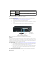
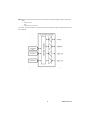
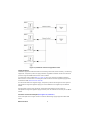
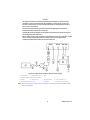
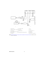
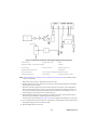
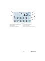
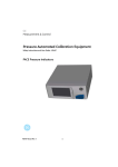
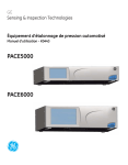
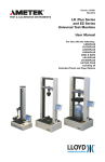
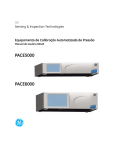
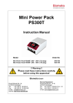
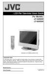
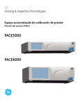
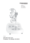
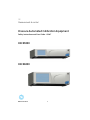
GE Measurement & control Pressure Automated Calibration Equipment Safety Instructions and User Guide - K0447 PACE5000 PACE6000 K0447 Issue No. 9 1 10 10a 9a 2 1 1 2 3 PACE6000 4 5 6 7 8 3 4 5 6 7 8 10 9 PACE5000 Figure 1 Key to Figure 1 1 Fuse and power supply switch on/off 2 Electrical rating 3 +ve supply port 4 -ve supply port 5 Pressure rating 6 Output port 7 Vent port Reference port 9 PACE 5000 9a PACE 6000 10 Control module 10a Blanking Plates 2 8 K0447 Issue No. 9 Introduction The PACE5000 single-channel and PACE6000 single/dual-channel, Pressure Automated Calibration Equipment measures and controls pneumatic pressures and displays, on a touchscreen, the pressure measurement and controller status. The touch-screen enables selections and settings in both measure and control modes. The instrument can be operated remotely through communication interfaces. Safety • Do not use this device for any other purpose than that stated. • Do not apply pressures above the Maximum Working Pressure (MWP) stated on the rear panel (Ref: Figure 1, item 5). • Do not apply electrical power above the maximum values stated on the rear panel (Ref: Figure 1, item 2). • (Ref: K0443 PACE user manual) for general pressure equipment requirements. MWP stated on rear panel. Pressure media clean, dry, nitrogen or air compatible with stainless steel, acrylic, nitrile. Pressure connections ISO228/1 G 1/8 parallel threads (DIN ISO228/1, JIS B0202) (filtered). Ref: Sales Data sheet for the complete range of adaptors Pneumatic connections In the event of a power failure or other fault condition the customers system should have other means for indicating pressure in pressure lines connected to the PACE. Fit manual vent valves to pressure lines connected to the PACE +ve source input port and output port to allow safe venting to atmosphere of these pressure lines in event of power failure or other fault condition WARNINGS ONLY USE EQUIPMENT WITH THE CORRECT PRESSURE RATING. BEFORE APPLYING PRESSURE, EXAMINE ALL FITTINGS AND EQUIPMENT FOR DAMAGE. REPLACE ALL DAMAGED FITTINGS AND EQUIPMENT. DO NOT USE ANY DAMAGED FITTINGS AND EQUIPMENT. THIS EQUIPMENT IS NOT RATED FOR OXYGEN USE. Electrical connections WARNINGS THE GROUND LEAD OF THE INSTRUMENT MUST BE CONNECTED TO THE AC SUPPLY PROTECTIVE SAFETY GROUND. ISOLATE THE POWER SUPPLY BEFORE MAKING ANY ELECTRICAL CONNECTIONS TO THE REAR PANEL. K0447 Issue No. 9 3 Packaging Check the contents of the PACE5000/6000 packaging with the list that follows: Packaging List i) ii) iii) iv) PACE5000 or PACE6000 Pressure Controller. Cable, power supply. User guide and CD (UD-0001) containing the full documentation suite. Pneumatic Control Module blanking plate (keep this plate for future use). Caution AFTER REMOVING A CONTROL MODULE, USE A BLANKING PLATE TO KEEP THE FLOW OF COOLING AIR. AFTER UNPACKING AN INSTRUMENT THAT HAS BEEN IN COLD CONDITIONS ALLOW TIME TO STABILISE AND ANY CONDENSATION TO EVAPORATE. Preparation for Use The instrument can be used as a: • Free-standing instrument positioned on a horizontal surface. • Rack-mounted in a standard 19 inch rack using the rack-mount option kit (Ref: K0443, Section 2.5, Rack-mount Option). For free-standing instruments, the feet on the front of the base can be used elevate the instrument to a better viewing angle. Note: Do not obstruct the air cooling outlet on the underside of the instrument and allow a free flow of air around the instrument, especially at high ambient temperatures. Pneumatic connection 4 K0447 Issue No. 9 Connection Input Output Port supply + supply Output Vent Reference ISO228/1 G 1/8 parallel threads (DIN ISO228/1, JIS B0202) ISO228/1 G 1/8 parallel threads (DIN ISO228/1, JIS B0202) Ref: Sales Data sheet for the complete range of adaptors. Pressure supply (Ref: Figure 2) 1. The pressure supply must be clean, dry gas, nitrogen or air and at the correct pressure, (Ref: K0443, Section 6, Reference and Specification). 2. Ensure the user systems can be isolated and vented. 3. Connect pressure and vacuum supplies to the SUPPLY + and SUPPLY - connection ports. 4. Connect the Unit Under Test (UUT) to the required outlet connection port. 2 1 1 connector 2 Bonded seal Figure 2-1, Pneumatic Connections Note: For instruments with NPT connections, use applicable pressure sealing. Installation The instrument requires a positive pressure supply, instruments operating in an absolute range or negative pressure range require a vacuum supply. A vacuum supply should be used for a fast response for instruments operating near atmospheric pressure. For dual channel operation two independent pressure and vacuum supplies can be used. Note: When using two pressure modules (Ref: K0443, Section 4.9, Pressure module replacement), make sure that: • The module with the highest pressure rating is fitted to the right hand side Module 1 position as viewed from the rear of the product, refer to (Ref: Fig 2-1) • If two modules have the same pressure rating, make sure that the module with the higher serial number is fitted to the right hand side Module 1 position as viewed from the rear of the product. Note: All pneumatic connections must comply with the Pressure Equipment Directive (PED) or other regional pressure standards. K0447 Issue No. 9 5 Note: When connecting the output ports of two pressure modules together make sure both are either: • below 70 bar OR • between 100 to 210 bar. To prevent over-pressurisation of pneumatic parts and maintain compliance with the PED do not mix categories. Figure 2-2, PACE CM pressure manifold pneumatic diagram 6 K0447 Issue No. 9 Figure 2-3, Pneumatic connections typical Use Cases Supply equipment Pneumatic supplies should have isolation and venting valves and, where necessary, conditioning equipment. The positive pressure supply should be regulated to between 110% of the full-scale pressure range and MWP stated on the control module. To protect the control module (Ref: Fig 1, item 10), from over-pressure a suitable protection device (such as a relief valve or bursting disc) must be fitted to limit the applied supply pressure to below the MWP (Ref: K0443 User Manual). On instruments without a negative supply, the positive pressure discharges from the system to atmosphere through the negative supply port. Fit the diffuser to the negative port to diffuse airflow. During system pressure vent operations, the pressure discharges from the system to atmosphere through the negative supply and vent ports. Fit a diffuser to the vent port to diffuse airflow. Pneumatic Connection Examples (Ref: Figures 3a, 3b and 3c) These examples show a single channel connection detail using supply equipment described above. K0447 Issue No. 9 7 Caution: Using the vent function can damage rate-sensitive equipment connected to this controller. set the rate of change for the equipment to a safe value. use the vent function to reduce pressure at a controlled rate (task rate setting) before the vent valve opens to atmosphere. Do not exceed the maximum pressures stated in the appropriate Component Maintenance Manual for the unit under test. Carefully de-pressurize all pipes to atmospheric pressure before disconnecting and connecting to the unit under test. Before testing, set the rates of change for the PACE instrument to a safe value. A high rate of change can damage sensitive components. Refer to the appropriate Component Maintenance Manual for the unit under test. Figure 3a, Pneumatic Connections without vacuum supply 1 Pressure source 2 Supply isolation valve 3 Filter 4 Regulate to between 110% full-scale and MWP 5 Diffuser * 6 Unit under test 9 Optional differential connection 8 7 Optional reservoir † 8 a atmosphere 10 Manual external vent valves Protection device Note: (Ref: K0443 PACE User Manual, Section 6,Reference and Specification) for details of other system components. 8 K0447 Issue No. 9 Figure 3b, Pneumatic Connections with vacuum supply 3 Filter 4 Regulate to between 110% full-scale and MWP 1 Pressure source 2 5 Diffuser * 6 Unit under test 8 Protection device 7 Supply isolation valve Optional reservoir † 9 Optional differential connection 11 Vacuum source 10 Oil mist trap 12 Normally open electrical release valve a atmosphere 8 13 Check valve ** 14 Manual external vent valves Note: (Ref: K0443 PACE User Manual, Section 6,Reference and Specification) for details of other system components. K0447 Issue No. 9 9 Figure 3c, Pneumatic Connections with negative gauge pressure generator 1) Pressure source 2) Supply isolation valve 3) Filter 4) Regulate to between 110% full-scale and MWP 5) Diffuser * 6) Unit under test 8) Protection device 7) Optional reservoir † 9) Optional differential connection ´ 8 a) atmosphere 10) Vacuum generator ‡ 11) Source pressure (regulated compressed air supply) 12) Exhaust to atmosphere 13) Check valve ‡ 14) Manual external vent valves Note: (Ref: K0443 PACE User Manual, Section 6,Reference and Specification) for details of other system components. * High pressure gas exhaust - depending on pressure range. ** Optional vacuum system kit, allows the -ve port gas to be directly discharged to atmosphere, by-passing the vacuum pump. † Optimum controller transient response and minimum time to set-point may be degraded if either the pneumatic supply or vacuum system has restricted flow. Installing a reservoir volume, which has larger capacity than the load volume, located in close proximity to the controller supply ports can improve the controller response. ‡ Optional negative gauge pressure generator kit, allows the -ve port to directly discharge to atmosphere, by-passing the negative gauge pressure generator. To protect the control module (Fig 1, item 10 or 10a), for ranges above 100bar, from over-pres8 sure a suitable protection device (such as a relief valve or bursting disc) must be fitted to limit the applied supply pressure to below the MWP. Optional differential connection kit. 10 K0447 Issue No. 9 Operation (Ref: Figure 4A, 4B and 4C) After the power-up sequence the instrument shows the default display on the touch screen. The touch screen divides into a number of mimic keys. 5 Measured Pressure 1 bar g 2 4 Control 3 Figure 4A, Single Channel Display (PACE5000) 1 Status 2 Switches between measure and control modes 3 Enter new set-point value 4 Controller set-up menu 5 Measure mode set-up menu 5 1 2 4 3 Figure 4B, Dual Channel Display (PACE6000) 1 Status 2 Switches between measure and control modes 3 Enter new set-point value 4 Controller set-up menu 5 Measure mode set-up menu Note: The PACE 6000 can be set to show a single channel display. K0447 Issue No. 9 11 Figure 4C 1 Back space (deletes last entered character) 3 Enters decimal point 5 Selects new digit for set-point value 2 Switches positive/negative value 4 Escape - exits this menu 6 Accepts (enters) new complete set-point value 12 K0447 Issue No. 9 Maintenance (Ref: K0443 User Manual, Section 4, Maintenance) for routine maintenance. Cleaning When necessary, clean externally using a damp lint-free cloth and mild liquid detergent. General Specification Display LCD: Colour display with touch-screen Operating temperature 10°C to 50°C (50° to 122°F) Storage temperature -20°C to 70°C (-4° to 158°F) Ingress protection IP20 (EN60529) Operating humidity 5% to 95% RH (non-condensing) Vibration MIL-PRF-28800 Type 2 class 5 style E/F EMC EN 61326-1 Electrical safety EN 61010-1, UL61010-1, CSA 22.2, No. 61010-1 and IEC 61010-1 PACE 5000: Input range: 100-240V (50/60Hz) 2A, Installation Catergory II, Fuse T2AH250V Power Supply PACE 6000: Input range: 100-120/200-240V (50/60Hz) 5A, Installation Catergory II, Fuse T5AH250V Pressure safety Pressure Equipment Directive - class: sound engineering practice (SEP) Pollution degree 2 Operating environment Indoor use only Symbols The equipment contains the following symbols to identify hazards. This equipment meets the requirements of all relevant European safety directives. The equipment carries the CE mark. This symbol, on the instrument, indicates that the user should refer to the user manual. Ce symbole, sur l’instrument, indique que l’utilisateur doit consulter le manuel d’utilisation. Ce symbole, dans le manuel, indique une situation dangereuse. This symbol, on the instrument, indicates do not throw-away in domestic bin, hazardous material, dispose correctly in accordance with local regulations. Approved Service Agents For the list of service centres: www.ge-mcs.com Trademarks All product names are trademarks of their respective company. © The General Electric Company all rights reserved. K0447 Issue No. 9 13 Intentionally Blank 14 K0447 Issue No. 9