1
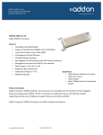
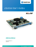
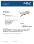
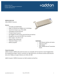
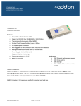
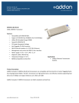
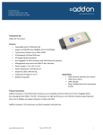
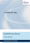
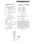
1
CONTENTS
CHAPTER 1
INTRODUCTION ................................................................................................................................. 3
1.1 Features ..................................................................................................................................................................... 3
1.2 Getting Help.............................................................................................................................................................. 4
CHAPTER 2
ARCHITECTURE................................................................................................................................. 5
2.1 Block Diagram .......................................................................................................................................................... 6
CHAPTER 3
PIN DESCRIPTION ............................................................................................................................. 8
3.1 HSMC Expansion Connector .................................................................................................................................... 8
CHAPTER 4
COMPONENTS .................................................................................................................................. 17
4.1 Featured Device: BCM8727 (U6) ........................................................................................................................... 17
4.2 General User Input/Output ...................................................................................................................................... 22
4.3 Clocks ..................................................................................................................................................................... 23
4.4 Memory Devices ..................................................................................................................................................... 24
4.5 Power ...................................................................................................................................................................... 26
CHAPTER 5
BOARD SETUP AND TEST DESIGNS ............................................................................................ 27
5.1 Board Setup............................................................................................................................................................. 27
5.2 Test Designs Using Stratix IV GX FPGA Development Kit Platform .................................................................... 28
CHAPTER 6
APPENDIX ......................................................................................................................................... 35
6.1 Revision History ..................................................................................................................................................... 35
6.2 Copyright Statement................................................................................................................................................ 35
2
Chapter 1
Introduction
This board is intended to be used by customers to implement and design 10G Ethernet systems
based on transceiver host boards that support XAUI interfaces. This mezzanine card is intended to
be part of an openly sold Development Kit and can be bundled with packages of Software and IP
Cores. It will have 2 full duplex 10G SFP+ channels with a XAUI backend interface. The XAUI to
SFP+ HSMC provides a hardware platform for developing embedded systems based on XAUI
based Altera “GX” based devices. At the time of this document the devices that support XAUI are
Arria GX, Arria II GX, Stratix II GX and Stratix IV GX.
1.1 Features
Figure 1-1 shows the photo of the Dual XAUI to SFP+ HSMC board. The important features are
listed below:
•
Two independent XAUI interfaces from the HSMC to the BCM8727
•
Two independent SFI interfaces from the BCM8727 to SFP+ cages
•
MDIO interfaces
•
I2C EEPROM for HSMC identification and user data
•
Si5334C clock generator
•
156.25MHz reference available on SMA connectors and through the HSMC connector
•
4 user bi-color LEDS for each channel (8 total bi-color LEDs)
3
Figure 1-1 Picture of the Dual XAUI to SFP+ HSMC board
1.2 Getting Help
Here are some places to get help if you encounter any problem:
•
Email to [email protected]
•
Taiwan & China: +886-3-550-8800
•
Korea : +82-2-512-7661
•
Japan: +81-428-77-7000
4
Chapter 2
Architecture
This chapter describes the architecture of the Dual XAUI to SFP+ HSMC board including block
diagram and components.
Figure 2-1 The Dual XAUI to SFP+ HSMC PCB and component diagram
A photograph of the Dual XAUI to SFP+ HSMC board is shown in Figure 2-1. It depicts the layout
of the board and indicates the location of the connectors and key components.
5
2.1 Block Diagram
Figure 2-2 shows the block diagram of the Dual XAUI to SFP+ HSMC board.
Figure 2-2 Block diagram of the Dual XAUI to SFP+ HSMC board
The XAUI interfaces will be attached to the HSMC side of the card and the SFI side of the interface
will be attached to the SFP+ optical modules on the opposite side of the board.
The lower HSMC channels (0 thru 3) are utilized for the XAUI connection for channel 0 and upper
HSMC channels (4 thru 7) are utilized for the XAUI connection for channel 1 of the 10GE channel
links.
6
Two SFP+ connectors and cages combined with a SFP+ optical module (not provided with the
board) form the 10GE optical interface. The SFP+ modules communicate with the BCM8727 via
the serial SFI protocol. The SFP interface connector is 20 pins. Most SFP+ optical modules will
contain status and configuration registers accessible through an I2C port. Other signals will include
loss of signal (OPRXLOS[2:1]) and module absent (MOD_ABS[2:1] ).
An oscillator capable of generating 156.25MHz is supplied on the HSMC to provide the host board
with a clean low jitter reference clock. The clock also supplies the XAUI to SFI chip set for CMU
reference use.
Power for the SFP+ modules and the chipset will be provided from the 12V and 3.3V power
available on the HSMC connector.
7
Chapter 3
Pin Description
This chapter describes the detailed information of the connector interfaces, and the pin description
on the Dual XAUI to SFP+ HSMC board.
3.1 HSMC Expansion Connector
The Dual XAUI to SFP+ HSMC board contains a HSMC connector. Figure 3-1, Figure 3-2 and
Figure 3-3 show the pin-outs of the HSMC connector on the Dual XAUI to SFP+ HSMC board.
8
Figure 3-1 Pin-outs of Bank 1 on the HSMC connector
9
Figure 3-2 Pin-outs of Bank 2 on the HSMC connector
10
Figure 3-3 Pin-outs of Bank 3 on the HSMC connector
11
Table 3-1 shows the pin description of the HSMC connector.
Table 3-1 The pin mappings of the HSMC connector
HSMC Schematic Net Connections
Board
Signal Name
IO Standard
Function
125
CONFIG0_1
CMOS
127
CONFIG0_2
CMOS
131
CONFIG1_1
CMOS
133
CONFIG1_2
CMOS
137
110
139
140
68
128
116
GPIO0_1
GPIO0_2
GPIO1_1
GPIO1_2
LASI1
LASI2
MDC2
LVTTL
LVTTL
LVTTL
LVTTL
CMOS
CMOS
CMOS
114
MDIO2
CMOS
41
101
78
138
43
103
121
132
61
59
42
102
44
104
62
122
MISO1
MISO2
MOD_ABS1
MOD_ABS2
MOSI1
MOSI2
NVMA1SEL
NVMPROT
OPINLVL
OPOUTLVL
OPRXLOS1
OPRXLOS2
OPTXFLT1
OPTXFLT2
PCDRLK1
PCDRLK2
LVTTL
LVTTL
CMOS
CMOS
LVTTL
LVTTL
LVTTL
CMOS
LVTTL
LVTTL
CMOS
CMOS
CMOS
CMOS
LVTTL
LVTTL
Configuration mode channel 1, bit 0.
Internally pulled down.
Configuration mode channel 2, bit 0.
Internally pulled down.
Configuration mode channel 1, bit 1.
Internally pulled down.
Configuration mode channel 2, bit 1.
Internally pulled down.
Programmable general purpose I/O.
Programmable general purpose I/O.
Programmable general purpose I/O.
Programmable general purpose I/O.
Link Alarm Status Interrupt Channel 1.
Link Alarm Status Interrupt Channel 2.
Management Data Clock for single device
(default),
Management Data Clock channel 2 for dual
MDIO device.
Master Input/Slave Output Channel 1.
Master Input/Slave Output Channel 2.
Module Absent Channel 1.
Module Absent Channel 2.
Master Output to Slave Input channel 1.
Master Output to Slave Input channel 2.
Non-volatile Memory Select
Non-volatile Memory Protect
Optical Control Input Level.
Optical Control Output Level.
Optical Receiver Loss of Signal Channel 1.
Optical Receiver Loss of Signal Channel 2.
Optical Transmitter Fault Indicator Channel 1.
Optical Transmitter Fault Indicator Channel 2.
PMD CDR Lock Detect Channel 1.
PMD CDR Lock Detect Channel 2.
Reference
Pin (J6)
12
60
120
72
66
126
77
79
73
71
67
65
47
107
50
53
PCMULK1
PCMULK2
PHYRESET
PLOSB1
PLOSB2
PRTAD01
PRTAD02
PRTAD1
PRTAD2
PRTAD3
PRTAD4
SCK1
SCK2
SER_BOOT
SFP_TXDIS1
113
SFP_TXDIS2
48
108
119
49
109
74
134
32
SMBSPDSEL1
SMBSPDSEL2
SMBWEN
SS_N1
SS_N2
TXONOFF1
TXONOFF2
XAUI_RX_1N0
28
XAUI_RX_1N1
24
XAUI_RX_1N2
20
XAUI_RX_1N3
30
XAUI_RX_1P0
26
XAUI_RX_1P1
22
XAUI_RX_1P2
18
XAUI_RX_1P3
LVTTL
LVTTL
LVTTL
LVTTL
LVTTL
CMOS
CMOS
CMOS
CMOS
CMOS
CMOS
LVTTL
LVTTL
LVTTL
LVTTL,
Open drain
LVTTL,
Open drain
LVTTL
LVTTL
LVTTL
LVTTL
LVTTL
CMOS
CMOS
Differential
CML
Differential
CML
Differential
CML
Differential
CML
Differential
CML
Differential
CML
Differential
CML
Differential
CML
PMD CMU Lock Detect Channel 1.
PMD CMU Lock Detect Channel 2.
PHY Reset, Active low.
PMD Loss of Signal Channel 1.
PMD Loss of Signal Channel 2.
Channel 1 PHY Address LSB.
Channel 2 PHY Address LSB
PHY Address bit 1.
PHY Address bit 2.
PHY Address bit 3.
PHY Address bit 4.
SPI ROM Clock for channel 1.
SPI ROM Clock for channel 2.
SPI ROM Boot Enable active high.
Optical Transmitter Enable channel 1.
Optical Transmitter Enable channel 2.
2-wire Speed Select channel 1.
2-wire Speed Select channel 2.
2-wire Write Enable,
SPI ROM Chip Select channel 1.
SPI ROM Chip Select channel 2.
Transmit Driver On or Off channel 1.
Transmit Driver On or Off channel 2.
XAUI Parallel Receive Data Output Channel
1, lane D, negative leg.
XAUI Parallel Receive Data Output Channel
1, lane C, negative leg.
XAUI Parallel Receive Data Output Channel
1, lane B, negative leg.
XAUI Parallel Receive Data Output Channel
1, lane A, negative leg.
XAUI Parallel Receive Data Output Channel
1, lane D, positive leg.
XAUI Parallel Receive Data Output Channel
1, lane C, positive leg.
XAUI Parallel Receive Data Output Channel
1, lane B, positive leg.
XAUI Parallel Receive Data Output Channel
1, lane A, positive leg.
13
16
XAUI_RX_2N0
12
XAUI_RX_2N1
8
XAUI_RX_2N2
4
XAUI_RX_2N3
14
XAUI_RX_2P0
10
XAUI_RX_2P1
6
XAUI_RX_2P2
2
XAUI_RX_2P3
31
XAUI_TX_1N0
27
XAUI_TX_1N1
23
XAUI_TX_1N2
19
XAUI_TX_1N3
29
XAUI_TX_1P0
25
XAUI_TX_1P1
21
XAUI_TX_1P2
17
XAUI_TX_1P3
15
XAUI_TX_2N0
11
XAUI_TX_2N1
7
XAUI_TX_2N2
3
XAUI_TX_2N3
13
XAUI_TX_2P0
Differential
CML
Differential
CML
Differential
CML
Differential
CML
Differential
CML
Differential
CML
Differential
CML
Differential
CML
Differential
CML
Differential
CML
Differential
CML
Differential
CML
Differential
CML
Differential
CML
Differential
CML
Differential
CML
Differential
CML
Differential
CML
Differential
CML
Differential
CML
Differential
CML
XAUI Parallel Receive Data Output Channel
2, lane D, negative leg.
XAUI Parallel Receive Data Output Channel
2, lane C, negative leg.
XAUI Parallel Receive Data Output Channel
2, lane B, negative leg.
XAUI Parallel Receive Data Output Channel
2, lane A, negative leg.
XAUI Parallel Receive Data Output Channel
2, lane D, positive leg.
XAUI Parallel Receive Data Output Channel
2, lane C, positive leg.
XAUI Parallel Receive Data Output Channel
2, lane B, positive leg.
XAUI Parallel Receive Data Output Channel
2, lane A, positive leg.
XAUI Parallel Transmit Data Input Channel
1, lane D, negative leg.
XAUI Parallel Transmit Data Input Channel
1, lane C, negative leg.
XAUI Parallel Transmit Data Input Channel
1, lane B, negative leg.
XAUI Parallel Transmit Data Input Channel
1, lane A, negative leg.
XAUI Parallel Transmit Data Input Channel
1, lane D, positive leg.
XAUI Parallel Transmit Data Input Channel
1, lane C, positive leg.
XAUI Parallel Transmit Data Input Channel
1, lane B, positive leg.
XAUI Parallel Transmit Data Input Channel
1, lane A, positive leg.
XAUI Parallel Transmit Data Input Channel
2, lane D, negative leg.
XAUI Parallel Transmit Data Input Channel
2, lane C, negative leg.
XAUI Parallel Transmit Data Input Channel
2, lane B, negative leg.
XAUI Parallel Transmit Data Input Channel
2, lane A, negative leg.
XAUI Parallel Transmit Data Input Channel
2, lane D, positive leg.
14
9
XAUI_TX_2P1
5
XAUI_TX_2P2
1
XAUI_TX_2P3
80
CLK_OE
158
HSM_CLK_N
156
HSM_CLK_P
160
HSM_PSNTN
37
38
56
JTAG_TDO_TDI
JTAG_TDO_TDI
MDC1
Differential
CML
Differential
CML
Differential
CML
XAUI Parallel Transmit Data Input Channel
2, lane C, positive leg.
XAUI Parallel Transmit Data Input Channel
2, lane B, positive leg.
XAUI Parallel Transmit Data Input Channel
2, lane A, positive leg.
Clock Output Enable, active low. Enables the
Si5334C clock buffer
HSMC Differential Clock output to the host
board, negative leg.
HSMC Differential Clock output to the host
board, positive leg.
HSMC Present, active low. Illuminates the
HSMC Present LED on the host board when
this card is plugged into the host
JTAG TDO Looped back to TDI pin 38.
JTAG TDI Looped back to TDO pin 37.
No Connect for single MDIO device (default),
Management
Data Clock channel 1 for dual MDIO device.
No Connect for single MDIO device (default),
Management
Data I/O channel 1 for dual MDIO device.
Rate Select 0 for SFP+ module receiver
channel 1, pulled high via R59. This sets the
input rate > 4.25 GBd, pull low for rates ≤
4.25 GBd.
Rate Select 0 for SFP+ module receiver
channel 2, pulled high via R3. This sets the
input rate > 4.25 GBd, pull low for rates ≤
4.25 GBd.
CLKIN to Si5334 device
GND pin on Si5334C, drive this pin low.
Optional clock pin when using Si5338.
EEPROM SCL, for future use
EEPROM SDA, for future use
User LED Green 0
User LED Green 1
User LED Green 2
User LED Green 3
User LED Green 4
User LED Green 5
LVCMOS
CMOS
54
MDIO1
CMOS
55
SFP_TXRS10
CMOS
115
SFP_TXRS20
CMOS
95
155
SI5338_CLKIN
SI5338_SCL
CMOS
GND
34
33
92
90
86
84
152
150
SMB_SCL
SMB_SDA
USER_LED_G0
USER_LED_G1
USER_LED_G2
USER_LED_G3
USER_LED_G4
USER_LED_G5
CMOS
CMOS
CMOS
CMOS
CMOS
CMOS
CMOS
CMOS
15
146
144
91
89
85
83
151
149
145
143
USER_LED_G6
USER_LED_G7
USER_LED_R0
USER_LED_R1
USER_LED_R2
USER_LED_R3
USER_LED_R4
USER_LED_R5
USER_LED_R6
USER_LED_R7
CMOS
CMOS
CMOS
CMOS
CMOS
CMOS
CMOS
CMOS
CMOS
CMOS
User LED Green 6
User LED Green 7
User LED Red 0
User LED Red 1
User LED Red 2
User LED Red 3
User LED Red 4
User LED Red 5
User LED Red 6
User LED Red 7
16
Chapter 4
Components
This section introduces all of the important components on the XAUI to SFP+ HSMC board.
4.1 Featured Device: BCM8727 (U6)
The BCM8727 is a dual-channel 10-GbE SFI-to-XAUI™ transceiver that incorporates an
Electronic Dispersion Compensation (EDC) equalizer supporting SFP+ line-card applications. The
BCM8727 is a multi-rate PHY targeted for SMF, MMF, or copper twin-ax applications interfacing
to both limiting-based and linear-based SFP+ and SFP modules.
The BCM8727 is fully compliant to the 10-GbE IEEE 802.3aq standard and also supports
1000BASE-X for 1- GbE operation. The BCM8727 is developed using an all-DSP high-speed
front-end providing the highest performance and most flexibility for line-card designers. An on-chip
microcontroller implements the control algorithm for the DSP core.
All signal names and BCM8727 pin positions are located in Table 3-1.
Table 4-1 BCM8727 Schematic Net Connections
Board
Reference
Signal Name
IO Standard
Function
K9
CONFIG0_1
CMOS
K11
CONFIG0_2
CMOS
J9
CONFIG1_1
CMOS
J10
CONFIG1_2
CMOS
L9
G13
M9
H13
GPIO0_1
GPIO0_2
GPIO1_1
GPIO1_2
LVTTL
LVTTL
LVTTL
LVTTL
Configuration mode channel 1, bit 0.
Internally pulled down.
Configuration mode channel 2, bit 0.
Internally pulled down.
Configuration mode channel 1, bit 1.
Internally pulled down.
Configuration mode channel 2, bit 1.
Internally pulled down.
Programmable general purpose I/O.
Programmable general purpose I/O.
Programmable general purpose I/O.
Programmable general purpose I/O.
Pin (U6)
17
E7
K10
D8
LASI1
LASI2
MDC2
CMOS
CMOS
CMOS
E8
MDIO2
CMOS
G5
G12
G10
N8
F5
F12
G7
MISO1
MISO2
MOD_ABS1
MOD_ABS2
MOSI1
MOSI2
NC/MDC_1
LVTTL
LVTTL
CMOS
CMOS
LVTTL
LVTTL
CMOS
G8
NC/MDIO_1
CMOS
M1
G9
E10
D10
L4
NVMA1SEL
NVMPROT
OPINLVL
OPOUTLVL
OPRXLOS1
LVTTL
CMOS
LVTTL
LVTTL
CMOS
L12
OPRXLOS2
CMOS
H8
OPTXFLT1
CMOS
J14
OPTXFLT2
CMOS
K4
K12
H6
M12
G6
L11
R10
OPTXRST1_1
OPTXRST1_2
PCDRLK1
PCDRLK2
PCMULK1
PCMULK2
PEXTCLK156_N
LVTTL
LVTTL
LVTTL
LVTTL
LVTTL
LVTTL
T10
PEXTCLK156_P
Link Alarm Status Interrupt Channel 1.
Link Alarm Status Interrupt Channel 2.
Management Data Clock single device
(default), Management Data Clock channel 2
for dual MDIO device.
Management Data I/O for single MDIO
device (default), Management Data I/O
channel 2 for dual MDIO device.
Master Input/Slave Output Channel 1.
Master Input/Slave Channel 2.
Module Absent Channel 1.
Module Absent Channel 2.
Master Output to Slave Input channel 1.
Master Output to Slave Input channel 2.
No Connect for single MDIO device (default),
Management Data Clock channel 1 for dual
MDIO device.
No Connect for single MDIO device (default),
Management Data I/O channel 1 for dual
MDIO device.
Non-volatile Memory Select
Non-volatile Memory Protect
Optical Control Input Level.
Optical Control Output Level.
Optical Receiver Loss of
Signal Channel 1.
Optical Receiver Loss of
Signal Channel 2.
Optical Transmitter Fault
Indicator Channel 1.
Optical Transmitter Fault
Indicator Channel 2.
Optical Module Reset Channel 1.
Optical Module Reset Channel 2.
PMD CDR Lock Detect Channel 1.
PMD CDR Lock Detect Channel 2.
PMD CMU Lock Detect Channel 1.
PMD CMU Lock Detect Channel 2..
Reference Clock Channel negative leg of a
differential clock.
Reference Clock Channel positive leg of a
18
E9
H5
H11
A10
A9
B9
C9
B10
C10
T14
R14
V1
PHYRESET
PLOSB1
PLOSB2
PRTAD01
PRTAD02
PRTAD1
PRTAD2
PRTAD3
PRTAD4
RB_CAL
RB_CAL_VSS
RCLKN_1
V10
RCLKN_2
U1
RCLKP_1
V9
RCLKP_2
T8
V18
K5
M11
H10
V7
RDICM_1
RDICM_2
SCK1
SCK2
SER_BOOT
SFI_RX_N1
V16
SFI_RX_N2
V6
SFI_RX_P1
V15
SFI_RX_P2
V3
SFI_TX_N1
V12
SFI_TX_N2
V4
SFI_TX_P1
V13
SFI_TX_P2
differential clock..
PHY Reset, Active low.
PMD Loss of Signal Channel 1.
PMD Loss of Signal Channel 2.
Channel 1 PHY Address LSB.
Channel 2 PHY Address LSB
PHY Address bit 1.
PHY Address bit 2.
PHY Address bit 3.
PHY Address bit 4.
Not used.
Not used.
Analog Recovered Clock from CDR Channel
1 negative leg.
Analog Recovered Clock from CDR Channel
2 negative leg.
Analog Recovered Clock from CDR Channel
1 positive leg.
Analog Recovered Clock from CDR Channel
2 positive leg.
Receiver Common Mode Input channel 1.
Receiver Common Mode Input channel 2..
SPI ROM Clock for channel 1.
SPI ROM Clock for channel 2.
SPI ROM Boot Enable active high.
Receiver Serial Data channel 1, negative leg.
LVTTL
LVTTL
LVTTL
CMOS
CMOS
CMOS
CMOS
CMOS
CMOS
Analog
Analog
Differential
CML
Differential
CML
Differential
CML
Differential
CML
Analog
Analog
LVTTL
LVTTL
LVTTL
Differential
CML
Differential
CML
Differential
CML
Differential
CML
Differential
CML
Differential
CML
Differential
CML
Differential
CML
Receiver Serial Data channel 2, negative leg.
Receiver Serial Data channel 1, positive leg.
Receiver Serial Data channel 2, positive leg.
Transmitter Serial Data channel 1, negative
leg.
Transmitter Serial Data channel 2, negative
leg.
Transmitter Serial Data channel 1, positive
leg.
Transmitter Serial Data channel 2, positive
leg.
19
J4
SFP_TXDIS1
J12
SFP_TXDIS2
F9
SMBSCL1
F11
SMBSCL2
F8
SMBSDA1
F10
SMBSDA2
K8
J15
F7
L5
N11
K13
SMBSPDSEL1
SMBSPDSEL2
SMBWEN
SS_N1
SS_N2
TRSTB
F6
E12
A1
TXONOFF1
TXONOFF2
XAUI_RX_1N0
A3
XAUI_RX_1N1
A5
XAUI_RX_1N2
A7
XAUI_RX_1N3
B1
XAUI_RX_1P0
B3
XAUI_RX_1P1
B5
XAUI_RX_1P2
B7
XAUI_RX_1P3
LVTTL,
Open
drain
LVTTL,
Open
drain
LVTTL,
Open
drain
LVTTL,
Open
drain
LVTTL,
Open
drain
LVTTL,
Open
drain
LVTTL
LVTTL
LVTTL
LVTTL
LVTTL
LVTTL
Optical Transmitter Enable channel 1.
Optical Transmitter Enable channel 2.
Serial Clock channel 1.
Serial Clock channel 2.
Serial Data channel 1.
Serial Data channel 2.
2-wire Speed Select channel 1.
2-wire Speed Select channel 2.
2-wire Write Enable,
SPI ROM Chip Select channel 1.
SPI ROM Chip Select channel 2.
JTAG Test Reset pin, JTAG interface not used
for this design.
Transmit Driver On or Off channel 1.
Transmit Driver On or Off channel 2.
XAUI Parallel Receive Data Output Channel
1, lane D, negative leg.
XAUI Parallel Receive Data Output Channel
1, lane C, negative leg.
XAUI Parallel Receive Data Output Channel
1, lane B, negative leg.
XAUI Parallel Receive Data Output Channel
1, lane A, negative leg.
XAUI Parallel Receive Data Output Channel
1, lane D, positive leg.
XAUI Parallel Receive Data Output Channel
1, lane C, positive leg.
XAUI Parallel Receive Data Output Channel
1, lane B, positive leg.
XAUI Parallel Receive Data Output Channel
CMOS
CMOS
Differential
CML
Differential
CML
Differential
CML
Differential
CML
Differential
CML
Differential
CML
Differential
CML
Differential
20
D18
XAUI_RX_2N0
F18
XAUI_RX_2N1
H18
XAUI_RX_2N2
K18
XAUI_RX_2N3
D17
XAUI_RX_2P0
F17
XAUI_RX_2P1
H17
XAUI_RX_2P2
K17
XAUI_RX_2P3
K2
XAUI_TX_1N0
H2
XAUI_TX_1N1
F2
XAUI_TX_1N2
D2
XAUI_TX_1N3
K1
XAUI_TX_1P0
H1
XAUI_TX_1P1
F1
XAUI_TX_1P2
D1
XAUI_TX_1P3
B12
XAUI_TX_2N0
B14
XAUI_TX_2N1
B16
XAUI_TX_2N2
B18
XAUI_TX_2N3
A12
XAUI_TX_2P0
CML
Differential
CML
Differential
CML
Differential
CML
Differential
CML
Differential
CML
Differential
CML
Differential
CML
Differential
CML
Differential
CML
Differential
CML
Differential
CML
Differential
CML
Differential
CML
Differential
CML
Differential
CML
Differential
CML
Differential
CML
Differential
CML
Differential
CML
Differential
CML
Differential
1, lane A, positive leg.
XAUI Parallel Receive Data Output Channel
2, lane D, negative leg.
XAUI Parallel Receive Data Output Channel
2, lane C, negative leg.
XAUI Parallel Receive Data Output Channel
2, lane B, negative leg.
XAUI Parallel Receive Data Output Channel
2, lane A, negative leg.
XAUI Parallel Receive Data Output Channel
2, lane D, positive leg.
XAUI Parallel Receive Data Output Channel
2, lane C, positive leg.
XAUI Parallel Receive Data Output Channel
2, lane B, positive leg.
XAUI Parallel Receive Data Output Channel
2, lane A, positive leg.
XAUI Parallel Transmit Data Input Channel
1, lane D, negative leg.
XAUI Parallel Transmit Data Input Channel
1, lane C, negative leg.
XAUI Parallel Transmit Data Input Channel
1, lane B, negative leg.
XAUI Parallel Transmit Data Input Channel
1, lane A, negative leg.
XAUI Parallel Transmit Data Input Channel
1, lane D, positive leg.
XAUI Parallel Transmit Data Input Channel
1, lane C, positive leg.
XAUI Parallel Transmit Data Input Channel
1, lane B, positive leg.
XAUI Parallel Transmit Data Input Channel
1, lane A, positive leg.
XAUI Parallel Transmit Data Input Channel
2, lane D, negative leg.
XAUI Parallel Transmit Data Input Channel
2, lane C, negative leg.
XAUI Parallel Transmit Data Input Channel
2, lane B, negative leg.
XAUI Parallel Transmit Data Input Channel
2, lane A, negative leg.
XAUI Parallel Transmit Data Input Channel
21
A14
XAUI_TX_2P1
A16
XAUI_TX_2P2
A18
XAUI_TX_2P3
CML
Differential
CML
Differential
CML
Differential
CML
2, lane D, positive leg.
XAUI Parallel Transmit Data Input Channel
2, lane C, positive leg.
XAUI Parallel Transmit Data Input Channel
2, lane B, positive leg.
XAUI Parallel Transmit Data Input Channel
2, lane A, positive leg.
4.2 General User Input/Output
This board has eight dual color (Green/Red) surface mount LEDs are provided for general purpose
use.
- A logic 0 is driven on the I/O port to turn the LED ON.
- A logic 1 is driven on the I/O port to turn the LED OFF.
Table 4-2 lists the assignment for each users LED and describes board reference description
signaling standard and schematic name for the USER LEDs located on the HSMC. These are all
2.5V LVCMOS signals. Each channel has a bi-colored LED. The 4 states of each bi-color LED (Off,
green, red, orange) can be used to identify received or transmitted rate or any other state that the
user would like. The LEDs are driven from user logic located inside the host device on the host
board.
Table 4-2 User LED Pinout (Green/Red)
Board
Reference
D5
D6
D7
D8
D1
D2
D3
D4
Signal Name
IO Standard
Function
USER_LED_R0
USER_LED_G0
USER_LED_R1
USER_LED_G1
USER_LED_R2
USER_LED_G2
USER_LED_R3
USER_LED_G3
USER_LED_R4
USER_LED_G4
USER_LED_R5
USER_LED_G5
USER_LED_R6
USER_LED_G6
USER_LED_R7
USER_LED_G7
3.3V
3.3V
3.3V
3.3V
3.3V
3.3V
3.3V
3.3V
3.3V
3.3V
3.3V
3.3V
3.3V
3.3V
3.3V
3.3V
User defined
User defined
User defined
User defined
User defined
User defined
User defined
User defined
User defined
User defined
User defined
User defined
User defined
User defined
User defined
User defined
22
4.3 Clocks
Figure 4-1 shows the XAUI to SFP+ HSMC board clock diagram.
Figure 4-1 XAUI to SFP+ HSMC Clocking Diagram
23
All signal names and clock pin positions are located in Table 4-3.
Table 4-3 XAUI to SFP+ HSMC Board Clock Distribution
Signal
Frequency
Signal Name
Signal Propagates To
Originates
From
156.25
MHz
HSM_CLK_P
HSM_CLK_N
U16.13
U16.14
156.25
MHz
PEXTCLK156_P
PEXTCLK156_N
U16.17
U16.18
156.25
MHz
CLK0_P
CLK0_N
U16.21
U16.22
J16.156
J16.158
U6.T10
U6.R10
J7
J8
4.4 Memory Devices
This section describes the board’s memory interface support, and their signal names, types, and
connectivity relative to the interface they are connected to. The board has the following memory
interfaces:
8K EEPROM (connected to HSMC)
2 x 256K SPI EEPROM (connected to BCM8727 and HSMC)
2 x 4K EEPROM (connected to BCM8727 and SFP+)
The 8K EEPROM intended use is to identify the board when it is plugged into the host board.
All signal names and memory pin positions are located in Table 4-4, Table 4-5, and Table 4-6.
Table 4-4 8 Kbit Serial I2C EEPROM (24LC08B) Pinout
Board
Reference
U18.1
U18.2
U18.3
U18.4
U18.5
U18.6
U18.7
U18.8
Signal Name
IO Standard
Function
GND
GND
GND
GND
SMB_SDA
SMB_SCL
GND
VCC
GND
GND
GND
GND
3.3V
3.3V
GND
3.3V
Address bus bit 0
Address bus bit 1
Address bus bit 2
Ground
Serial Data
Serial Clock
Write Protect
3.3V Power Supply
24
Table 4-5 256 Kbit Serial SPI EEPROM (25LC256IST) Pinout
Board
Signal Name
IO Standard
Function
U14.1,
U15.1
U14.2,
U15.2
U14.3,
U15.3
SS_N1
SS_N2
MISO1
MISO2
Pull-up resistor to
3.3V
3.3V
Chip Select (Active low)
3.3V
Serial Data Output
3.3V
Write Protect (Active low)
U14.4,
U15.4
U14.5,
U15.5
U14.6,
U15.6
U14.7,
U15.7
GND
GND
Ground
MOSI1
MOSI2
SCK1,
SCK2
Pull-up resistor to
3.3V
3.3V
Serial Data Input
3.3V
Serial Clock Input
3.3V
Hold Input (Active low)
U14.8,
U15.8
3.3V
3.3V
Supply Voltage
Reference
Table 4-6 4 Kbit Serial I2C EEPROM (24LC08B) Pinout
Board
Reference
U10.1,
U11.1
U10.2,
U11.2
U10.3,
U11.3
U10.4,
U11.4
U10.5,
U11.5
U10.6,
U11.6
U10.7,
U11.7
U10.8,
U11.8
Signal Name
IO Standard
Function
GND
GND
Address bus bit 0
Pull-up resistor to
3.3V
Pull-down
resistor to GND
GND
3.3V
Address bus bit 1
GND
Address bus bit 2
GND
Ground
SMBSDA1,
SMBSDA2
SMBSCL1,
SMBSCL2
Pull-down
resistor to GND
VCC
3.3V
Serial Data
3.3V
Serial Clock
GND
Write Protect
3.3V
3.3V Power Supply
25
4.5 Power
Power is supplied to the board from the 12V supply of the host board.
Figure 4-2 shows the power distribution.
Figure 4-2 Power Tree of Dual XAUI to SFP+ HSMC Board
26
Chapter 5
Board Setup and Test Designs
Two host platforms that this board has successfully been tested on are the Stratix IV GX production
device development kit and the Arria II GX development kit. The Arria II GX development kit only
utilizes the HSMC port A, so this kit can only use SFP+ port 1. The Arria II GX development kit
6G edition allows the use of HSMC port A and port B, so that it may be possible to use both SFP+
ports 1 and 2. However, the 6G edition kit has not been tested in hardware.
5.1 Board Setup
Before powering on the host board on, make sure to install a shunt on J13 and J14. Then plug the
HSMC board into the host board.
This board was designed so that Si5338 or the Si5334C (default) may be installed in position U16.
Table 5-1 XAUI to SFP+ HSMC Board Setup
Board
Signal Name
IO Standard
Function
J13
Si5338_SCL
3.3V
J14
CLK_OE
3.3V
When using the Si5334C (default) this pin is a
ground pin. It must be pulled to GND. When
using the Si5338 device this pin is SCL.
When using the Si5334C (default) this pin is
output enable (OEB, active low). When pulled
low all programmed outputs are active. When
using the Si5338 device this pin is SDA.
Reference
27
5.2 Test Designs Using Stratix IV GX FPGA Development
Kit Platform
XAUI to SFP+ Module 10G Channel Optical Loopback
This design tests the dual XAUI to SFI interface using the Stratix IV GX FPGA Dev Kit platform.
The Stratix IV GX transmits and receives 3.125G XAUI signals on four transceivers for each of the
two channels utilized. For each channel the Stratix IV GX FPGA sends a 3.125G XAUI signal on
four transmit channels to the BCM8727 device, which then outputs a 10G signal to the SFP+
module. With an SFP+ module and optical cable installed, as shown in Figure 5-1, the SFP+ sends
an optical 10G signal onto the optical fiber which is looped back into the SFP+ optical input. The
SFP+ module converts the 10G optical signal into an electrical 10G signal and sends it to the
BCM8727 PHY. The PHY then converts the 10G signal into four 3.125G XAUI output signals and
transmits them to the Stratix IV GX device through the HSMC connector.
Figure 5-1 XAUI to SFP+ Channel Optical Loopback Test Setup
XAUI to SFP+ Module 10G Channel Optical Loopback Test Design Procedure
1) Set USER_DIPSW[7:0] = [00000100] -- Flip XAUI Lanes
2) Plug in the Dual XAUI to SFP+ HSMC into the HSMA port on the Stratix IV GX FPGA
development
3) Plug in SFP+ modules into each SFP+ port on the Dual XAUI to SFP+ HSMC
4) Plug in two 10G Loopback cables compatible with the SPF+ modules
28
5) Power on the Stratix IV GX FPGA development kit board
6) Program the Stratix IV GX FPGA development kit with the "hsmc_loopback.sof"
On the Stratix IV GX FPGA development kit:
7) Press and release cpu_resetn (S2).
8) Press and release user_pb[0] -- the rx is now ready to search for a prbs seed pattern
9) Press and release both cpu_resetn, user_pb[1] and user_pb[2] simultaneously
- Resets the BCM8727C device and the + SFP module(s)
10) Reset Module (It should be OK to skip this one, but include these steps if your board is failing)
A) Set USER_DIPSW[7:0] = [00000000] (Program MDIO to reset module)
B) Press and release user_pb[1]
C) Press and release user_pb[2]
11) To Flip XAUI Lanes
A) Set USER_DIPSW[7:0] = [00000100] (Program MDIO to flip XAUI lanes)
B) Press and release user_pb[1]
C) Press and release user_pb[2]
12) Set pre-emphasis (for example, if using an SFP+ 12 meter cable)
A) USER_DIPSW[7:0] = [11100110]
B) Press and release user_pb[1]
C) Press and release user_pb[2]
13) Press and release cpu_resetn
14) LEDs 15-8 will display the "heartbeat" pattern, indicating the FPGA fabric is functional.
15) LED 0 and 4 should be ON and LEDs 1-3 and 5-7 should be OFF.
16) Press and release user_pb[0] (Start Test)
17) LEDs 0-2 and 4-6 should all be ON and LEDs 3 and 7 should be OFF.
18) Unplug the RX optical cable from the channel 1 SFP port.
19) LED 3 should turn ON.
20) Unplug the RX optical cable from the channel 2 SFP port.
21) LED 7 should turn ON.
NOTE: If the test doesn't pass for example with the 12 meter SFP cable, it is ok to try different
settings of USER_DIPSW[7:3] in step 12 above to make the test pass.
To test the daughter card LEDs, observe they follow LEDs 15-8 on the host board in step 8 above.
Pressing user_pb[0] reverses the color of USER LEDS 0-3 on the daughtercard
Pressing user_pb[1] reverses the color of USER LEDS 4-7 on the daughtercard
29
XAUI to SFP+ Module 10G Channel-to-Channel Optical Loopback
This design tests the dual XAUI to SFI interface using the Stratix IV GX FPGA Dev Kit platform.
The Stratix IV GX transmits 3.125G XAUI signals on the four lanes of channel 1 and the return
signal is received on channel 2. Also, the Stratix IV GX transmits 3.125G XAUI signals on the four
lanes of channel 2 and the return signal is received on channel 1. The Stratix IV GX FPGA sends a
3.125G XAUI signal on four transmit lanes from channel 1 to the BCM8727 device, which then
outputs a 10G signal to the SFP+ module on channel 1. With an SFP+ module and optical cable
installed, as shown in Figure 5-2, the SFP+ sends an optical 10G signal from SFP+ channel 1
output to SFP+ channel 2 input. The SFP+ module converts the 10G optical signal into an electrical
10G signal and sends it to the BCM8727 PHY. The PHY then converts the 10G signal into four
3.125G XAUI output signals and transmits them on channel 2 to the Stratix IV GX device through
the HSMC connector. The same process is followed for the channel 2 transmitter to channel 1
receiver.
Figure 5-2 XAUI to SFP+ Channel-to-Channel Loopback Test Setup
XAUI to SFP+ Module 10G Channel-to-Channel Loopback Test Design Procedure
(The same steps are followed for the Channel Loopback test above, except to Step 20)
1) Set USER_DIPSW[7:0] = [00000100] -- Flip XAUI Lanes
2) Plug in the Dual XAUI to SFP+ HSMC into the HSMA port on the Stratix IV GX FPGA
development
3) Plug in SFP+ modules into each SFP+ port on the Dual XAUI to SFP+ HSMC
4) Plug in two 10G Optical Loopback cables compatible with the SPF+ modules
5) Power on the Stratix IV GX FPGA development kit board
6) Program the Stratix IV GX FPGA development kit with the "hsmc_loopback.sof"
On the Stratix IV GX FPGA development kit:
30
7) Press and release cpu_resetn (S2).
8) Press and release user_pb[0] -- the rx is now ready to search for a prbs seed pattern
9) Press and release both cpu_resetn, user_pb[1] and user_pb[2] simultaneously
- Resets the BCM8727C device and the + SFP module(s)
10) Reset Module (It should be OK to skip this one, but include these steps if your board is failing)
A) Set USER_DIPSW[7:0] = [00000000] (Program MDIO to reset module)
B) Press and release user_pb[1]
C) Press and release user_pb[2]
11) To Flip XAUI Lanes
A) Set USER_DIPSW[7:0] = [00000100] (Program MDIO to flip XAUI lanes)
B) Press and release user_pb[1]
C) Press and release user_pb[2]
12) Set pre-emphasis (for example, if using an SFP+ 12 meter cable)
A) USER_DIPSW[7:0] = [11100110]
B) Press and release user_pb[1]
C) Press and release user_pb[2]
13) Press and release cpu_resetn
14) LEDs 15-8 will display the "heartbeat" pattern, indicating the FPGA fabric is functional.
15) LED 0 and 4 should be ON and LEDs 1-3 and 5-7 should be OFF.
16) Press and release user_pb[0] (Start Test)
17) LEDs 0-2 and 4-6 should all be ON and LEDs 3 and 7 should be OFF.
18) Unplug the RX optical cable from the channel 1 SFP port.
19) LED 3 should turn ON.
20) Unplug the TX optical cable from the channel 1 SFP port.
21) LED 7 should turn ON.
NOTE: If the test doesn't pass for example with the 12 meter SFP cable, it is ok to try different
settings of USER_DIPSW[7:3] in step 12 above to make the test pass.
To test the daughter card LEDs, observe they follow LEDs 15-8 on the host board in step 8 above.
Pressing user_pb[0] reverses the color of USER LEDS 0-3 on the daughtercard
Pressing user_pb[1] reverses the color of USER LEDS 4-7 on the daughtercard
XAUI to SFP+ Module 10G Channel-to-Channel Electrical Loopback
This design tests the dual XAUI to SFI interface using the Stratix IV GX FPGA Dev Kit platform.
The Stratix IV GX transmits 3.125G XAUI signals on the four lanes of channel 1 and the return
signal is received on channel 2. Also, the Stratix IV GX transmits 3.125G XAUI signals on the four
lanes of channel 2 and the return signal is received on channel 1. The Stratix IV GX FPGA sends a
3.125G XAUI signal on four transmit lanes from channel 1 to the BCM8727 device, which then
outputs a 10G signal to the SFP+ module on channel 1. With an SFP+ module coax electrical cable
installed such as the Amphenol part number SF-SFPP2EPASS-002 or SFSFPP2EPASS- 012, as
shown in Figure 5-3, the SFP+ sends an electrical 10G signal from SFP+ channel 1 output to SFP+
31
channel 2 input. The SFP+ module receives the 10G electrical and sends it to the BCM8727 PHY.
The PHY then converts the 10G signal into four 3.125G XAUI output signals and transmits them on
channel 2 to the Stratix IV GX device through the HSMC connector. The same process is followed
for the channel 2 transmitter to channel 1 receiver.
Figure 5-3 XAUI to SFP+ Channel-to-Channel Electrical Loopback Test Setup
XAUI to SFP+ Module 10G Channel-to-Channel Electrical Loopback Test Design Procedure
(The same steps are followed for the Channel Loopback test above, except Step 20 from above is
removed. The reason
this is that the electrical cable unplugs for transmit and receive at the same time.)
1) Set USER_DIPSW[7:0] = [00000100] -- Flip XAUI Lanes
2) Plug in the Dual XAUI to SFP+ HSMC into the HSMA port on the Stratix IV GX FPGA
development
3) Plug in SFP+ modules into each SFP+ port on the Dual XAUI to SFP+ HSMC
4) Power on the Stratix IV GX FPGA development kit board
5) Program the Stratix IV GX FPGA development kit with the "hsmc_loopback.sof"
On the Stratix IV GX FPGA development kit:
7) Press and release cpu_resetn (S2).
8) Press and release user_pb[0] -- the rx is now ready to search for a prbs seed pattern
9) Press and release both cpu_resetn, user_pb[1] and user_pb[2] simultaneously
- Resets the BCM8727C device and the + SFP module(s)
10) Reset Module (It should be OK to skip this one, but include these steps if your board is failing)
A) Set USER_DIPSW[7:0] = [00000000] (Program MDIO to reset module)
B) Press and release user_pb[1]
32
C) Press and release user_pb[2]
11) To Flip XAUI Lanes
A) Set USER_DIPSW[7:0] = [00000100] (Program MDIO to flip XAUI lanes)
B) Press and release user_pb[1]
C) Press and release user_pb[2]
12) Set pre-emphasis (for example, if using an SFP+ 12 meter cable)
A) USER_DIPSW[7:0] = [11100110]
B) Press and release user_pb[1]
C) Press and release user_pb[2]
13) Press and release cpu_resetn
14) LEDs 15-8 will display the "heartbeat" pattern, indicating the FPGA fabric is functional.
15) LED 0 and 4 should be ON and LEDs 1-3 and 5-7 should be OFF.
16) Press and release user_pb[0] (Start Test)
17) LEDs 0-2 and 4-6 should all be ON and LEDs 3 and 7 should be OFF.
18) Unplug the cable from any SFP port.
19) LEDs 3 and 7 should turn ON.
NOTE: If the test doesn't pass for example with the 12 meter SFP cable, it is ok to try different
settings of
USER_DIPSW[7:3] in step 12 above to make the test pass.
To test the daughter card LEDs, observe they follow LEDs 15-8 on the host board in step 8 above.
Pressing user_pb[0] reverses the color of USER LEDS 0-3 on the daughtercard
Pressing user_pb[1] reverses the color of USER LEDS 4-7 on the daughtercard
MDIO Functionality Check
1) Open the Quartus II “hsmc_loopback.qar” file
2) After completing one of the test designs above, open the signal tap design.
a. With the “hsmc_loopback.qar” project open, locate the signal tap file named
“hsmc_loopback_sfp2_mdio.stp” (or possibly hsmc_loopback_sfp3_mdio.stp). This file can be
found under the “Files” tab in the Project Navigator window within Quartus II.
b. Make sure the JTAG is setup
3) Set USER_DIPSW[7:0] = [XXXX0111] to read back chip rev, chip ID, and microcode ID
4) In the upper left tool bar in Signaltap click on the “Run Anaylsis” button
5) Press and release user_pb[1]
6) Press and release user_pb[2]
7) Scroll to the net named *|mdio_read_data_w.
8) Zoom in to view the values and find the value of 8727h.
33
Figure 5-4 Signal Tap Display
34
Chapter 6
Appendix
6.1 Revision History
Version
V1.0
Change Log
Initial Version (Preliminary)
6.2 Copyright Statement
Copyright © 2010 Terasic Technologies. All rights reserved.
35