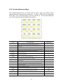
1
resistance of the current carrying leads. The Theory of Operation chapter 4 section 1 will
illustrate how the 4-wire principle is used to eliminate lead, wire, and contact resistances as
potential error sources.
3.3 Rear Panel
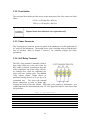
The rear panel of the 4176 may vary from unit to unit according to the optional features
installed. This section of the manual refers to the standard model without any optional
features or modifications. If the 4176 that you are using features terminals or connectors
not describe in this section, please refer to chapter 9 of this manual for addendums that
reference the particularities of your model.
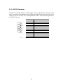
We will now outline the use of each of the rear panel controls and connectors.
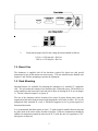
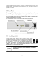
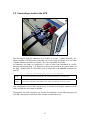
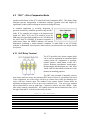
Figure 10 - 4176 Standard Rear Panel
3.3.1 Line Voltage Switch
The line voltage switch allows the user to select the power settings
according to the local AC line voltage. By sliding the switch upwards, the
number 115 will appear on the switch. The instrument is now configured
for line voltages of 115VAC ± 10%. By sliding the switch downwards,
the number 230 will appear. The instrument can now be used with line
voltages of 230VAC ±10%. Prior to powering on the ohmmeter it is conscious to verify
that the switch is set for the correct line voltage.
Selecting the incorrect line voltage setting may cause damage to
the instrument!
15