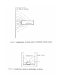
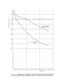
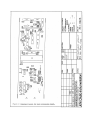
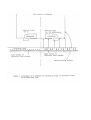
1
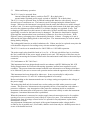
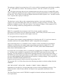
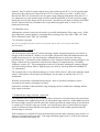
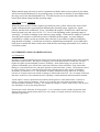
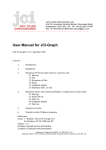
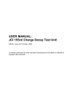
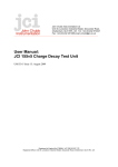
OOO
OOO
OOOOO
OOOOO
OOOOO
OOOOOOOOOO
OOO OOOO
OOOO
OOO OOOO
OOO OOOO
OOOO
OOO
OOOOOOOOOO
OOO OOO
OOOOOO
OOO OOO
OOOO
OOO
OOO
OOOOOO
OOOOOO
OOO
OOO
OOO
OOOOOOO
OOOOOOO
John Chubb
Instrumentation
Unit 30, Lansdown Industrial Estate, Gloucester Road,
Cheltenham, GL51 8PL, UK. Tel: +44 (0)1242 573347
Fax: +44 (0)1242 251388 email: [email protected]
________________________________________________________________________________________
USER MANUAL FOR ELECTROSTATIC FIELDMETER JCI 111
UM111 issue 13 - January 17, 1993
Contents:
1.
INTRODUCTION
2.
PRINCIPLES OF INSTRUMENT OPERATION.
3.
SPECIFICATION FEATURES.
4.
OPTION FEATURES
5.
POWER SUPPLY AND BATTERY CHARGING ARRANGEMENTS.
5.1 Mains and battery operation
5.2 Conformance to IEC 348
6.
SIGNAL OUTPUT CONNECTIONS.
7.
USE OF INSTRUMENT.
7.1
Earthing.
7.2
Zero reading.
7.3
Instrument support and mounting.
7.4
Unsuitability for use in flammable atmospheres
7.5
Operational checking
7.6
Response to alternating electric fields.
7.7
Settable alarm facility - Option A
7.8
RS423 communications interface - Option C.
7.9
Fast response - Option F
7.10 Manual/auto range selection - Option M.
7.11 Timer circuit - Option T
8.
INTERPRETATION OF OBSERVATIONS
8.1 Introduction
8.2 Basic aspects
8.3 Measurement of electric field
8.4 Measurement of potential
8.5 Measurement of charge
8.6 Measurement of surface charge density.
8.7 Measurement of static charge dissipation
9. FIELDMETER SET UP AND CALIBRATION
9.1
Principal instruments and facilities required
9.2
Basic electrical cheeks
9.3
Preparation for general set up and calibration
9.4
Set up of DVM section
9.5
Set up of angular alignment of chopping vane
9.6
Adjustment of phase sensitive detector
9.7
Set up sensitivity
9.8
Calibration
9.9
Fast response and long life instruments
9.10 Signal noise and variation of zero setting.
USER MANUAL FOR JCI 111
A versatile, high performance instrument for the measurement and monitoring of electric fields
from static charges and surface potentials.
1. INTRODUCTION
The JCI 111 is a 'field mill' type electrostatic fieldmeter providing auto-ranging sensitivities of
2, 20, 200 and 2000 kV m-1 FSD. Measurements are displayed on a 3½ digit LCD with polarity
and low battery indication. Surface potentials can be measured to a volt at a separation distance
of 90mm (3 1/2") and potentials of 50 volts can be observed a metre away. This performance in
a compact and lightweight unit provides the capability needed for the easy and reliable
investigation of static problems in a wide variety of industries - and is specially relevant for
studying the low levels of static which present risks in the semiconductor and microelectronics
industries.
The instrument can be operated from internal batteries or from the mains supply. It includes
integral battery charging facilities. An analogue signal output of electric field reading and range
is provided for chart recording and long term monitoring applications.
The bayonet pin mounting arrangement around the sensing aperture provides easy attachment
for a Faraday Pail (JCI 151) for measuring charge on small objects, a Zero Check Chamber (JCI
152) or Voltmeter Adaptors (JCI 156, 158) for zero current drain measurement of discrete
voltages. Options, such as computer linkage, are available to broaden the range of application of
the basic instrument and to match various special modes of operation.
2. PRINCIPLES OF INSTRUMENT OPERATION
The basic principle of 'field mill' operation is that when the instrument sensing surface is
exposed to an electric field a charge is induced in proportion to its' area and the strength of the
field. With a defined capacitance between the sensing surface and earth this charge appears as a
voltage which is presented to a high input impedance amplifier to generate a signal directly
related to the electric field. Because the sensing surface and the input connections always have
some finite leakage resistance, if left to itself the charge on the sensing surface will leak away.
However, by chopping the electric field with a rotating earthed vane in a time-scale which is
shorter than the RC leakage time constant of the sensing surface and the amplifier input circuit,
an a.c. signal is generated whose peak to peak amplitude accurately relates to the strength of the
source electric field. This a.c. signal is then amplified and rectified to produce an output directly
proportional to the strength of the observed electric field. The polarity of the source electric
field is obtained using a secondary chopping vane to generate a signal that drives a phase
sensitive detector for rectification of the a.c. signal. Phase sensitive detection also provides
good immunity to low frequency noise and to alternating fields that are not harmonically related
to the chopping frequency. With this 'field mill' approach the input time constant of the
instrument is infinite and the noise low. This means that 'field mill' instruments such as the JCI
111 have a stable zero and offer high usable sensitivity. The instrument can hence be used for
both short term investigatory studies and for long term continuous measurement and monitoring
of electrostatic conditions.
3.
SPECIFICATION FEATURES.
Sensitivity ranges:
- 2, 20, 200, 2000 kV m-l full scale, auto-ranging
Accuracy and linearity: - within +1% of range full scale on display and on
direct analogue buffered signal output.
- Zero offset stable long term within + 50V m-1
- Noise below +10V m-1
Controls:
- 3 position slide switch for operation by batteries or
integral mains power supply
- slide switch for 10mA battery recharging.
- screwdriver zero set adjustment.
Display:
- 3½ digit liquid crystal display of electric field
as kV m-1, with display of polarity and indication
of battery low condition.
Signal outputs:
- signal outputs via 4 pin connector pin 1: earth;
pin 2: electric field analogue signal (+2.0 V FSD);
pin 3: sensitivity range (1/4, 1/2, 3/47or 1 volt);
pin 4: with Option A, 5 volt signal indicating
alarm state; with Option T, electric field signal
with superimposed pulses indicating operating range
(every 10 min) and full scale calibration (each
hour) with timing by quartz crystal.
Facilities:
- bayonet pin socket arrangement around sensing
aperture for easy mounting of additional units.
- A 1/4" Whit thread tripod mounting bush.
- two holes in the back panel for safety strap support
Operation:
- integral nickel cadmium rechargeable batteries, 100 mAh,
providing about 4 hours continuous operation
(about 2 hours with Option F).
- integral mains power supply - 24OV/3A 50Hz supply
(115 V/3A 60Hz alternative).
Battery charging:
- 10mA integral battery charger with led indicator.
1mA trickle charge while connected to mains supply
Earth Bonding:
- 'Durable Dot' earth bonding connector on back plate.
Packaging:
- in injection moulded case with foam inserts with
User Manual, mains lead and signal lead.
Calibration:
- the instrument is set up in manufacture on the basis
of measurements whose accuracy is traceable to NPL
standards. Formal Calibration and Calibration
Certificate available as extra.
Dimensions and weight: - 65 mm square by 240 mm long, 900 grams.
4. OPTION FEATURES.
Option A: The Alarm option gives visual and acoustic warning during the time when the electric field
observed is above a user settable alarm threshold level. The threshold level may be,set anywhere within the
dynamic range of the instrument - from say 100 V m up to 2 MV m This alarm facility is particularly useful
where it is necessary to monitor and/or control electrostatic conditions in manufacturing processes or in work
environments. The alarm gives immediate local warning of unacceptable conditions so that these may be
directly correlated with particular operational activities and appropriate remedial actions taken. A signal
output of the alarm state is provided via the 4 pin connector.
The alarm level is set with a 4 position slide switch and a potentiometer in the bottom surface of
the fieldmeter. A key button is provided for temporary alarm buzzer muting.
Option C: Integral RS 423 communications interface for linking electric field measurements to
microcomputer via a serial data port (RS 232). Useful for data logging, correlation of
observations to other plant operating conditions and for process control. A 25 way D type
connector is mounted in the bottom plate. Operation at 9600 baud gives up to 400 12 bit
resolution readings per sec. Software for operation on IBM PC and compatible microcomputers.
Option F: Fast response for following rapid electric field changes.
Response time below 3 ms on the analogue output signal which enables 50 and 60 Hz signals to
be monitored. Useful in high speed process control applications. This Option includes the
proprietary Ibrushlessl fieldmeter design arrangement (Option L) and the Manual/Auto range
selection (Option M)
Option L: proprietary Ibrushlessl arrangement for long term continuous measurements of
electric fields
Option M: Additional 3 position slide switch in back panel providing manual selection of
sensitivity as alternative to normal auto-ranging. Useful where static conditions may exhibit
sudden short term excursions as it enables the short term upset of observations immediately after
range changing to be avoided. Automatic range change/range hold/range scan. If the instrument
is switched off in the 'hold' state then operation will restart with the same sensitivity setting
when switched on again.
Option T: Quartz crystal timer circuit providing superimposed time reference pulses on second
electric field output signal to indicate sensitivity range, zero setting and full scale calibration.
Useful for long term monitoring as all relevant information on a single chart record.
5.
POWER SUPPLY AND BATTERY CHARGING ARRANGEMENTS.
5.1
Mains and battery operation
The JCI 111 may be operated from:
internal rechargeable battery (switch to 'BATT' - B on back plate.)
nternal mains regulated power supply (switch to 'MAINS' - M on back plate).
The JCI 111 may be operated from it's internal rechargeable batteries with capacity for up to
about 4 hours of continuous use. The batteries can be recharged using the internal mains
charger. Whenever the instrument is energised from the mains the batteries are trickle charged
at about 1 mA. For more rapid charging the slide switch at the bottom of the back plate may be
moved to the rightmost position (marked C) to initiate charging at a regulated 10 mA. Full
recharging of the batteries at this current is achieved in 14 hours and this time should not be
appreciably exceeded or the batteries may be damaged. The batteries should not be charged
again until the instrument has been operated on it's batteries for at least a few hours. With
Option T battery recharging time is automatically limited to 14 hours. Charging at 10 mA is
indicated by the light emitting diode on the back plate. The instrument may be used on 'mains'
during battery charging.
The rechargeable batteries are nickel-cadmium cells. If these need to be replaced at any time the
cells should be disposed of according to any relevant national regulations.
The JCI 111 can be set in manufacture for 24OV/50Hz or 11SV/60Hz operation.
The mains supply plug should be fused at 1A or 3A. A 250 mA quick blow fuse is wired into
the 'line' connection on the power supply printed circuit card. The integrity of this fuse may be
checked by measuring the resistance between the line and neutral connections at the mains input
connector.
5.2 Conformance to IEC 348 Class 1.
This instrument has been designed and tested in accordance with IEC Publication 348:1978
'Safety Requirements for Electronic Measuring Apparatus' and has been supplied in a safe
condition. The present instruction manual contains some information on warnings which have
to be followed by the user to ensure safe operation and to retain the apparatus in safe condition.
This instrument has been designed for indoor use. It may occasionally be subjected to
temperatures between +5C and -10C without degradation of its safety.
Before switching on the instrument make sure its voltage setting corresponds to the voltage of
the power supply
The mains plug shall only be inserted into a socket outlet provided with a protective earth
contact. The protective action must not be negated by the use of an extension cord without a
protective conductor. Any interruption of the protective conductor inside or outside the
instrument or disconnection of the protective earth connection is likely to make the instrument
dangerous. Intentional disconnection is prohibited.
When the instrument is connected to a mains supply internal connections may be live and the
opening of covers or removal of parts is likely to expose live parts. The instrument shall be
disconnected from all voltage sources before it is opened for any adjustment, replacement,
maintenance or repair.
Any adjustment, maintenance and repair of the opened instrument under voltage shall be
avoided as far as possible and , if inevitable, shall be carried out only be a skilled person who is
aware of the hazard involved.
Make sure that only fuses of the required 25OV and 25OmA ratings are used for internal fuse
replacement. The use of makeshift fuses and the short circuiting of fuse connections is
prohibited.
Whenever it is likely that the protection has been impaired the instrument shall be made
inoperative and be secure against any unintended operation. The protection is likely to be
impaired if the mains connection sockets are cracked, if the mains cable is damaged or if the
mains cable has been pulled from its connectors.
6. OUTPUT CONNECTIONS.
The JCI 1ll fieldmeter provides a buffered output of the analogue signal presented to the internal
digital voltmeter and displayed on the LCD. This analogue signal may be displayed on an
ultraviolet or paper chart recorder. This signal is output via pin 2 (red lead) of the 4 pin
connector in the back plate as a bipolar analogue signal (+2.0 V FSD) with pin I as signal earth
(black lead). The output impedance is I k ohm. Pin 3 (blue lead) provides continuous indication
of the sensitivity range of operation as a buffered signal of about 1/4, 1/2, 3/4 or 1 volt. Pin 4 is
only connected with Options A and T - the alarm circuit and timer circuits.
7.
USE OF INSTRUMENT.
7.1 Earthing
The fieldmeter needs to be earthed (or held at a defined potential) if the readings are to be
interpreted and used with confidence. The instrument is best earth bonded by connecting the
'Durable Dot' ESP earth bonding point on the back plate of the instrument to a suitable earth
point. Alternatively, the instrument may be earthed via the mains power supply connection or
via mechanical mounting of the front plate.
7.2 Zero reading
In normal operating conditions the reading in the absence of any applied electric field will
remain below +50 V m. Checking the zero reading needs to be done with some care because the
high sensitivity of the instrument makes it susceptible to even very low levels of charge or
voltage on surfaces close to the sensing aperture. Thus different apparent zero readings will be
observed if the instrument is rested directly against different metal surfaces. This is because of
the different electrochemical potentials of the surfaces of different materials. Contamination or
corrosion on such surfaces may generate additional effects. The best way to check the zero
reading of the fieldmeter is to mount it to 'look' into a closed clean metal chamber where the
nearest surface is at least 50 mm away from the sensing aperture with this chamber connected to
the fieldmeter earthing point. A Zero Check Chamber JCI 152 is a convenient unit for easy
checking and setting of zero.
The zero reading exhibited by the fieldmeter may be affected if contamination is present on
surfaces in and around the sensing aperture. Care should be taken not to handle the rotating
chopper or the sensing surfaces. So long as the zero reading of the instrument is stable and
adequately small it is satisfactory just to subtract the zero reading from the observations made.
If however the zero reading gets too large or is unstable (for example becomes very susceptible
to
breathing into the sensing aperture) then it may be desirable to carefully wash the sensing
aperture region (for example using isopropyl alcohol) and/or to readjust the zero setting.
7.3 Instrument support and_mounting
The side extrusions of the JCI 111 are designed for comfortable hand support so the instrument
can be used easily for handheld investigatory studies. Two 3 mm holes are provided on either
side of the base flange of the back plate of the instrument so a safety wrist or neck strap may be
connected.
The back plate of the instrument has a 1/4" Whit threaded insert in the base flange so the
instrument may be mounted from a standard photographic tripod for extended duration studies.
The fieldmeter may be mounted from the bayonet pins socket arrangement around the sensing
aperture. The bayonet pins are mounted into M3 tapped holes on a 62.62 mm pcd around a 47
mm diameter aperture. For flush mounting of the sensing aperture the plate thickness needs to
be 3.0 mm.
7.4 Unsuitability for use in flammable atmospheres.
Although the JCI 111 electrostatic fieldmeter is of low power consumption it is not BASEEFA
certified as suitable for use in flammable atmospheres.
7.5 Operational checking
The JCI 111 fieldmeter has proved reliable and stable in extended operation. It is however
recommended that if the instrument is being used in critical applications that the zero reading
and the calibration be checked occasionally. As noted above the zero reading is susceptible to
contamination and while experience is gained in the use of the instrument in particular
applications it is recommended that the zero setting should be checked at least once a week.
Calibration should not need checking more often than every 6 to 12 months. Instrument
sensitivity may be checked quite simply at any time with the instrument bonded to earth and
held 90 mm away from a large plate (say 1/2 m square) at a defined voltage. The reading on the
LCD should correspond to the plate voltage divided by 50 - i.e. a reading of 1.000 should be
obtained with a plate voltage of 50 volts at 90 mm separation.
7.6 Response to alternating electric fields
The chopping frequency during operation of the standard JCI 111 is about 180 Hz - but may fall
to around 150 Hz by the time the batteries have nearly run down. With this chopping frequency
there is no significant interference to either the analogue output signal or the LCD reading until
the signal frequency reaches the chopping frequency or an odd harmonic to produce beat signals.
Fieldmeter operation is insensitive to basic mains frequency signals.
The response of the analogue signal output on the standard JCI 111 to alternating signals is
down to a half at 5 Hz and is very small by 20 Hz.
7.7 Settable alarm-facility - Option A
The alarm threshold is set with the controls accessed through the bottom cover of the fieldmeter.
A 4 position slide switch allows selection of the sensitivity range - range I is the most sensitive
(2 kV m-1) and range 4 the least sensitive (2000 kV m-1). The potentiometer provides setting
within the selected range - clockwise rotation for a higher level. The threshold setting applies
for both polarities ~ and the setting is reasonably polarity symmetrical. The alarm level may be
set using a piece of charged plastic to generate the desired level of field as indicated by the
display and then adjusting the potentiometer accordingly. If the fieldmeter sensitivity range is
set 2 or more steps higher than the alarm set range then the alarm sounds.
When the observed electric field increases above the set threshold the light emitting diode and
the piezoelectric buzzer in the bottom surface are activated and pulse on and off at about 1 Hz.
These warnings remain activated while the electric field remains above the set threshold level.
A key button is provided to allow muting of the acoustic warning until the next time the electric
field rises above the set threshold. While in the alarm state a steady output signal of about 5 V is
provided on pin 4 of the 4 pin output connector on the back panel. Use of the muting button
does not affect operation of the led warning or the alarm output signal. If the alarm warning is
not required to be active the slide switch may be set to range 4 and the potentiometer turned
fully clockwise.
7.8
Operation with RS423 communications interface - Option C
7.8.1 Introduction
The RS423 interface of Option C enables observations of electric field to be transferred directly into
an IBM PC or compatible microcomputer for data storage, alarm threshold comparison, process
control and/or data analysis. This requires operation from the mains supply.
7.8.2 Allocation of pins on 25 way 'D' type connector.
Allocation of pins on 25 way 'D' type socket connector on back cover and on 9 way D type connector
of serial data port of IBM PC or compatible microcomputer:
25 way D
1
2
3
4
5
6, 8, 20
7
20
type
frame ground
Transmit data TD
Receive data RD
RTS
CTS
linked together
signal ground
9 way D type
5 (cable screen)
3
2
7
8
1,6
1
4
7.8.3 Cable
The cable should be a 'straight through' (DCE/DTE) multicore cable with no crossovers - and
preferably screened.
With the external RS423 communications unit it is necessary to link pins 1 (earth), 2 (signal) and 3
(sensitivity) between the 4 pin connector on the unit and the 4 pin connector on the JCI 111 fieldmeter.
7.8.4 Data communication arrangements
Transmission of an RTS signal from the computer initiates 12 bit analogue to digital conversion of the
fieldmeter signal. The results of this conversion are communicated back directly to the computer as
two bytes of information. The first byte contains the least significant 8 bits (the LO byte). This is
followed immediately by the second byte which contains the remaining 4 bits of the 12 bit conversion
with bits 5 and 6 as a 2 bit number giving the sensitivity range of the fieldmeter.
The analogue to digital conversion factor of 5.0 volts as 4096 is arranged to provide bipolar capability
of + 2.5 volts with zero at 2048. The sensitivity is hence 1.2207 mV (1.2207 v m 1) per bit.
The 12 bit data conversion and two byte communication proceeds on receipt of a single RTS signal
with no additional signalling from the computer and no preceding transmission of a CTS signal from
the interface. This is done to provide the highest data transfer and acceptance rate. The data structure
uses 1 stop bit and no parity on each byte.
7.8.5 Data rate
The baud rate is set by links on the communications interface circuit card at 9600 baud. The
software can accept and handle data at this rate with direct writing to memory can achieve 400
fieldmeter readings a second. This gives about 2.5 ms between readings. In the program JCI111
the rate of reading is limited by arrangements for screen display.
7.8.6 Microcomputer
IBM PC or compatible microcomputer with CGA or better graphics capability.
Operation of the software does not depend on whether a fast or slow processor clock is used but operation will be a bit quicker with a higher clock rate.
7.8.7 Program structure and operation
The software for the transfer, storage and analysis of data from the JCI 111 has been written in
assembler and Pascal for standard IBM PC and PC compatible microcomputers.
After connecting the JCI 111 fieldmeter to the computer via the serial data port and with the
fieldmeter operating from the mains supply start program operation by typing JCI111. The
initial menu allows selection of COMI or COM2. If COM1 yields a data communications
failure then COM2 should be tried.
In operation the screen display shows a continuously scanning table of fieldmeter readings in kV
m 1 and these same readings are appended to a file LOGFILE on the same disc drive as the
program. The date and time are written at the beginning and end of each period of data filing. A
file SETUP provides simple opportunity to set the numbers of observations which are averaged
for each reading displayed and recorded and the frequency of taking readings. (The program will
fail unless files SETUP and LOGFILE exist).
Program operation may be halted at any time by pressing Ctrl C.
The program JCI111 in Turbo Pascal uses the following procedures to obtain readings from the
fieldmeter:
CRT DECAYINIT DECAYHD GRAPH CLKINT HEAD SERIALTP
Opportunity is provided for 1 bit logic data input via pin 4 of the 4 pin Bulgin connector. This
will activate bit 6 of the HI byte and this will require some appropriate adjustment of the
software.
The Turbo Pascal source code JCIIII.PAS is supplied so that the software may be adjusted to
user requirements.
Option C may be used for simple charge decay observations by the JCI 111 to be recorded and
analysed by the software developed for the JCI 155 Charge Decay Test Unit - eg DECAY15.
Because the DECAY software does not recognise range changing information from the JCI 111
it is important to use the manual range selection switch (Option M) to fix the sensitivity range
during the period of the charge decay observation. Alternatively the data recorded in LOGFILE
may be 'imported' directly as numbers into a spreadsheet program such as Lotus 123 for
numerical processing.
7.8.8 Runtime errors
Although the software has been well tested it is possible that Runtime Errors may occur. If this
does happen the system should be 'reinitialised' by pressing at the same time CTRL, ALT and
INS or Irebooted' with CTRL, ALT and DEL.
7.8.9 Software copyright
The general copyright of the above software for operation with the JCI 111 is owned by John Chubb
Instrumentation.
7.9 Fast response ~ Option F.
The fast response with Option F is achieved using a higher chopping frequency provided by a
chopper with 20 instead of 3 blades, use of a higher speed motor and with enhancements to the
signal processing circuit. An electronically commutated motor is used to provide long
operational life. Construction of the fieldmeter is also changed in that the rotating chopper is no
longer earthed but any potential developed on the chopper is compensated by a secondary
fieldmeter system (16). This arrangement avoids wear of brushes earthing the rotating chopper
and reduces drag but may allow a slightly larger zero drift on warm-up than with standard JCI
111 instruments.
The response time to step function changes of electric field is about 3 MS on the analogue signal
output. Observations via the liquid crystal display are the same as with the basic JCI 111
instruments.
With the electronically commutated motor about 1 hour of operation on batteries can be
expected before battery recharging is needed.
Option M is included so that automatic range changing can be avoided when studying sudden
large signal excursions.
7.10 Manual/auto range selection - Option M.
The additional slide switch in the back panel allows selection of operation between normal autorange changing in the rightmost position (A) and manual range selection. In the middle position
the current range setting is held (H) and in the leftmost position the range setting is incremented,
or scanned (S), at about I range per second. Any desired range may be selected by moving the
switch to leftmost position and then moving the switch back to the middle position when the
desired range is accessed.
If the fieldmeter is switched off while in the hold (H) state the same sensitivity range will be set
when it is switched on the next time. The range indicating signal at pin 3 of the 4 pin connector
operates as normal with option M.
When manual range selection is used in conjunction with the alarm circuit (option A) the alarm
will be activated continuously if an operating range is selected two decades or more higher than
the range set for the alarm threshold level. This advises the user to reconsider the relation
between the alarm setting and the operating range.
7.11 Timer circuit - Option T.
When the timer circuit is fitted a signal is provided on pin 4 (yellow lead) as the electric field
signal with timed pulses superimposed indicating the operating range, signal zero, signal
polarity and full scale calibration. Every 10 minutes the output is switched for a short interval
between signal zero and a level of 1/4, 1/2, 3/4 or I volt depending on the operating range of
sensitivity. A similar switching occurs after any range change. Each hour the output is switched
from full scale negative to full scale positive to identify the hour point. As pulse timing is
controlled by a quartz crystal an accurate time reference is provided for signal correlation in
long duration recording. A multi-turn screwdriver adjustment potentiometer is provided in the
back plate to enable the chart recorder trace with the time and range information to be scaled to
convenient values.
8. INTERPRETATION OF OBSERVATIONS.
8.1 Introduction.
Insulating and semi-insulating materials acquire electrostatic charge when rubbed against other insulating
materials or against metals. The degree of charging varies with the materials involved and is usually
higher for higher speeds and higher pressures of rubbing. Such 'tribocharging' can present risks of
ignition of flammable gases, shock risk to personnel, attraction of dust and debris, cling of thin films,
damage to semiconductor devices and upset operation of microelectronic systems. The problems caused
by 'static' and they may be controlled are discussed in published papers and a number of Standards
documents (eg references 1-12). The quantities of charge, amounts of energy and levels of voltage
relevant are in general lowest in relation to damage to semiconductor devices. So it is usually in this area
that there are the most critical demands on the capability of instrumentation and measurement methods.
"Electrostatics" relates to phenomena associated with the presence, rather than motion, of electrical
charge. Charge is the key parameter. However, it is usually more convenient to measure features
associated with the influence of charge - for example the voltages or electric field created. This involves
less disturbance to the system being measured.
Electrostatics seems "difficult" for many people - so it is sensible to retain a healthy skepticism when
making electrostatic measurements and wise to cross cheek even simple and basic observations with
alternative approaches.
8.2 Electric Field Measurement
Fieldmeter measurements relate to the electric field in the vicinity of the sensing aperture and
the response to this electric field is established by calibration with the fieldmeter sensing
aperture mounted flush with the earth plate of a large parallel plate calibration rig. The size of
the plates needs to be large in comparison to the spacing to ensure a uniform electric field in the
region of the plates where the fieldmeter aperture is located. Fieldmeter calibration was
described at the International Electrostatics Conference in Oxford April 1987 (13).
For some measurements the fieldmeter may be mounted flush with a conducting boundary. In
this case the fieldmeter is used in the same way as when it was calibrated and the readings
obtained may be interpreted directly in terms of the local electric field at the boundary.
However, in many instances the fieldmeter is used by itself - in particular for handheld studies.
In such use, as the fieldmeter is brought towards a charged conducting or insulator surface there
is a convergence of electric field lines towards the sensing aperture region of fieldmeter because
of it's relatively small cross section. This is illustrated in Figure 1. The local electric field at the
sensing aperture is increased over that which would apply in a plane parallel field geometry.
The factor by which readings need to be multiplied to give a value corresponding to a plane
parallel field situation varies with gap is shown in Figure 2.
With sensitive fieldmeters care needs to be exercised with zeroing (as noted in section 7.2
above) to avoid problems with surface trapped charges and contact potential effects. The best
approach is to mount the fieldmeter to 'look' into a clean closed metal chamber in which the
nearest surfaces are at least 50 mm away from the sensing aperture of the instrument (eg JCI 152
Zero Check Chamber).
When fieldmeters are used for hand held investigatory studies care needs to be taken to ensure
that the instrument is properly earth bonded (as noted in section 7.1 above). Metal bodied
instruments may have a good connection to the operator's hand - but no assumptions should be
made about the effective conductivity of footwear or flooring.
8.3 Measurement of potential
The electrostatic potential of a surface may be obtained by observing the electric field generated
at a nearby earthed fieldmeter. However care is needed with small structures to avoid the
proximity of the fieldmeter affecting the capacitance of the body as this will depress the
potential to be measured. Care may also be needed in interpretation of readings where the size
of the body or area of charge is not too large in comparison to the size and spacing from the
sensing aperture.
The electrostatic potential of a person may be measured using an earthed fieldmeter to observe
the field at a convenient distance from the person's hand. A hand is preferable to clothing to
avoid the risk of susceptibility to any localised surface charges on clothing material.
Alternatively, the person may measure his own potential by holding the fieldmeter a known
distance from an earthed surface. In either case the potential is obtained as the reading
multiplied by the distance and by the appropriate correction factor from Figure 2. With the JCI
111 fieldmeter at a separation distance of 90 mm the potential of a surface in volts is obtained as
the LCD reading multiplied by 50 (the distance of 90 mm X 0.56 - the 'correction factor' for this
distance). Thus a reading of 1.000 at 90 mm corresponds to 50 volts - and measurements
may readily be made to a resolution better than a volt.
The potential of isolated metal structures may be measured using the ‘electrostatuc voltmeter'
approach - using for example the JCI 156 or JCI 159 Voltmeter Adaptors with the JCI 111
fieldmeter. The Adaptor provides a shielded enclosure within which a smooth boundary
electrode is mounted in a mechanically stable arrangement in relation to the fieldmeter sensing
aperture. The design is arranged so that there is a simple relationship between the voltage on
the electrode and the reading of the fieldmeter. While the capacitance of the electrode and
connection is low some charge sharing will occur and this may affect the potential observed.
8.4
Measurement of charge
The standard method for measuring nett electrostatic charge on an item is to use a Faraday Pail
The arrangement is illustrated in Figure 3.
With this approach the nett quantity of charge introduced into the volume of the conducting
pail appears as induced charge of the same sign and magnitude on the outside of the pail,
providing all the charge introduced couples to the inside of the pail. it is not necessary that the
charge introduced is conducted to the inside walls of the pail - so the pail is equally effective
for charged insulating materials as for conductors.
The charge induced on the outside of the pail may be measured by a suitably sensitive charge
integrating circuit or with the pail insulated from earth using a fieldmeter to measure the
voltage to which the pail is raised in relation to it's capacitance. This is the approach adopted
with the JCI 151 Faraday Pail adaptor used in conjunction with the JCI 111 fieldmeter.
8.5 Measurement of surface charge densities
Where a charged web of insulating material is fairly remote from any nearby earthed surfaces
there is an electric field E normal to the surface and related to the algebraic sum of the charge
densities Q, and Q2 on the two surfaces of the web as:
E = (QI+Q2)/ (2eo)
where e. is the permitivity of free space 8.854 X 10⁻¹² F m-1. If an earthed fieldmeter is
mounted reasonably close to a section of the web and if this is much closer than any other
earthed surfaces, then all the charge on the web will couple to the fieldmeter. If the fieldmeter
is mounted within a plane surface several times larger than the spacing to the web, then the
field between the web and the fieldmeter will be essentially uniform and relate to the surface
charge densities as:
E = (Q1+Q2) /(e 0)
Charge densities residing on individual sides of an insulating web may be monitored using a
sensitive fieldmeter to measure the electric field from the web as the web passes over an
earthed roller. The charge on the surface contacting the roller will be so closely coupled to the
roller surface that it will produce little external field - but the charge on the outside surface will
not be so closely coupled and will produce a electric field able to be measured by a nearby
electrostatic fieldmeter. For a web of thickness t (m) and of permittivity k and the fieldmeter
sensing plane at a distance d (m) the charge density on the web Ql will relate to the observed
electric field E as:
E = Q, t/(k eo d)
A charge density of say l*10- 6 C m- 2 on a web of 100 micron thickness and permittivity k=2
lying on an earthed surface will give a field of 564 V m at an earthed sensing surface 10 mm
away - a modest field strength but quite sufficient for proper measurement.
8.6 Measurement of static charge dissipation.
Traditionally the ability of materials and surfaces to dissipate static charge has been assessed
by measurement of resistivity - bulk and surface. This is not a satisfactory guide to the
timescale for charge dissipation because with many practical materials the mechanisms of
charge migration are not uniform over the surface or volume of the material and vary with the
residual electric field. The appropriate way to study charge dissipation is to deposit a localised
patch of charge on the surface to be tested and then to use a fieldmeter for non-contact
measurement of how quickly the potential of the charged patch decreases as the deposited
charge migrates away. This approach is used in the JCI 155 Charge Decay Test Unit (14, 15).
Charge decay measurement is described in a document being discussed by the International
Electrotechnical Commission committee SC15D considering Standards in Electrostatics (17).
The JCI 111 fieldmeter can be used very simply for qualitative assessment of the charge decay
characteristics of materials when the decay time is at least a few seconds. An area of the
material or installed surface is rubbed with a tissue or piece of teflon or polythene sheet. The
JCI 111 is laid onto the surface with the sensing aperture close to the area rubbed. The initial
fieldmeter reading and the rate of decrease will show very directly the degree of charging and
the rate of charge decay.
9. SENSITIVITY SET UP
The JCI 111 fieldmeter is carefully set up during manufacture. No adjustments should be
attempted unless suitable instruments and facilities are available to check the set up and
sensitivity of the instrument. The following notes describe procedures to set up the JCI 111
and set its sensitivity. The procedure to check calibration is described in Section 9.8.
The primary basis of setting sensitivity and measuring calibration is to establish a uniform
electric field between two large plane metal surfaces and to mount the fieldmeter sensing
aperture flush with one of these surfaces. For the electric field to be uniform and well defined
in the region around the mounting location of the sensing aperture:
a) the surfaces need to be large in comparison to the spacing between them so that the field in
the central region is not affected by fringing field effects or any external sources of charge so
that the value of the electric field may be accurately related to the separation gap and the
voltage difference.
b) the gap between the surfaces needs to be suitably large in comparison to
the size of the sensing aperture so that perturbation of the electric field in the vicinity of the
recess of the sensing aperture is localised and does not reach across the gap to the other surface.
Consideration of the above requirements has been published (13). It is found necessary for
calibration of JCI 111 type fieldmeters to better than 1% that the separation distance between
the plates should be more than 1.5 times the sensing aperture diameter with the surfaces having
a radial extent at least 15 times the sensing aperture diameter. This has been checked in
computer modelling calculations and, in practice, by looking at constancy of calibration as the
separation gap is increased.
The physical arrangement of components, test points and adjustment potentiometers for the
main processing board and for the power supply and timer board are shown in Figures 4 and 5.
Figure 6 identifies the use of the 17 leads of the flexible board to board connection.
9.1. Principal instruments and facilities required
- uniform electric field calibration unit. This may consist of a pair of rigid, flat and parallel
metal plates, for example at least 500 mm x 500 mm spaced a defined and stable distance apart,
for example 50.0 mm, with a 47 mm diameter hole in the middle of the top plate where the
metal thickness over a diameter of 95 mm is 3.0 mm so that the front of the fieldmeter lies just
flush with the underside of the plate. The lower plate needs to be insulated and protected to
that voltages up to 30 kV may be safely applied for establishing the higher value of calibrating
electric fields.
- regulated voltage sources of +2 V, +0-1 kV and +0-30 kV.
- voltmeters capable of measuring 2V, 1OOV, IkV and 3OkV to an accuracy better than +1%.
- oscilloscope with a sensing probe having an input impedance of 10 Mohms.
9.2 Basic electrical checks.
- remove back plate by the two M3 screws and slide out the top and bottom covers.
- energise fieldmeter circuits from own internal battery (if adequately charged) or from the
internal mains power supply (taking care to avoid touching or shorting exposed mains
energised connections).
- check at the board to board connection points on the lower, power supply, board
(see Figure 5) that the rail voltages of the internal regulated supply are +7.5 and -7.5 volts
(within + 0.5 V) and are free from noise and ripple. (Take care not to short rail to rail as this
may destroy to opto-sensor).
- check that the led indicating 'charging at 10 mA' illuminates when the charging switch is
moved to initiate charging.
- check the trickle charging voltages and currents, these should be about 19 V and 2.4 mA to
ground (the charging current to a fully charged battery will be about 1.2 mA).
- check the '10 mA' charging current to be correctly set by measuring the current to earth of
inter-board connection points 6 and 11 (see Figures 4 and 5) while the batteries are being
charged. The currents should be about 12 mA, the sum of the trickle and controlled charging
currents.
9.3 Preparation for general set-up and calibration adjustment.
- remove back plate of fieldmeter, slide out top and bottom covers. If it is desired to clean or
check the state of wear of the chopper earthing brushes or to adjust the phase sensitive detector
then it will also be necessary to remove the right hand side plate and fold out the power supply
and timer circuit card.Do not remove both side extrusions at the same time - always have one
extrusion in place to provide support for the main processor board from the front plate.
- if the fieldmeter is energised from it's rechargeable batteries then care must be taken to avoid
shorting out the supply rails during probing and
- the fieldmeter should not be energised from the mains during general set up and calibration
because of the shock risk from exposed connections on both the fieldmeter and the power
supply printed circuit cards.
9.4 Set-up of DVM section.
- with the end of R21 nearest to C13 grounded check that the LCD reading is 0.000. If not there
is a fault in the DVM circuitry.
- inject positive and negative voltages -1.90 to +1.90 to the end of R21 nearest C13 and adjust
RV9 so LCD reading corresponds exactly to injected voltage for both polarities and check at
lower voltages over range.
9.5
Set-up angular alignment of chopping vane. - connect oscilloscope probe to R16.
- either apply a positive potential to the plate of the calibrator facing the fieldmeter or bring a
positively charged body (a sheet of methyl methacrylate, 'Perspexl, charges up positively when
rubbed with a paper tissue) up in front of the Voltmeter sensing aperture. The signal at R16
should consist of negative half-cycle sinusoidal waves.
- if the chopping of the waveform observed at R16 occurs part way through the half-cycles or If
the waveform is composed of positive half-cycle waves then the fieldmeter should be switched
off and the right hand side extrusion of the instrument temporarily removed to gain access for
resetting the relative angle between the front and the secondary chopping vanes. The
grubscrew clamping the front chopping vane should be loosened slightly and the relative
angular positions of the front and rear rotor vanes re-adjusted until the signal at R16
corresponds to the desired pattern of exact half-cycle waveforms of negative polarity.
- carefully re-tighten the screw clamping the front chopping vane, check the waveform at TP3
and then replace the side extrusion.
9.6 Adjustment of the phase sensitive rectifier
- shield the sensing aperture of the fieldmeter (but do not have the shielding surface too close to
the sensing aperture) or, if using the calibrator, mount the fieldmeter on the calibrator and apply
zero voltage.
- temporarily earth TP3 and adjust RV1 so that the LCD reading is zero.
- mount the fieldmeter mounted on the calibrator and apply a voltage of at least 50 volts across
the plates.
- switch on the fieldmeter and connect an oscilloscope probe to R16 and examine the
waveform. Successive half cycles of the waveform should be of equal amplitude. If this is not
so, adjust RV12 to achieve this. If the signal observed is noisy it will be helpful to apply rather
higher voltages than 50 volts across the calibrator.
- check that the equality of amplitude of successive half cycles applies for the other polarity of
voltage on the calibrator plate.
9.7 Sensitivity setting.
- during sensitivity setting it is desirable to have to provide shielding of the sensitive
preamplifier circuits. A dummy cover may be used pierced with holes matched to the locations
of the various potentiometers (as shown in
Figure 4) to provide access for adjustment.
- if the fieldmeter is very out of adjustment then set RV8 to about the midtravel position,
otherwise proceed by just adjusting potentiometers RV3 to RV6.
- set the voltage across the calibrator to the value to be used for calibrating the top range. For a
calibrator pate gap of 50 mm 15 or 30 kV will be convenient - with the voltage chosen as a
convenient multiple of the actual gap in mm. Adjust RV6 to give correct reading on LCD.
- reduce the voltage carefully to a value corresponding to a reading of 110 kV m I on the top
range - without allowing the range to change down. (With a 50 mm gap this will be 5.50 kV).
Adjust RVI to achieve an LCD reading of 110. Take the calibration voltage back to the
maximum calibration figure and reset RV6. Iterate between these two levels until the readings
match at both points.
- short out the calibrator plates and adjust RV10 to give an LCD reading of zero.
- set the voltage across the calibrator to provide calibration fields preferably towards the top
value for each sensitivity range. The voltages listed below are based on use of a 50.0 mm gap.
Adjust the potentiometers as listed to obtain the desired readings on the LCD. Because the
setting of RV3 has some effect on the setting of RV4 it is appropriate to set up RV3 on the
most sensitive range before setting RV4. As the sensitivity ranges overlap check that the
fieldmeter is operating on the appropriate range before adjusting the potentiometers.
Reading
600.0
(110.0
110.0
1.900
19.00
Range
kV m-1
kV m-1
kV m-1
kV m-1
kV m 1
4
4
3
1
2
Calibration voltage
30.0 kV
5.50 kV
5.50 kV
95.0 V
950 V
Adjust Potentiometer
RV6
RVI)
RV5
RV3
RV4
- after setting the appropriate potentiometer on each range reduce the voltage across the
calibrator to the point at which the range changes automatically to the next most sensitive range
and check that this change occurs at LCD readings of 100 and 10.0.
- reverse the polarity of the voltage across the calibrator and check that the polarity and LCD
readings are correct. If not, check and readjust the angle of the chopper vane and/or the
balance of the phase sensitive detector as described in section 9.6 above.
- reposition the top and bottom covers and replace the back plate.
- run the fieldmeter for several hours or overnight in a zero field situation or on the calibrator
with the plates shorted out and record the observations on a chart recorder. Check that the
noise level of the output signal is suitably low and that the zero setting remains stable.
9.8 Calibration
Formal calibration of the sensitivity of the JCI 111 requires use of voltage and distance
measuring instruments which have been calibrated with accuracy traceable to National
Standards. The procedure and information to be recorded for formal calibration has been
described in a draft document prepared for the UK Working Party of International Technical
Commission Technical Committee SC15D (18,19).
9.9
Fast response and long life versions of JCI 111
For the fast response and long life version of the JCI 111 (options F and L)
The input amplifiers for the two fieldmeter sections are mounted on an annular circuit board
around the electronically commutated motor. The only adjustment available on this circuit
board is that for ‘charge balance' of the rotor. The charge balance should be checked and set
before checking or adjusting the
sensitivity of the instrument. The rotor should be earthed using a clean metal rod to connect
the rotor to the side of the sensing aperture. The fieldmeter should then be switched on and the
zero reading noted with the fieldmeter looking into a clean metal 'zero cheek chamber'. Switch
off the fieldmeter, add some charge to the rotor by touching it with a low voltage supply (for
example 9V relative to the instrument earth), switch on the fieldmeter and note the reading
when the instrument is again looking into the zero check chamber. The readings without and
with charge should be close. If they are not then the multi-turn potentiometer on the annular
circuit board should be carefully adjusted to achieve this. The charge balance setting should
not be affected by the zero setting adjustment.
9.10 Signal noise and variation of zero setting.
The output signal with the instrument in a zero electric field situation should be within about
+10 V m Higher noise levels are likely to be due to dirt in the area of contact of the gold wire
brushes used to earth the chopping vane behind the motor. The problem will probably be
solved by carefully cleaning the brushes and the local area of the motor shaft - for example
with the end of a matchstick dipped in isopropyl alcohol. Access for cleaning is obtained by
removing the back plate and one side extrusion.
As noted in section 7.2 the zero setting of the instrument on the most sensitive range can easily
be affected by contamination on surfaces in and around the sensing region. If the zero setting
is unstable or is rather susceptible to breathing into the sensing aperture then it is desirable to
carefully clean surfaces around the sensing region using, for example, isopropyl alcohol or
clean water.
REFERENCES.
1)
"Code of Practice for Control of undesirable static electricity"
BS 5958: Part 1:1980 General Considerations.
BS 5958: Part 2:1983 Recommendations for particular industrial situations.
2)
"British Standard Code of Practice for handling of electrostatic sensitive devices
" BS 5783: 1979
3)
Gibson, N. "Electrostatic hazards and their solution in the Chemical Industry"
International Workshop on Electrostatics, Oyez, Llandudno Sept 1983.
4)
Gibson, N. "British Standard Code of Practice for the Control of undesirable static
electricity" International Workshop on Electrostatics, Oyez, Llandudno Sept 1983.
5)
Gibson, N. "Evaluation of electrostatic hazards - A review of the present situation"
International Symposium on Electrostatics - Application and Hazards, Oyez,
Southampton, Sept 1984
6)
Loveland, R. J. "The management of electrostatic hazards: An overview" International
Workshop on Electrostatics, Oyez, Llandudno Sept 1983.
7)
Singh, S. "Hazards arising in the handling, transport and storage of powders"
International Workshop on Electrostatics, Oyez, Llandudno Sept 1983.
8)
Walmsley, H. "Electrostatic hazards and their elimination in the handling of petroleum
products" International Workshop on Electrostatics, Oyez, Llandudno Sept 1983.
9)
Wilson, N. "Problems in the manufacture and use of textiles" International Workshop on
Electrostatics, Oyez, Llandudno Sept 1983.
10)
Blythe, A. R. "Charge problems and their control in the plastics film industry"
International Workshop on Electrostatics, Oyez, Llandudno Sept 1983.
Davies, D. K. "Electrostatic damage to semiconductor devices
"International Symposium on Electrostatics - Application and Hazards”, Oyez,
Southampton, Sept 1984
11)
12)
Chubb, J. N. "The control of static electricity" Electrostatics Summer School 185"
University College of North Wales, 11 - 13 Sept 1985
13)
Chubb, J. N. "The calibration of electrostatic fieldmeters and the interpretation of their
observations" 'Electrostatics 187' Oxford, April 1987 Inst of Phys Confr Series 85 p 261
14)
Chubb, J. N. "Charge decay measurements for characterising static dissipative materials"
Dielectric Materials, Measurements and Applications, Univ Canterbury, June 1988. IEE
Confr Publ 289 p 283
15)
Chubb, J. N. "Instrumentation and standards for testing static control materials" IEEE
Trans on Industry Applications 26 6 Nov/Dec 1990 p 1182
16)
Chubb, J. N. "Two new designs of 'field mill' type fieldmeters not requiring earthing of
the rotating chopper" IEEE Trans on Industry Applications 26 6 Nov/Dec 1990 p 1178
17)
"Methods for testing insulating and static dissipative materials and surfaces by direct
measurement of the rate of dissipation of static charge" International Electrotechnical
Commission Technical Committee No 15: Insulating Materials. Draft to UK Working
Party April 1990.
18)
Calibration of electrostatic fieldmeter instruments for the measurement of electric fields"
International Electrotechnical Commission Technical Committee SC15D: Insulating
Materials. Draft to UK Working Party April 1990.
19)
Chubb, J. N. "Methods proposed for the calibration of static measuring instruments"
European ESD Symposium Eindhoven 4~5 Sept 1991
1
- ve supply rail from fieldmeter circuit
2
+ ve supply rail from fieldmeter circuit
3
OV logic
4
analogue signal from fieldmeter circuit
5
+ ve trickle charging, about 1 mA
6
+ ve 10 mA charging
7
+ ve line from mains power supply
8
0V, earth line
9
- ve line from mains power supply
10 'neutral' of mains power supply
11 - ve 10 mA charging
12 - ve trickle charging, about 1 mA
13 'line' of mains power input
14 analogue signal output
15 logic signal for range indication (bit 1)
16 logic signal for range indication (bit 2)
17 logic signal of range change enable
The above sequence is as viewed from the component side of the power supply printed circuit
card with the connection link to the left of the board - line 1 is then at the top and line 17 at the
bottom, as labelled on the board.
Figure 6: Connections via flexible board to board link.