1
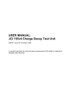
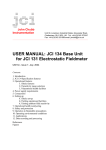
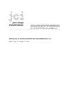
John Chubb Instrumentation Ltd
Unit 30, Lansdown Industrial Estate, Gloucester Road,
Cheltenham, GL51 8PL, UK. Tel: +44 (0)1242 573347
Fax: +44 (0)1242 251388 email: [email protected]
_________________________________________________________________________________
USER MANUAL:
JCI 191 CONTROLLED HUMIDITY TEST CHAMBER
UM191 – Issue 11: April 2008
Contents:
1. Introduction
2. Design features
3. Preparation for use
3.1 Standard JCI 191
3.2 JCI 191C
4. Connections
5. Testing
6. Operation
7. JCI 192 Dry Air Supply Unit
8. RoHS and WEEE Directives
9. Specification features
References
USER MANUAL:
JCI 191 CONTROLLED HUMIDITY TEST CHAMBER
To provide opportunity to measure the charge dissipation and
capacitance loading capabilities of materials under defined humidity
conditions with measurement of temperature and humidity. Humidity
can be controlled and measured from 65% down to below 15% RH.
Temperature up to 10°C above ambient. In the JCI 191C temperature
can be controlled to ±10°C around ambient.
1. INTRODUCTION
The ability of materials to dissipate static electricity quickly, as needed if static risks and
problems are to be controlled, can depend strongly on ambient humidity. The reason is that the
ease of charge movement depends on the amount of surface moisture that is adsorbed.
Humidity can also affect the ‘capacitance loading’ experienced by charge on the surface of
materials [1, 2]. Studies to compare the capabilities of materials and to judge their suitability
for practical applications need to be made under defined and measured conditions of
temperature and humidity. The JCI 191 Controlled Humidity Test Chamber provides simple
and easy to use facilities in which charge decay and capacitance loading measurements can be
made under set condition of humidity using JCI 155 charge decay test instrumentation with
various types of sample support [5,6]. The form and facilities of the standard JCI 191
chambers are shown in Figures 1 and 2.
The JCI 191 is available in two versions: the standard version in which the temperature
within the chamber can be controlled up to 10°C above ambient, and the JCI 191C version in
which the temperature can be controlled from 10°C below ambient to 10°C above. In both
cases the humidity can be controlled from below 15% to at least 65%RH.
2. DESIGN FEATURES
JCI 191 Controlled Humidity Test Chamber has internal dimensions of 600 x 800mm and
300mm high with a glazed lid that can be lifted up for loading and removal of samples. The
lid is hinged at its rear edge and can open 120º to stay in the open position. Two long sleeve
rubber gloves are mounted in the front side so that anything in the chamber can be reached for
handling or operation. The size of the chamber is adequate to take a good number of samples
and a JCI 155 Charge Decay Test Unit on a JCI 166 Sample Support or a JCI 176 Charge
Measuring Sample Support. A JCI 170 or JCI 173 Powder Sample Support may be used for
studies on powders. A JCI 150 Faraday Pail with JCI 178 Charge Measurement Unit may be
used for charge measurements on powders and small items.
The humidity in the chamber is measured using a semiconductor sensor (Honeywell HIH3160). This gives a linear response signal from 0 to 100%RH. This has been pre-calibrated at a
number of humidity levels against a Rotronic ‘Hygropalm’ temperature and humidity
measuring unit – and the humidity calibration of this is checked against reference salt
solutions. A semiconductor sensor is used to measure the temperature within the chamber. The
performance of these measurements is checked in situ by comparison to the Rotronic
‘Hygropalm’ temperature and humidity measuring unit. Observations of humidity and
temperature are displayed on separate 3½ digit LCDs on the control box mounted on the right
hand side of the chamber.
Humidity is controlled using a circuit that compares the observed humidity to a user set
level. If the humidity is above the set level then an electromagnetic airflow valve is opened to
provide a supply of lightly pressurised dry air into the chamber until the humidity has fallen
JCI 191 – September 2007
appropriately. To achieve levels of humidity above ambient, air from the chamber is
recirculated through a ‘water bubbler’ back into the chamber via a separate input port. The
dead band window of humidity control between too dry (amber LED) and too wet (red LED)
is about 2%RH. In the middle of the range a green LED shows satisfactory operation.
Dry air may be supplied as a pressure regulated flow from, for example, a cylinder of dry
compressed air or from a special air drier unit, such as the JCI 192 Dry Air Supply Unit. The
supply pressure needs to be a few p.s.i. pressure – up to 6 p.s.i. When using the JCI 192, with a
fairly modest gas flow capability, it is advantageous to have a small buffer volume (say 10l) in
the supply line to give quick response to any ambient air inflow leakage into the chamber that
may occur when hands are taken out of the gloves. Humidity changes is such events are
minimised by arranging the gas flow into the chamber to exit via a very flexible buffer
volume. This is a light plastic bag in a shielding box. Gas leaks out from this bag via a small
hole on the opposite side to gas entry. If hands are removed from the gloves the bag tends to
collapse to back-fill the chamber with air already at chamber controlled humidity conditions.
Temperature in the chamber can be controlled to a set level that is up to 10°C above the
surrounding ambient level. This is achieved in a similar way to the control of humidity with
heat input controlled by switching mains electrical power to two 50W lamps in a ventilated
shielding box in the chamber.
In the JCI 191C a 200W thermoelectric cooler unit is mounted into the left hand side panel.
The cooling performance of this is controlled using a servo control circuit that adjusts the
output of the power supply feeding the thermoelectric unit. With the additional thermal
insulation on all surfaces of the chamber this enables the temperature in the chamber to be
reduced to 10°C below ambient. Insulation on the walls and base of the chamber comprises a
7mm thick sheet of low density polystyrene within outer panels of 6mm PVC. The lid is
double glazed with a 6mm thick polycarbonate sheet. To minimise fan noise the power to the
internal and external fans is adjusted along with the power to the thermoelectric unit but
limited to a lower minimum level. Care should be taken not to obstruct free circulation of air
around the outside of the thermoelectric unit.
Air in the chamber is circulated by a continuously running the fan in the heater box and by
the small fan in the box mounting the humidity and temperature sensors. In the JCI 191C the
cooler side fan is also run at a modest level to help provide good stirring. These fans aim to
give uniform humidity and temperature conditions throughout the chamber. When preparing
for measurements with a JCI 155v5 Charge Decay Test Unit it is wise to ensure that air
circulation in the chamber can have access to the test aperture of the JCI 155v5 so chamber
conditions are also reliably achieved within the JCI 155v5.
With the additional thermal insulation of the JCI 191C the 100W heating enables
temperatures more than 15°C above ambient to be achieved and controlled in the chamber. To
achieve high humidities in combination with high temperature the water in the water bubbler
unit is heated by a heater resistor dissipating 14W. This additional heating is provided when
humidities over 45%RH are requested and when the ambient temperature around the chamber
is less than 35°C.
To avoid changes in conditions in the chamber from volume changes when hands are
entered and removed from the gloves a flexible plenum buffer chamber is provided at the back
of the right hand side panel. This comprises, within the mounting box, a light plastic bag
through which air input to the chamber flows out through a small vent hole. Any reduction in
pressure within the chamber, when hands are withdrawn from the gloves, collapses the bag to
backfill the chamber without drawing back in any outside ambient air.
1
JCI 191 – September 2007
3. PREPARATION FOR USE
3.1 Standard JCI 191
The JCI 191 is dispatched with the control panel for the right hand side packaged inside the
volume of the chamber. The knob to enable the lid of the chamber to be easily opened is
wrapped separately and is easily accessible through the open side of the chamber. This
package includes the screws for mounting the control panel to the right hand side of the
chamber. The first action is to find and take out this small package, fit the knob and open the
chamber lid.
The control panel has all its facilities pre-mounted and pre-connected. The panel is
wrapped for transport and after taking it out through the top of the chamber it is unwrapped.
The panel gasket is taped to the inside of the base of the chamber, and this should also be
taken out carefully.
The control panel is most conveniently fitted with the chamber standing on the floor with
the panel aperture end uppermost. Place the gasket in position in the recess around the
aperture, rest the panel on the gasket and align the screw and gasket holes and then insert and
tighten the 12 self-tapping screws to secure and seal the panel to the chamber.
The chamber can now be placed on a flat and stable working surface with the glove rings
facing towards the operator position and the lid opening from the hinge on the rear edge. With
the panel in position the earth bonding lead from the panel to the chamber case is secured with
the nut on the screwed pillar in the front right hand corner of the chamber base.
Three sealed holes are provided through which leads can pass into the chamber. These
might be an 18V output from a switched mode power supply for recharging batteries and
operating a JCI 155v5 Charge Decay Test Unit, an 8w mini-DIN to 9w D type connector lead
for linking a JCI 155v5 to an external computer for on-line operation and perhaps an 8w miniDIN cable from a JCI 176 Charge Measuring Sample Support for external display and/or
recording of charge measurements. These leads need to be fitted through the seals with good
sealing maintained. This may conveniently be done by taking out each of the grey bungs,
cutting of the tip end then slitting down one side to the central hole, passing the cable through
the middle area and then replacing to seal into the panel mounting hole.
In preparation for testing and operation the water bubbler bottle is filled with clean water
to the mark about 15-20mm below the screw lid. This is easily achieved by filling through the
conical top hole in the mounting block. A 10-20ml syringe provides is a simple way to add
water. If the water kevel is too high there is a danger that water droplets may be thrown into
the chamber – which is not good! Dry air is supplied through a 6mm diameter plastic tube
connected via the push-in pneumatic connector on the upper side of the Control Box.
3.2 JCI 191C
The JCI 191C is shipped fully assembled. This avoids the user needing to mount any panels
or make any electrical connections. Everything is ready to go once water has been put into the
water bubbler bottle. The assembled chamber is quite heavy so care is needed in unpacking
and handling.
4. CONNECTIONS
The mains power supply input to the control box is via an IEC connector fused at 2A with
an anti-surge (slow blow) fuse (20mm long 5mm dia). There is a spare fuse held in the fuse
carrier. There is an additional fuse holder in the side of the control box y the IEC input
connector. This provides protection in the event of failure of the heating lamps resulting in a
short circuit. This fuse is a 1A 20mm fast blow fuse.
2
JCI 191 – September 2007
The power supply input needs to be 240V to run the heating lamps and the water bubbler
pump. If the available mains power supply is 110V it will be necessary to use an external
110V/230V 100VA adaptor unit.
Three blanked-off glands are provided in the right hand side panel for user cables into the
chamber. These may be used, for example, to provide:
- 18V input from an external switched mode power supply for mains operation
and/or battery recharging with a JCI 155v5 Charge Decay Test Unit
- serial data output linkage from a JCI 155v5 or JCI 155v4 Charge Decay Test Unit
to an external computer
- analogue signal outputs for remote measurement of charge measurement, for
example, when using a JCI 176 in conjunction with a JCI 155v5.
The dry air supply is connected by inserting the dry air supply line into the 6mm push-in
pneumatic connector on the upper side of the control box. If the dry air is supplied at a few
p.s.i. pressure it is advantageous to have a small buffer volume (say 10l) in the supply line.
This will give quick response to any ambient air inflow leakage that may occur into the
chamber when hands are taken in and out of the gloves several times.
5. TESTING
For initial testing: have water in the water bubbler bottle and have connection to a supply of
dry air at a few p.s.i. Plug in and switch on the mains power supply. LEDS should light up, the
LCD should show readings of temperature and humidity and the small fans inside the chamber
should start up. If the humidity ‘Set’ button is pressed the readings displayed can be adjusted
using the potentiometer on the right hand side of the LCD. If this is adjusted through the
present humidity level, as displayed before the button was pressed, then when the present level
is above the set level the upper ‘red’ LED will light and when it is below the ‘amber’ LED will
light. When the atmosphere in the chamber is too dry then air should be seen bubbling through
the water in the bubbler bottle. There is a band in between ‘too high’ and ‘too low’ where just
the ‘green’ LED in the button will light. Making these adjustments will show the degree of
hysterisis in the humidity control system. Similar comments apply for temperature
measurement.
With the lid of the chamber closed it is useful to check for satisfactory operation of the
expansion chamber reservoir bag. Take off the cover of the expansion box behind the control
box on the right hand panel. The light plastic bag forming the buffer volume will be seen.
With either the dry air or wet air flowing in the bag should be lightly inflated. If hands are put
into and taken out of the gloves then the bag should inflate and deflate appropriately. If the
bag is not inflating then there may be some other leak in the chamber that needs to be sealed.
If all is well, replace the cover of the expansion box.
6. OPERATION
Temperature and humidity levels are set with the potentiometers on the right of the LCDs
when the ‘set’ buttons are pressed. When the humidity in the chamber is above the set target
value the valve to allow inflow of dry air is opened and this is closed when the target level is
reached. If the humidity is below the set level then the air pump mounted on the outside of the
panel (behind the control unit) is switched on and air is pumped into the chamber via the water
bubbler unit. Using the JCI 192 Dry Air Supply Unit and the water bubbler the humidity
within the chamber can be controlled from below 15%RH to over 65%RH. If operation is
required with both high temperature and high humidity when the ambient temperature is low
then it will be helpful to have slightly warm water in the water bubbler bottle.
When the temperature in the chamber is below the set target value a heater is switched on
to warm the air within the chamber. The 100W heater will give a temperature elevation above
3
JCI 191 – September 2007
ambient up to around 10°C. With the JCI 191C the circuitry in the control unit provides
controlled cooling of the air in the chamber when the temperature is above the set level. The
200W thermoelectric cooling unit provides temperature control from 10°C below ambient to at
least 15°C above. The servo control system reduces the cooling power as the target
temperature is approached. The power to the fans is also reduced – as will be noted by the
reduction in fan noise.
For charge decay and capacitance loading measurements using a JCI 155 Charge Decay
Test Unit on a JCI 176 Charge Measuring Sample Support [5] in the chamber it is usually
most convenient to place the instruments about in the middle of the chamber. The operator
will then easily be able to read instrument displays and select and position samples in the JCI
176. Samples may be placed on one side of the instrumentation and, for example, moved to
the other side as they are tested.
The JCI 155v5 is best pre-connected to an external 18V switched mode power supply via
the 2.5mm d.c. connector. Mains operation can then be switched on and off externally.
Operation of the JCI 155v5 on a mains supply involves a slight heating action within the
instrument. This will lower the humidity and raise the temperature slightly. For critical studies
it is hence best to pre-charge the batteries of the JCI 155v5, allow a couple of hours for the
temperature and humidity to equalise and then make measurements under battery operation. It
will also be wise between tests to lift the JCI 155v5 and position it so there is opportunity for
easy air circulation into the test aperture. Temperature and humidity levels within the
instrument may be inspected via the menu system of the JCI 155v5 and compared to chamber
conditions around.
An earth bonding link should be made between the ‘Durable Dot’/4mm Bayonet Pin
connector on the sample support and on the body of the JCI 155 and to the earthing point on
the chamber. The JCI 155v5 and the JCI 176 will be interconnected using an 8w mini DIN
cable supplied with these instruments. The charge measurement port of the JCI 155v5 is that at
the top left-hand side of the instrument backplate. The JCI 176 will be powered directly from
power supplies in the JCI 155v5 and zeroing is controlled appropriately by the software. It is
hence not necessary to have batteries present in the JCI 176 unit or to switch this unit on. Care
needs to be taken to ensure these 8w connectors are pushed fully home into the sockets and it
will be best to connect the smaller section 8w plug to the JCI 155v5.
When JCI 155v4 instruments are used in the chamber the 8w mini DIN to 9w D type
connector serial communications lead is plugged into the 8w min DIN socket in the back plate
of the JCI 155. If a JCI 176 is used the 8w min DIN plug for external charge measurements
may be plugged into either of the two 8w min DIN sockets in the back plate of the JCI 176
unit. In this case the JCI 176 will need to fitted with batteries and switched on (or powered
from an external supply) for taking measurements. Operating the zeroing button of the JCI 176
through the gloves on the chamber will not be easy. It will be better to arrange for a zeroing
push button to be connected via the 8w lead for external operation.
Before starting test work it is wise to check that the operator can easily enter hands into the
gloves and can handle and control any item within the chamber volume. It may be
advantageous to put a little talc powder on the hands to make it easy to put them into and take
them out from the gloves. For operation at low or high temperatures it may be helpful to wear
light cotton or nylon gloves within the chamber gloves.
When several samples are put into the chamber it will be wise a) to keep these separated to
minimise chance of transfer of surface treatments between samples, and b) to make it easy for
samples to acclimatise to local environmental conditions. It may prove helpful to have small
wire racks within the chamber to store samples with segregation. At least 24 hours should be
allowed for acclimatisation of samples – possibly longer for getting to low humidity levels.
4
JCI 191 – September 2007
When loading samples between the sample support plates of the JCI 176 (or between the
JCI 155 and a JCI 166 Sample Support) it is important to check that the upper surface of the
sample is flat and smooth and that there is no chance that loose fibres or pieces of material will
get into the test aperture of the JCI 155. Many samples are easily charged by rubbing. It is
hence important to minimise sliding and rubbing actions in positioning samples between the
plates of the JCI 176. When testing samples that may include high conductivity threads it is
wise to avoid these touching the earthed sides of the JCI 176 as this could affect charge
measurement performance.
7. JCI 192 Dry Air Supply Unit
The JCI 192 Dry Air Supply Unit provides a low pressure flow of very low humidity air
via a push-in connector for 6mm airline plastic tube. This tube (typically 3m long) can be
connected directly to the input push-in connector on the control box of the JCI 191. The
supply pressure is set to operate over an output pressure range between about 0.05 and 9 p.s.i.
The air normally has a dewpoint of -40ºC or less.
The front panel includes a mains ‘On/Off’ switch, a 1A fuse, a counter to show the
accumulated hours of compressor operation, an LED display of internal air pressure or
dewpoint – push-button selected. The unit is set at manufacture for either 240V or 115V
operation. Indicator LEDs on the front panel show status for pressure and dewpoint.
When the Controlled Humidity Chamber is demanding air from the unit the internal air
pressure may fall below the low set point. This may well cause the ‘Low pressure’ indicator
light show. This is not a problem situation so long as pressure starts to build as soon as the
flow into the JCI 191 is switched off by its control unit. It may be necessary to close the
bleed valve a bit if the pressure rises but then falls away rather quickly when the compressor
switches off.
When the unit is first switched on after it has been idle for a long time initial dewpoint may
be up at +2ºC. The dewpoint can be expected to fall to -40ºC within an hour after switch-on.
If no dry air was used from the unit the dewpoint would gradually rise. If this continued the
supply of air would be switched off when the dewpoint of the air supply had risen to -27ºC.
There is a bleed valve on the front panel and this is set to normally give sufficient airflow to
keep the humidity well below -27ºC. However, if the humidity rises above this level when the
unit is not supplying dry air then the needle valve in the front panel may be opened a bit (anticlockwise). The dewpoint level should decrease, and when this is below -27ºC dry air will be
able to be supplied.
It needs to be noted that the lowest level of humidity achievable depends upon the ambient
temperature and humidity. Humidities in the chamber down to 15%RH should be readily
achieved. Levels down to about 10% should be achievable but it may be necessary to ensure
the ambient temperature and humidity are at moderate levels.
8. RoHS and WEEE Directives
JCI electrostatic measuring instruments are not required to conform to the RoHS Directive
because they come within Category 9 exemption.
To comply with the requirements of the EC WEEE (Waste Electrical & Electronic
Equipment) Directive all JCI instruments at the end of their useful life should either be
returned to JCI or otherwise disposed of or recycled in an environmentally appropriate
manner.
5
JCI 191 – September 2007
9. SPECIFICATION FEATURES:
Chamber size:
600 x 800mm and 300mm high inside
Measurements:
humidity and temperature values are displayed on a 3½ digit LCD
Humidity control:
within about +½ % from below 15%RH to over 65%RH
Temperature control: from ambient to about 10°C above
- with JCI 191C from 10°C below ambient to 15°C above
RH/T Display:
Humidity to 0.1% Temperature to 0.1°C.
Controls:
Push buttons to enable target humidity and temperature levels to be set
with potentiometer
Dry air supply:
Standard 6mm push-in plastic tube connector.
Dry air supply 0.1 bar about 1litre min-1 (for example from JCI 192 Dry
Air Supply Unit)
Power supply:
Mains power is connected via an IEC connector on the Control Box.
Operation from 240V 5VA supplies. Fused at IEC socket 3A with a
‘SoBlo’ fuse. External supply should be fused 3A.
Signal connections:
3 gland seals provide for linking signals from instruments within the
chamber to external control and display facilities
REFERENCES:
[1] J. N. Chubb “New approaches for testing materials” J. Electrostatics 54 March 2002 p233.
(Proceedings ESA Annual meeting, Brock Univesity, Niagara Falls, June 18-21, 2000).
(This paper is available on the JCI Website at http://www.jci.co.uk/Papers/ESA-MaterialTesting.pdf)
[2] J. N. Chubb “Measurement of tribo and corona charging features of materials for assessment of
risks from static electricity” IEEE-IAS Meeting, Phoenix, Arizona, Oct 1999. IEEE Trans Ind Appl 36
(6) Nov/Dec 2000 p1515-1522 (This paper and copies of the overhead transparencies used are
available on the JCI Website at http://www.jci.co.uk)
[3] BS 7506: Part 2: 1996 “Methods for measurements in electrostatics” British Standards
Institution
[4] IEC 61340-5-1: 1998 “Electrostatics – Part 5-1: Protection of electronic devices from
electrostatic phenomena – General requirements” (Technical Report) International Electrotechnical
Commission
[5] “Method for testing the electrostatic suitability of materials” document proposed to British
Standard committee GEL101. (JCI Website at http://www.jci.co.uk/cache/JCITestMethod.pdf)
[6] ] J N Chubb "A Standard proposed for assessing the electrostatic suitability of materials"
J. Electrostatics 65 2007 p607-610
6
JCI 191 – September 2007
Figure 1: Standard JCI 191 Controlled Humidity Test Chamber
Figure 2: Inside of standard JCI 191 Controlled Humidity Test Chamber
7
JCI 191 – September 2007
Figure 3: JCI 191C showing power supply and thermoelectric cooler units and overall thermal
insulation
8