1
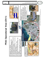
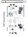
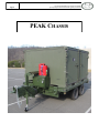
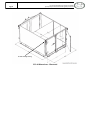
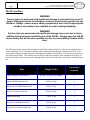
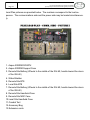
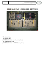
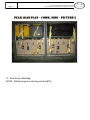
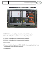
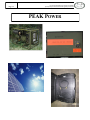
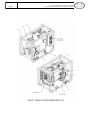
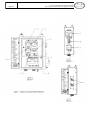
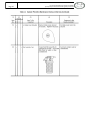
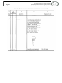
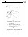
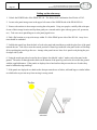
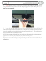
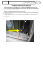
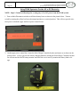
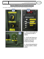
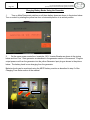
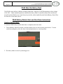
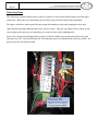
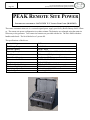
PRE-POSITIONED EXPEDITIONARY ASSISTANCE KIT (PEAK) USER MANUAL—POWER MAIN AND REMOTE SITE MARCH 2012 Pre-positioned Expeditionary Assistance Kit (PEAK) Joint Capability Technical Demonstration (JCTD) User Manual Page 2 TABLE OF CONTENTS SUBJECT PAGE PURPOSE AND OVERVIEW 3 PEAK OPERATIONAL AND SYSTEMS VIEWS - 1 4 PEAK CHASSIS 6 ISU-60 7 ISU-60 LOAD PLAN 9 PEAK POWER 14 MEP-531A (2KW DIESEL) 15 MAIN SITE POWER 36 REMOTE SITE POWER 53 PEAK POINTS OF CONTACT 59 Page 3 Pre-positioned Expeditionary Assistance Kit (PEAK) Joint Capability Technical Demonstration (JCTD) User Manual PURPOSE OF THIS MANUAL The purpose of this manual is to provide the user with an abridged version of the complete versions of the PEAK component user manuals in order to facilitate rapid employment of the PEAK capabilities. It is not intended to replace the manuals provided by the vendors of the PEAK components. Should the user have questions or concerns while operating the components, the user should consult the full version of the respective component manual. If the manual does not provide adequate information, the user should consult technical support of the vendors listed in this manual. WARNINGS AND CAUTIONS Users should become familiar with all components of the PEAK prior to operation, and they should heed all warnings and cautions. Failure to act appropriately may result in death, serious injury, and/or damage to the PEAK equipment. OVERVIEW OF PEAK The Pre-positioned Expeditionary Assistance Kit (PEAK) Joint Capability Technology Demonstration (JCTD) is a joint, interagency and partner nation project over Fiscal Years (FY) 2010-2011. The objective of the PEAK JCTD is to demonstrate and transition an array of capabilities for field distributed essential services including potable water, power, communications and situational awareness. The PEAK kits will provide effective, low-cost and sustainable crisis services that support and build a key capacity in partner nations to promote security and stability in the theater. PEAK will enhance partner nation capabilities to carry out key missions through proactive US military to foreign military engagement and through US civilian organization to foreign government engagement, will improve the partner nations’ ability to provide critical services for targeted purposes during the first days of a natural or man-made crisis through a structured planning process involving public, private, whole of government, and trans-national participants, and will collaboratively enhance regional stability. PEAK OPERATIONAL IMPACT: PEAK will deliver an array of capabilities that can be pre-positioned to help provide sustainable, essential services in the first 72 hours after a disaster event (See PEAK Solution and PEAK OV-1): Potable water from local sources Reliable power from primarily renewable sources Reliable power from primarily renewable sources Local situational awareness & information sharing Page 4 Pre-positioned Expeditionary Assistance Kit (PEAK) Joint Capability Technical Demonstration (JCTD) User Manual Page 5 Pre-positioned Expeditionary Assistance Kit (PEAK) Joint Capability Technical Demonstration (JCTD) User Manual Page 6 Pre-positioned Expeditionary Assistance Kit (PEAK) Joint Capability Technical Demonstration (JCTD) User Manual PEAK CHASSIS Pre-positioned Expeditionary Assistance Kit (PEAK) Joint Capability Technical Demonstration (JCTD) User Manual Page 7 ISU-60 Container (NSN 8145-01-465-3629) The PEAK components are packed inside an ISU-60 container (NSN 8145-01-465-3629) for storage and transportation. ISU stands for internal airlift/helicopter slingable container unit. The ISU-60 is a standard DOD container manufactured by AAR Mobility Systems and is part of the Equipment Deployment and Storage System (EDSS). Per US Army FM 55-80 Army Container Operations, the ISU containers provide weather resistant storage and transport but do not meet ANSI/ISO structural standards. CSC restrictions do not apply to containers specially designed for air transport; however, the container is certified for internal or external helicopter transport and for all AMC transport aircraft. If transported aboard a ship, the ISU should be carried as secondary loads. AAR’s ISU Containers, P/N Series 56000, have been certified by The U.S. Department of Air Force for Air Transportability. The U.S. Army Soldier Systems Center (Natick) has certified the ISU-90 series and ISU-60 series containers for Helicopter Sling Load (HSL). The container is aircraft certified for the C-130, C-5, C-17, KC-10 and CRAF aircraft, and numerous commercial aircraft. Relevant container information may be found at http://www.aarcorp.com/gov/Mobility/Containers/containers_standard.htm. PEAK utilizes a custom designed trailer for movement of the ISU-60, however the ISU-60 may be transported by other military and commercial transportation systems with the capabilities to support the laden ISU-60 and its dimensions. All components required to operate PEAK are located within the ISU-60. The storage configuration of the components within the ISU-60 is optimized to lower the vertical center of gravity and distribute the load laterally across the base of the ISU-60 in order to limit the rollover risk when loaded on the PEAK trailer. The PEAK configuration places the main site power component and diesel generator on one side of the container, and places the communications, water purification, and remote site power systems on the other side of the container. General Characteristics of ISU-60: Length:………………………………108 inches Width:………………………………..88 inches Height: :……………………………...60 inches Max Payload Capacity:………………10,000 lbs Tare Weight:………………………… 1300 lbs PEAK Loaded Weight:……………….4800 lbs All aluminum extruded, mechanically fastened base (eliminates bonded base delamination issues). Four-way forkliftable with oversize forklift tubes; tube size 13 -3/4 inch x 4-1/2 inch. Intermodal – transportable by air, land, sea, or rail. Weather, dust and sand proof structures. Pre-positioned Expeditionary Assistance Kit (PEAK) Joint Capability Technical Demonstration (JCTD) User Manual Page 8 Tie down and Sling load ring ISU-60 Dimensions—Illustrated Pre-positioned Expeditionary Assistance Kit (PEAK) Joint Capability Technical Demonstration (JCTD) User Manual Page 9 ISU-60 Load Plan WARNING Serious injury to personnel and significant damage to personnel may occur if proper lifting procedures including the numbers of personnel required are not followed. Always ensure proper safety equipment is worn and the appropriate numbers of personnel are available to assist loading/unloading. WARNING Serious injury to personnel and significant damage may occur due to items shifting during transport and falling out of the ISU-60. Always open the ISU-60 doors slowly and do not place operators in the area immediately forward of the door. The following section contains the load plan for the PEAK within the ISU-60. Many items within the kit exceed a single man lift. It is imperative that personnel loading and unloading the contents of the ISU-60 observe proper lifting procedures and utilize the appropriate numbers of personnel. The table below provides as list of the heaviest items. This list does not take into account the placement of the equipment in the ISU-60. Items located above the operators head, although lighter than those listed below, may require multiple personnel. Weight (Each) # personnel required Aspen 2000DM Water Purifier 420 lbs (191 kg) (Dry Weight) 6 Aspen 2000DM Support Case 200 lbs (91 kg) 4 Braille OASYS 3kWh Battery Pack 98 lbs (44 kg) 2 MEP-531A Diesel Generator 152 lbs (69 kg) 4 Antenna Mast Bag 77 lbs (35 kg) 2 Main Site Communications Box 62 lbs (28 kg) 2 Remote Site Communications Box 62 lbs (28 kg) 2 Item Page 10 Pre-positioned Expeditionary Assistance Kit (PEAK) Joint Capability Technical Demonstration (JCTD) User Manual Load Plan pictures are provided below. The numbers correspond to the load sequence. The communications side and the power side may be loaded simultaneously. 1. Aspen 2000DM ROWPU 2. Aspen 2000DM Support Case 3. Remote Site Battery (Wheels to the middle of the ISU-60; handle toward the doors of the ISU-60) 4. Water Bladder 5. Remote Site BTS 6. Local Site BTS 7. Remote Site Battery (Wheels to the middle of the ISU-60; handle toward the doors of the ISU-60) 8. Remote Site Handheld Case 9. Remote Site MSC Case 10.Local Site Handheld Case 11.Combat Tent 12.Accessory Bag 13.Extension cords Page 11 Pre-positioned Expeditionary Assistance Kit (PEAK) Joint Capability Technical Demonstration (JCTD) User Manual 14. Antenna Bag 15. Antenna Bag (NOTE: Ratchet strap the antennas in place.) 16. Local Site MSC Case (NOTE: Ratchet strap the MSC Case in place.) Page 12 Pre-positioned Expeditionary Assistance Kit (PEAK) Joint Capability Technical Demonstration (JCTD) User Manual 17. Solar Array Cable Bag (NOTE: Ratchet strap the solar bag and the BTS.) Page 13 Pre-positioned Expeditionary Assistance Kit (PEAK) Joint Capability Technical Demonstration (JCTD) User Manual 1. MEP-531A Generator (May be loaded and unloaded at any time) 2. Main Site Battery Cases (Not to be removed by the Operators) 3. 120 VAC Control Box (Not to be removed by Operators) 4. 220 VAC Control Box (Not to be removed by Operators) 5. Solar Panels 6. Personal Protective Equipment (PPE) (NOTE: Commercial tool kit and Solar Panel stakes are located behind the PPE) 7. Folding Table Page 14 Pre-positioned Expeditionary Assistance Kit (PEAK) Joint Capability Technical Demonstration (JCTD) User Manual PEAK POWER Page 15 Pre-positioned Expeditionary Assistance Kit (PEAK) Joint Capability Technical Demonstration (JCTD) User Manual Page 16 CHAPTER 1 Pre-positioned Expeditionary Assistance Kit (PEAK) Joint Capability Technical Demonstration (JCTD) User Manual SPECIFICATIONS (cont) Page 17 CHAPTER 1 Pre-positioned Expeditionary Assistance Kit (PEAK) Joint Capability Technical Demonstration (JCTD) User Manual SPECIFICATIONS (cont) Page 18 Pre-positioned Expeditionary Assistance Kit (PEAK) Joint Capability Technical Demonstration (JCTD) User Manual Page 19 Pre-positioned Expeditionary Assistance Kit (PEAK) Joint Capability Technical Demonstration (JCTD) User Manual Page 20 Pre-positioned Expeditionary Assistance Kit (PEAK) Joint Capability Technical Demonstration (JCTD) User Manual Page 21 Pre-positioned Expeditionary Assistance Kit (PEAK) Joint Capability Technical Demonstration (JCTD) User Manual Page 22 Pre-positioned Expeditionary Assistance Kit (PEAK) Joint Capability Technical Demonstration (JCTD) User Manual Page 23 Pre-positioned Expeditionary Assistance Kit (PEAK) Joint Capability Technical Demonstration (JCTD) User Manual Page 24 Pre-positioned Expeditionary Assistance Kit (PEAK) Joint Capability Technical Demonstration (JCTD) User Manual Page 25 Pre-positioned Expeditionary Assistance Kit (PEAK) Joint Capability Technical Demonstration (JCTD) User Manual Page 26 Pre-positioned Expeditionary Assistance Kit (PEAK) Joint Capability Technical Demonstration (JCTD) User Manual Page 27 Pre-positioned Expeditionary Assistance Kit (PEAK) Joint Capability Technical Demonstration (JCTD) User Manual Page 28 Pre-positioned Expeditionary Assistance Kit (PEAK) Joint Capability Technical Demonstration (JCTD) User Manual Page 29 Pre-positioned Expeditionary Assistance Kit (PEAK) Joint Capability Technical Demonstration (JCTD) User Manual Page 30 Pre-positioned Expeditionary Assistance Kit (PEAK) Joint Capability Technical Demonstration (JCTD) User Manual Page 31 Pre-positioned Expeditionary Assistance Kit (PEAK) Joint Capability Technical Demonstration (JCTD) User Manual Page 32 Pre-positioned Expeditionary Assistance Kit (PEAK) Joint Capability Technical Demonstration (JCTD) User Manual Page 33 Pre-positioned Expeditionary Assistance Kit (PEAK) Joint Capability Technical Demonstration (JCTD) User Manual Page 34 Pre-positioned Expeditionary Assistance Kit (PEAK) Joint Capability Technical Demonstration (JCTD) User Manual Page 35 Pre-positioned Expeditionary Assistance Kit (PEAK) Joint Capability Technical Demonstration (JCTD) User Manual Page 36 Pre-positioned Expeditionary Assistance Kit (PEAK) Joint Capability Technical Demonstration (JCTD) User Manual PEAK MAIN SITE POWER WARNING The PEAK unit operator will encounter various pinching hazards during setup and breakdown. These hazards are marked with a Pinch Point label and warnings should be heeded to prevent injury. WARNING Solar panels generate DC electricity ANYTIME they are exposed to sunlight. Caution must be taken to never short circuit solar panels or electrical shock may occur. Panels stop producing electricity immediately when they are removed from sunlight. If service on the electrical portion of the array is necessary during daytime hours it is possible to shade the array with a tarp and render it electrically inert. CAUTION Glass solar panels will break if dropped on corners. CAUTION The PEAK unit contains many components that are heavy and require multiple person lift. Use provided lifting handles and test lift components prior to actual lifting to make sure enough personnel are available to safely lift components. Page 37 Pre-positioned Expeditionary Assistance Kit (PEAK) Joint Capability Technical Demonstration (JCTD) User Manual Setting up the solar array 1. Unlock the POWER side of the PEAK ISU-60. The factory lock combination for all locks is 2345. 2. Locate solar panel storage area in the upper left corner of the POWER side of the PEAK ISU-60 3. Remove the ratchet tie down straps securing the solar panels. Using two people, carefully slide solar panels out of their storage location and lay them gently on a smooth surface glass side up (grass, soil, pavement, etc.). Take care not to pinch fingers or solar panel pigtail wires. 4. Find a flat location to set up solar arrays within 50 ‘of the PEAK power side of the ISU-60. Array Locations should be unshaded. 5. Unfold solar panel legs from the back of each solar panel and stand them up with the glass face of the panel towards the sun. Take care to note the stowed position of frame legs inside the solar panel as this will be helpful in repacking the panel legs after use. Arrange solar panels in two lines of six panels each placing the panels edges side by side. 6. Using the metal tent stakes located in the red plastic box labeled “stakes” anchor each solar panel to the ground. The stakes fit through anchor holes on the bottom of the panel leg and can be driven into the ground with the supplied hammer. If the panels are deployed on a hard surface that prevents the use of stakes they must be ballasted using sand bags. 7. If the panels are deployed on a hard surface that prevents the use of stakes, add sand bags or similar ballast over ballast bar to prevent array from moving is strong winds. Page 38 Pre-positioned Expeditionary Assistance Kit (PEAK) Joint Capability Technical Demonstration (JCTD) User Manual 8. ONLY attach the positive (+) and negative (-) electrical cables on the back side of the first two solar panels in the line of 6 panels to each other. The panel pigtail wire lengths will only allow you to make the correct connection. 9. Locate solar array cable and lay it out between solar array and control boxes. Array end of the cables is the end with a longer length of exposed black wires. Taking the array end of the cable attach two of the wires to the remaining two loose pigtails from the solar panels connected in step 10. This results in an electrical circuit that has only two solar panels in series. NOTE: It does not matter which of the black wires on the array cables attach to the two loose solar panel pigtail wires. As long as the plugs fit physically, they will be electrically correct. Repeat steps 8 and 9 for the remaining ten solar panels making sure that each electrical circuit has only two solar panels in it. Page 39 Pre-positioned Expeditionary Assistance Kit (PEAK) Joint Capability Technical Demonstration (JCTD) User Manual 10. Attach the control box end of the array cables to Solar Input receptacles located on the face of the silver Solar Combiner box. This box is located between the 120 VAC and 220 VAC control boxes. NOTE: It does not matter which of the black wires on the array cables attach to the control box array receptacles. As long as the plugs fit physically, they will be electrically correct. 11. Solar panels should be broken down and stored in the reverse order of setup. Solar panels MUST be stowed in the solar panel storage area GLASS DOWN. This is to prevent the panel legs from dropping and breaking the glass of the panel below. 12. When all panels are stowed in the panel storage area the ratchet straps should be snugged down to prevent movement in transport. Pre-positioned Expeditionary Assistance Kit (PEAK) Joint Capability Technical Demonstration (JCTD) User Manual Page 40 Grounding the POWER Side of the PEAK ISU-60 1. Unlock the POWER side of the PEAK ISU-60. The factory lock combination for all locks is 2345. 2. Locate one of the four provided grounding kits (one for generator, one for the POWER side of the ISU60, and one for each communications antenna) 3. Assemble the grounding rod by screwing the sections together. 4. Using the provided ground wire, attach one end of the wire to the control box grounding point and the other end to the ground rod. 5. Using the supplied slide hammer, drive grounding rod into the earth thereby completing the electrical grounding circuit. Grounding Point Page 41 Pre-positioned Expeditionary Assistance Kit (PEAK) Joint Capability Technical Demonstration (JCTD) User Manual Using PEAK System to Provide AC or DC Electricity NOTE: Steps 1-3 must be followed prior to using any AC or DC power from the PEAK system 1. Turn on Main Disconnect switches on all three battery boxes as shown in the picture below. Turn on switch by rotating the yellow bar from a horizontal position to a vertical position. This will now provide electrical power to both the upper and lower power control boxes. 2. On the upper power control box, locate the Solar Charge Controller breaker and turn it on as shown in the picture below. (even if you are not actively charging batteries, turning the Solar Charge Controller breaker on will activate the MATE battery monitor and allow the user to actively monitor the battery bank voltage). Page 42 Pre-positioned Expeditionary Assistance Kit (PEAK) Joint Capability Technical Demonstration (JCTD) User Manual 3. On the 220VAC power control box, locate the MATE battery and charging monitor screen and verify battery bank voltage. Press Status/CC/Meter to get to the meter screen and then use the Down/Up buttons to scroll through the various display parameters. See picture below. Battery voltage will be maintained between 42 and 53 VDC. Any battery voltage over 50 VDC represents a fully charged battery bank. Page 43 Pre-positioned Expeditionary Assistance Kit (PEAK) Joint Capability Technical Demonstration (JCTD) User Manual 3. On the 120VAC power control box, locate the battery and state of charge monitor screen and verify battery bank voltage. Using the arrow buttons the meter will scroll through the various display parameters. See picture below. Battery voltage will be maintained between 42 and 53 VDC. Any battery voltage over 50 VDC represents a fully charged battery bank. Page 44 Pre-positioned Expeditionary Assistance Kit (PEAK) Joint Capability Technical Demonstration (JCTD) User Manual Preparing PEAK System to Provide DC Electricity Following the sequence shown in the picture below, switch on and operate DC loads. Pre-positioned Expeditionary Assistance Kit (PEAK) Joint Capability Technical Demonstration (JCTD) User Manual Page 45 Using PEAK System to Provide 120VAC Electricity Locate the power control box. Following the sequence shown in the steps below. 1. Turn on the 120 VAC Inverter Breaker 2. On the 120 VAC Load Center turn on the AC Main 30A breaker 3. On the 120VAC Load Center turn on the Outlets breaker 4. Open the desired 120 VAC GFI Outlet cover and plug in desired load Page 46 Pre-positioned Expeditionary Assistance Kit (PEAK) Joint Capability Technical Demonstration (JCTD) User Manual Using PEAK System to Provide 220VAC 1Ø Electricity Locate the power control box. Following the sequence shown in the picture below, switch on and operate 220VAC single phase loads. Page 47 Pre-positioned Expeditionary Assistance Kit (PEAK) Joint Capability Technical Demonstration (JCTD) User Manual Charging Batteries with Solar 1. Set up solar array as described in Setting Up Solar Array section of the manual. 2. Electrically connect solar array to control box as described in Setting Up Solar Array section of the manual. 3. Turn on Main Disconnect switches on all three battery boxes as shown in the picture below. Turn on switch by rotating the yellow bar from a horizontal position to a vertical position. 4. On the upper power control box, locate the Solar Charge Controller breaker and turn it on as shown in the picture below. Page 48 Pre-positioned Expeditionary Assistance Kit (PEAK) Joint Capability Technical Demonstration (JCTD) User Manual 5. On the lower power control box, locate the MATE battery and charging monitor screen and verify that current is being produced by the solar panels and is charging the batteries. Press Status/ CC/Meter to get to the meter screen and then use the Down/Up buttons to scroll through the various display parameters. See picture below. 6. The system is now charging from the sun and will automatically keep the batteries charged to the appropriate levels through day and night cycles. No further operator input is necessary and solar charging will continue indefinitely whenever there is sunlight available. Battery voltage will be maintained between 42 and 53 VDC. Any battery voltage over 50 VDC represents a fully charged battery bank. Pre-positioned Expeditionary Assistance Kit (PEAK) Joint Capability Technical Demonstration (JCTD) User Manual Page 49 Charging Battery Banks Using the Generator 1. Turn on Main Disconnect switches on all three battery boxes as shown in the picture below. Turn on switch by rotating the yellow bar from a horizontal position to a vertical position. 2. On the upper power control box, locate the 120 V Inverter Breaker as shown in the picture below and turn it on. Start generator as described in the generator section of the manual. Plug the output power cord from the generator into the yellow Generator Input plug as shown in the picture below. The battery bank is now charging from the generator. Batteries levels can be monitored using the MATE battery monitor as described in step 5 of the Charging From Solar section of the manual. Generator Input Inverter Breaker Pre-positioned Expeditionary Assistance Kit (PEAK) Joint Capability Technical Demonstration (JCTD) User Manual Page 50 PEAK Main Site Battery Bank The PEAK system utilizes a lithium ion battery bank with a capacity of 18 kWh operating at a buss voltage of 48 VDC. Under standard operation conditions the battery bank is controlled (connected to and disconnected from the PEAK power control boxes) by the 60A yellow handled breaker labeled Battery Shut Off on the front face of the battery boxes. PEAK Battery Module Start and Shut-Down Instructions Starting Module Bank To start the PEAK battery module bank from a completely shut down state: 1. Turn on Battery Shut Off switches on all three battery boxes as shown in the picture below. Turn on switch by rotating the yellow bar from a horizontal position to a vertical position. 2. The battery banks are now be producing power. Page 51 Pre-positioned Expeditionary Assistance Kit (PEAK) Joint Capability Technical Demonstration (JCTD) User Manual Shutting Down a Module Bank For storage or transportation it is recommended to completely shut down the PEAK battery modules. To turn off the PEAK batteries: 1. Turn off Battery Shut Off switches on all three battery boxes as shown in the picture below. Turn off switch by rotating the yellow bar from a vertical position to a horizontal position. 2. The batteries are now turned off and are prepared for storage or transport Page 52 Pre-positioned Expeditionary Assistance Kit (PEAK) Joint Capability Technical Demonstration (JCTD) User Manual Solar Array Fuses The solar array is protected from short circuits by a bank of six fuses located in the inside rear of the upper control box. Blown fuses are indicated by the red LED on top of the fuse block being illuminated. The upper control box can be opened by unscrewing the thumbscrew latch and swinging the door open. Under normal operating conditions these fuses will never blow. They are only likely to blow if there is transient voltage in the solar array to control box wire such as from a nearby lightning strike. Fuses can be changed by pulling the dark grey door of the fuse holder open and removing blown fuse and inserting a new one. Fuse specifications are 10A and ample spares are included in the accessory toolkit. See picture below for fuse block location. Pre-positioned Expeditionary Assistance Kit (PEAK) Joint Capability Technical Demonstration (JCTD) User Manual Page 53 PEAK REMOTE SITE POWER INFORMATON PROVIDED BY OASYS 3KW 12 V SYSTEM USER GUIDE (MAR 2012) The remote communications site is a custom designed power supply provided by Braille Battery OASYS Energy. The remote site power configuration is weather resistant. The batteries are recharged using the main site solar array or the generator. Two remote site batteries are provided with the kit. The kit is fitted with three handles and wheels. The kit is labeled as a 3-person lift. The specifications of the kit are: Nominal Voltage 12.8V Full Charge Range 13.2-13.6 V Nominal Capacity 240 Ah, 3kWh Operating Temperature –20°C to +50°C (below 0C limited functionality) Max Temperature 65C constant (75 C pulse temp) Short Circuit Protection Yes, System Off (Recovery – Switch On) Dimensions H / W / D 31.30” x 20.40” x 15.50” Weight Estimated Usable Wattage Maximum Watt Output Low Voltage Protection High Voltage Protection 98 lbs (44.45 kg) 3000 wh (230+ AH, with 12+V average) 550 Watts Undervoltage: 11.2-12.0V cut off Overvoltage: 15.0V Page 54 Pre-positioned Expeditionary Assistance Kit (PEAK) Joint Capability Technical Demonstration (JCTD) User Manual The Braille OASYS 3kWh Battery Module has one simple ON and OFF push button. Prior to use, ensure battery is charged by viewing “percentage charged” on the battery monitor prior to powering ON battery. Battery can be charged at PEAK home site by plugging into any 110 VAC outlet. POWER ON Battery: 1. Open battery case to remove power cable 2. Connect appropriate end to base station power outlet located on front 3. Connect opposite end to Braille OASYS 3kWh Battery 4. Depress push button for once until blue light ring illuminates around button showing power is flowing from battery POWER OFF Battery: 1. Depress push button for several seconds until blue light ring is no longer lit 2. Disconnect power cable from base station and battery 3. Store cable inside battery box Charging Battery Using AC Charger: 1. Connect supplied AC charging cord to the matching receptacle on the Braille OASYS 3kWh battery case. This cable is identified by the standard 120 VAC AC three prong plug on one end. 2. Plug the AC Battery Charger into an AC outlet. NOTE: The battery charger will turn off automatically once the battery is fully charged Page 55 Pre-positioned Expeditionary Assistance Kit (PEAK) Joint Capability Technical Demonstration (JCTD) User Manual BATTERY OPERATION The Braille Oasys 3kw is a very simple to operate device. With a single master power switch and a easy to navigate battery monitor, this allows for personnel to operate the system effectively, even without advanced training. The redundant design, on-board charging and integrated safety systems allow for portable energy storage in a wide variety of operational conditions. POWERING SYSTEM ON / OFF To Power the System between an “active-on” or “inactive-off” mode, depress the single circular power switch: ON: Press Momentarily - Once ON the blue illuminated ring will be ON. If the blue ring is illuminated the master internal switch makes internal contact and will provide 12volt power supply to the output connector. OFF: Press and hold for 3-4 seconds. If the blue ring is not illuminated the output connecter will not provide power. SYSTEM CHARGING Utilizing the onboard charger is activated by plugging the external input connector to 110/220 volt power AC power. The onboard charger will automatically switch for the input voltage and initiate charging if the battery voltage or capacity is below 95-98% state of charge. Once charging is initiated the charge current will continue until the battery reaches 98-100% state of charge or when the power supply cable is disconnected. The system will automatically connect and turn on during charging. If the system was off, after disconnecting charger, system will remain off. SYSTEM STORAGE Recommended Storage Voltage: >13.0 Volts @ 78F Page 56 Pre-positioned Expeditionary Assistance Kit (PEAK) Joint Capability Technical Demonstration (JCTD) User Manual is turned off. This will allow for a longer storage term and then the ability to have higher capacity when returned to service. BATTERY GAUGE The Braille OASYS battery monitor allows for simple operation by toggling the left or right arrows to scroll through the following display modes: • Battery Voltage • Battery State of Charge • Battery Current Draw • Battery Total Amp Hours Consumed • Battery Run Time Remaining Battery Temperature NOTE: The OASYS Monitor has been designed to automotically reset (synchronize) after each full charge which occurs. This will reset the following items: • Battery State of Charge Battery Total Amp Hours Consumed In the event you wish to meter just the amperage consumed during a test or an event, you can synchronize the meter by depressing both buttons. Page 57 Pre-positioned Expeditionary Assistance Kit (PEAK) Joint Capability Technical Demonstration (JCTD) User Manual Page 58 Pre-positioned Expeditionary Assistance Kit (PEAK) Joint Capability Technical Demonstration (JCTD) User Manual OASYS 3kWh Remote Site Battery Module Pre-positioned Expeditionary Assistance Kit (PEAK) Joint Capability Technical Demonstration (JCTD) User Manual Page 59 POINTS OF CONTACT PEAK MAIN SITE POWER, REMOTE SITE POWER, CHASSIS AND TRAILER WorldWater & Solar Technologies, INC 330 Carter Road Princeton, NJ 08540 USA 609-356-0372 [email protected]