1
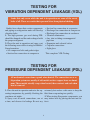
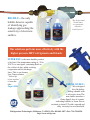
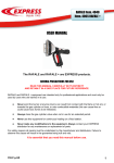
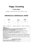
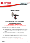
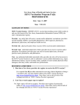
WE’RE TAKING
LEAK DETECTION
TO A
HIGHER LEVEL
Approved
FOOD GRADE
Non Toxic - Biodegradable - Oxygen Safe
Copyright 2008
Printed in USA
REFRIGERATION TECHNOLOGIES
Guide to Basic and Advanced Refrigerant Gas
LEAK DETECTION
By reading, understanding and practicing the techniques outlined
in this manual, the Refrigeration Service Mechanic will
finally master the art of Leak Detection.
(The most under-taught skill in our trade)
Lesson 1
PG
EVERYTHING LEAKS. . . . . . . . . . . . . . . . . . . . . . . . . . . . . . . . . 1
Lesson 2 THE IMPORTANCE OF SENSITIVITY. . . . . . . . . . . . . . . . . . . . 2
Lesson 3 THE SIX CLASSES OF LEAKS. . . . . . . . . . . . . . . . . . . . . . . . . . 2
Lesson 4
REQUIRED TOOLS. . . . . . . . . . . . . . . . . . . . . . . . . . . . . . . . . . . 3
Lesson 5
BASIC LEAK DETECTION
Testing for the Standing Leak. . . . . . . . . . . . . . . . . . . . . . . . . . 4
Spotting Refrigeration Oil Residue. . . . . . . . . . . . . . . . . . . . . . 4
The Reliability of Oil Spotting. . . . . . . . . . . . . . . . . . . . . . . . . 4
Testing for Evaporator Section Leaks. . . . . . . . . . . . . . . . . . . . 5
Testing for Condensing Section Leaks. . . . . . . . . . . . . . . . . . . 5
Suction/Liquid Line Leak Test. . . . . . . . . . . . . . . . . . . . . . . . . 6
Lesson 6 ADVANCED LEAK DETECTION
Testing for Pressure Dependent Leakage. . . . . . . . . . . . . . . . . 7
Testing for Vibration Dependent Leakage. . . . . . . . . . . . . . . . 8
Testing for Temperature Dependent Leakage. . . . . . . . . . . . . . 8
Testing for Combination Dependent Leakage. . . . . . . . . . . . . . 9
Testing for Cumulative Micro - Leaks. . . . . . . . . . . . . . . . . . . 9
© 2008 Refrigeration Technologies
EVERYTHING LEAKS
All sealed systems leak. The leak
could be at 1-lb. per second or as
slow as 1-oz. every million years.
Every pressure system has leaks
because “flaws” exist at every joint
fitting, seam or weld. These “flaws”
may be too small to detect even with
the best of leak detection instruments. But given time, vibration,
temperature and environmental
stress, these “flaws” become larger,
detectable leaks.
A LEAK IS NOT...Some arbitrary
reading on a meter. Gas escapes at
different times and at different rates.
In fact, some leaks cannot be detected at the time of the test. Leaks
may plug, then re-open under peculiar conditions.
A LEAK IS...A physical path or
hole, usually of irregular dimensions. The leak may be the tail end
of a weld fracture, a speck of dirt on
a gasket or a microgroove between
fittings.
An electron micrograph of a “clean” silver soldered Further magnification shows actual metal separajoint. Note the crack lines and other impurities of
tion. The leak rate was measured to be 0.00003 oz/yr,
the melted metal.
R-22 gas. After 1 year of system operation, the cracks
opened to 0.00016 oz/yr.
It is incorrect to state that a unit has no “leaks.” All equipment has leakage to
some degree. A sealed system which has operated for 20 years without ever needing a charge is called a “tight system.” The equipment still has leaks, but not
enough leakage to read on a guage or affect cooling performance. No pressurized
machine is perfect.
1
THE IMPORTANCE OF SENSITIVITY
Sensitivity is the measure of performance in leak finding devices. High sensitivity means “fine” leak
detection. Low sensitivity is considered “gross” detection.
Refrigeration Technologies has developed a
fluid coating of remarkable leak reactant sensitivity.
Progressive compositions trademarked as
“BIG BLU” are now capable of magnifying
micro-gas leakage as small as 0.65 oz./yr. into
visible foam “cocoons.”
Our research work has been verified and
published in several distinguished scientific
journals.1
Reference: American Society for Non-Destructive Testing “The Study
of Leak Detection Fluids.” Materials Evaluation. Vol 49 No. 8, Pages
1035-1037, August 1991.
1
The advent of fine electronic sensing devices proves
that microscopic leaks do in fact exist, and leaks larger than 0.5 oz/yr. can be detrimental to the operation
of any refrigeration system.
Bubble testing is gross because only large leaks
(above 4.2 oz./yr.) and leaks of proper position can
be detected.
This can be demonstrated when a fitting is electronically sensed as leaking, but secondary application of
a bubble solution to confirm the site yields no bubble
or foam formation. The question immediately
The super sensitivity of the Big
Blu fluid is demonstrated by
micro-foam “cocooning” of
R-11 vapor off a reference leak.
confronting the technician is:
1. Did the electronic give a false reading? OR
2. Does the bubble solution lack the sensitivity to
show the leak?
Refrigeration Technologies has conducted extensive
studies investigating all the faults of bubble leak testing.
The failure of bubble solutions lies in their composition. Most are based on shampoo, bubble bath or dish
washing soap, and usually contain artificial thickeners, fluorescent dyes, or glycerine that dramatically
kill leak sensitivity.
THE SIX CLASSES OF LEAKS
Refrigeration Technologies has determined six (6) types of leaks you will
at sometime during your servicing experience come to know.
Class 1. Standing Leaks (SL) are leaks that can be conducted if no leaks are discovered by the SL test.
detected while the unit is at rest (off) and fully equal- Class 3. Temperature Dependent Leaks (TDL) are
ized. This shall include freezer evaporative coils leaks associated with the heat of expansion. TDL usuwarmed up by defrost. SL leaks, fortunately, are the ally occurs from high ambient air, condenser blockmost common of all.
age or during defrost.
Class 2. Pressure Dependent Leaks (PDL) are leaks Class 4. Vibration Dependent Leaks (VDL) occur
that can only be detected as the pressure is built. Ni- only during unit operation. The mechanical strain of
trogen is used to pressurize low sides to 150 psi and motion, rotation, refrigerant flow, or valve actuation
high sides to 450 psi. Never use CO2 or Oxygen. He- are all associated with VDL.
lium or dry air is acceptable. PDL testing should be
2
Class 5. Combination Dependent
Leaks (CDL) are flaws that require
two or more conditions in order to
induce leakage. For example, temperature, vibration and pressure
cause the discharge manifold on a
semi-hermetic compressor to expand and seep gas.
Class 6. Cumulative Micro-Leaks
(CML) are all the individual leaks
that are too small to detect with
standard tools. The total loss over
many years of operation slightly
reduces the initial gas charge. In
practice, a system having many
fittings, welds, seams or gasket
flanges; the greater the amount of
CML.
OEM’s and field installers should always conduct a PDL test before
charging a system with refrigerant. Nitrogen pressurization to 450 psi
reveals a cracked receiver seam indicated by white micro foam.
REQUIRED TOOLS
We are all intuitively equipped with basic leak detection tools. With our ears we can hear large leaks. With
our nose, we can smell certain gases. With our fingers,
we can feel for oil residue which surrounds many
leaks sites. But the best leak confirmation comes by
sight. The verification of a leak by watching bubbles
or foam actively brew at the point of leakage.
This manual describes a systematic method of
search using common leak detection tools.
1. An electronic halogen instrument having a
sensitivity of at least 0.50 oz./yr.
2. Our BIG BLU Bubble/Foam Promoter.
3. An inspection mirror.
4. A light source.
The electronic sensor shall be used as a screening
tool to “sniff” which component is emitting gas.
BIG BLU will be used to spray coat ALL surfaces of the target component.
We shall then observe for any bubble/foam
emissions, using when necessary, an inspection
mirror to view blind sides and a light source for
illuminating dark areas.
3
BASIC LEAK DETECTION
Field Testing for the Standing Leak (SL)
Successful leak detection is solely dependent
on the careful observations made by the testing technician.
SPOTTING REFRIGERATION OIL RESIDUE
Fortunately, all refrigeration systems circulate compressor oil internally. Oil will blow-off with refrigerant gas and mark the general areas of leakage.
Oil spots appear wet and have a fine coating of
dust. Determine that the wetness is oil and not condensate by rubbing the area with your fingers to feel
for oil slickness.
The faint dark area on this vibration eliminator is evidence of oil-refrigerant seepage.
1. With the unit fully pressurized to equalization, spray coat all oily areas with “BIG BLU”.
2. Observe for bubble/foam emission.
3. Continue to observe the area for at least 10 minutes to allow time for micro-leaks to build a cocoon of foam.
RELIABILITY OF OIL SPOTTING
Oil spotting is the technician’s first quick-check,
but not reliable for the following reasons:
1. Oil is always present at schraeder valves and
access ports due to the discharging of refrigerant hose gauges. Often these ports are falsely
blamed as the main point of leakage.
2. Oil blotches can originate from motors, pumps,
or other sources.
3. Oil residue may be the result of a previous
leak.
4. Oil is not always present at every leak site. It
may take many months, even years of unit operation to cause enough oil blow-off to accumulate
on the outer side.
5. Oil may not be present with micro leaks.
6. Oil may not reach certain leak positions.
7. Oil will not be present on new start ups.
Tightly cap off
all valve ports
and continue to
search for the
real leak source.
4
TESTING FOR EVAPORATOR SECTION LEAKS
Many leaks that go undetected are in the Evaporator
Coil. This is because evaporator sections are cabinet
contained, buttoned-up or framed into areas that do
not allow easy access. In order to avoid time consuming labor to strip off covers, ducting, blower cages, or
the unloading of product, an easy electronic screen-
ing method is outlined:
1. Turn off all system power including evaporator fan
motors.
2. Pressurize system to equalization including defrosting of freezer coils.
3. Warm-up and calibrate an electronic sniffer to its
highest sensitivity.
4. Locate the evaporator drain outlet or downstream trap.
5. Position the detector probe at the drain opening.
(Be careful that the probe does not come in contact
with any water).
6. Sniff a minimum of 10 minutes or until a leak is
sensed. Recalibrate the device and test again. Two
consecutive POSITIVE tests confirms an evaporator leak. Two consecutive NEGATIVE tests rules
out a detectable evaporator section leak.
Refrigerant gas is heavier than air, and gravity
will cause the gas to flow to the lowest point. If the
evaporator section tests positive, we must expose
the coil and spray coat ALL surfaces with BIG
Sniff the outlet of the condensate drain pipe to confirm BLU.
or rule out an evaporator leak.
TESTING FOR CONDENSING SECTION LEAKS
Just as the electronic sensor was used to screen for utes as above.
evaporator leaks, we have devised a quick method for 5. If the results are positive, uncover the equipment
determining condensing section leakage.
and begin spray coating with BIG BLU. If the results
1. Calibrate an electronic sniffer to its highest sensi- are negative, continue to the Suction/Liquid line leak
tivity and place the probe at the base of the unit (usu- test.
ally under the compressor). Unit should be
fully pressurized to equalization.
2. Cover the condensing unit with a cloth
tarp or bed sheet to serve as a barrier against
any outside air movement and also trap refrigerant gas. Do not use a plastic material.
3. Monitor for leakage for ten (10) minutes
or until a leak is sensed. Re-calibrate and
test again. Two consecutive positive tests
confirm condensing section leakage: Two
consecutive negative tests rule out a detectable leak.
4. Use the electronic sniffer to test for leaking bellows on pressure controls. Remove
the control box cover and place the probe
Cover the condensing unit (or section on a package unit)
within the housing. Cover the control tightly
to pick up any refrigerant drift. The cloth barrier
with a cloth barrier and monitor for ten minprevents air dilution.
5
Basic Leak Detection Continued
SUCTION/LIQUID LINE LEAK TEST
The longer the tubing runs between the evaporator and condensing unit,
the greater the odds for defects. Count on all possibilities whether it be
a typical sight glass drier connection leak to a poor solder joint hidden
under pipe insulation.
1. The suction line can be screened by calibrating an electronic to it’s highest sensitivity.
2. Tuck the probe underneath the pipe insu-
lation. Monitor at ten minute intervals while
the system is at rest and fully pressurized to
equalization. It may be necessary to insert the
probe at several downstream points.
An insulated pipe being scanned for leakage. It is important that the insulating material is not glued
to the metal pipe and does not have any open gaps or tears.
3. If a leak is sensed, strip off insulation and 4. The liquid line almost always has oil resiapply BIG BLU to all pipe surfaces. If no leak due as the result of leakage. Coat all suspected
was positively screened, test liquid line.
liquid line connections with BIG BLU allowing sufficient time (10-15 minutes) for microfoam expansion.
6
ADVANCED LEAK DETECTION
Leakage that avoids detection by the basic
For advanced leak detection the electronic
field test (SL) must be determined by Nitrogen halogen detector cannot be used. We shall rely
pressurization (PDL), run-vibration (VDL), on the super sensitive microfoamers unique to
or by adding heat (TDL).
the BIG BLU fluid coating.
TESTING FOR
PRESSURE DEPENDENT LEAKAGE (PDL)
On newly connected field installations, always proceed to the PDL Test. The
old habit of pressure checking with Refrigerant Gas, besides being taboo, is
more expensive, more time consuming and less reliable.
On existing systems, the technician must properly remove and store any refrigerant charge.
1. Pressurize the low side to 150 psi and the
high side to 450 psi using dry Nitrogen, Helium or dry air. If the high and low sides cannot
be split by way of isolation valves, pressurize
the entire system to about 350 psi.
2. Always conduct proper bubble testing by
thoroughly saturating all surfaces with BIG
BLU. Allow up to 15 minutes reaction time
for the microfoamers to expand into visible
white “cocoon” structures. Use an inspection
mirror to view undersides and a light source
for dark areas.
3. Starting at the compressor, coat all suspected surfaces. Continue to coat all suction line
connections back to the evaporator section.
4. Spray coat all fittings starting with the discharge line at the compressor to the condenser coil. Spray coat all the soldered condenser
coil U-joints.
5. From the condenser, continue to spray coat
all liquid line connections including the receiver (valves, seams, pressure taps and any
mounting hardware). Continue the liquid line
search back to the evaporator section.
6. Any control line taps to the sealed system
must be spray coated the entire length of their
run all the way back to the bellow device.
7. Expose the evaporator section and coat all
connections, valves and U-joints.
Our first sequence of search started with the
compressor and suction line due to their large
surface areas. The next sequence begins with
the discharge line, across the condenser to the
liquid line connection at the evaporator section. The evaporator section is the last and
least desirable component to pressure test in
the field.
This completes the PDL Test.
7
TESTING FOR
VIBRATION DEPENDENT LEAKAGE (VDL)
Leaks that only occur while the unit is in operation are some of the rarest
leaks of all. These are cracks that open and close from physical shaking.
Studies have shown that certain components
and piping on refrigeration units will develop
vibration leaks.
1. The high pressure gas used during PDL
should be dumped and the unit recharged with
the proper refrigerant.
2. Place the unit in operation and spray coat
the following areas while viewing for Bubble/
Foam formation:
• All compressor bolts and gasket edges
• Suction line connection at compressor
• Suction line connection at evaporator
• Discharge line connection at compressor
• Discharge line connection at condenser
• Vibration eliminators
• Any joint or fitting on unsupported
pipe runs
• Expansion and solenoid valves
• Cap tube connections
• Sight glass
This completes VDL Testing.
TESTING FOR
PRESSURE DEPENDENT LEAKAGE (PDL)
All mechanical connections expand when heated. The connections on a refrigeration system are usually of soft metals such as copper, brass or aluminum. These metals actually warp when heated, then contract and seal when
heat is removed.
1. Place the unit in operation and raise the operating temperature by partially blocking the
condenser air intake.
2. Spray coat all metal connections, one at
a time, and observe for leakage. Re-wet any
extremely hot surface with water to keep the
fluid from evaporating too quickly.
3. When testing Evaporator components, you
may induce heat by placing the unit into defrost.
8
TESTING FOR
COMBINATION DEPENDENT LEAKAGE (CDL)
1. A valve or fitting is subjected to high pressure.
2. Spray coat the valve or fitting.
3. Tap the component repeatedly with a rubber mallet
to induce vibration. If no leakage...
4. Gently add heat to the component. If no leakage,
continue on to another component.
This completes a labor intensive CDL test.
CDL testing is overlapped by the PDL, VDL and TDL
procedures. CDL can only be determined by merging
at least two, possibly all three procedures into one.
The CDL test requires the highest order of skills and
observation techniques. Each suspected component
must be isolated and tested in the following manner:
TESTING FOR
CUMULATIVE MICRO-LEAKS (CML)
CML are measured using a Helium Mass Spectrom- CML is considered an acceptable amount of leakage
eter. Such super fine leak testing is beyond the normal in our industry at this point in time.
operations of the Refrigeration Service Mechanic.
BIG BLU is an exclusive composition of micro-foaming compounds,
wet adhesives and coagulants. The presence of dirt, oil or water
does not affect bubble production.
Foam Cocoons: BIG BLU is the only gas leak detector that
can reveal gas leakage down to 0.5 oz/yr.
THE IMPORTANCE OF SENSITIVITY...
BIG BLU is the only fluid that can reveal gas leaks
BIG BLU is an exclusive composition of esoteric
far below 4.2 oz./yr.
micro - foamers coupled into a base of coagulants and
wet adhesives.
9
BIG BLU....the only
bubble detector capable
of identifying gas
leakage approaching the
sensitivity of electronic
sniffers.
“The Professional
Technician is
very particular
about his
Leak Detector”
Our solutions perform more effectively with the
higher pressure HFC refrigerants and blends.
SUPER BLU is the most durable product
of its kind. Our temperature rating of -30 to
200°F is a true figure, remaining fluid on
the coldest of days while resisting
evaporation on hot discharge
lines. This is our former
Low Temp solution
“kicked up
a few notches”
to earn the
title...
Super Blu
Approved
Brush On Blu:
We redesigned
the old dauber,
adding a handle with
a telescopic stem. The
new dauber transfers a
flatter liquid, free of counterindicating bubbles or foam. Freeze
resistant to about 0°F with a smooth and
silky viscosity for excellent hold.
Refrigeration Technologies, Fullerton, CA 92831 • Ph: 800-869-1407 • Fax: 714-526-4598
http://www.refrig.com