1
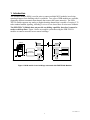
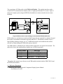
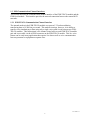
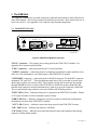
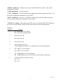
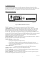
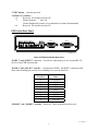
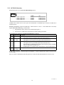
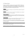
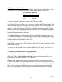
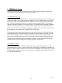
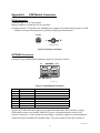
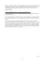
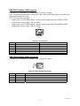
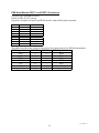
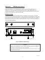
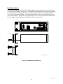
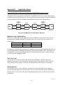
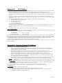
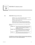
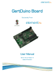
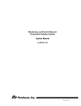
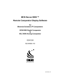
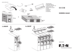
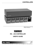
Monitoring and Control Network
Extender Module (EXB)
User Documentation
S2-60596-115
CTI Products, Inc.
1211 West Sharon Road
Cincinnati, Ohio 45240
(513) 595-5900
(513) 595-5983 Fax
Information contained in this document is subject to change without notice and does not represent a commitment on the part of CTI
Products, Inc.
No part of this manual may be reproduced or transmitted in any form or by any means, electronic or mechanical, including
photocopying and recording, for any purpose without the written permission of CTI Products, Inc.
Copyright (c) 1996-2002 CTI Products, Inc. All rights reserved
EXB Module and WON are trademarks of CTI Products, Inc.
68-11089-115
Standard Limited Hardware Warranty
LIMITED WARRANTY. Equipment manufactured by CTI Products, Inc. is warranted to be free from defects in material and
workmanship for a period of ONE (1) YEAR from date of shipment to original purchaser. Under this warranty, our obligation is
limited to repairing or replacing any equipment proved to be defective by our inspection within one year of sale to the original
purchaser. This warranty shall not apply to equipment which has been repaired outside our plant in any way, so as to, in the
judgment of CTI Products, Inc. affect its stability or reliability, nor which has been operated in a manner exceeding its specifications,
nor which has been altered, defaced, or damaged by lightning.
CUSTOMER REMEDIES. In the event of a defect, malfunction, or failure to conform to specifications established by the seller
during the period shown, the customer shall call CTI Products, Inc. to obtain a Return Authorization Number and return the product
or module, shipping and insurance prepaid. CTI Products, Inc., will then at its option, either repair or replace the product or module
and return it, shipping prepaid, or refund the purchase price thereof. On-site labor at the purchaser's location is not included in this
warranty.
EQUIPMENT NOT MANUFACTURED BY CTI Products, Inc. Equipment not manufactured by CTI Products, Inc. is excluded
from this warranty, but is subject to the warranty provided by its manufacturer, a copy of which will be supplied to you upon specific
written request.
NO OTHER WARRANTIES. The foregoing constitutes the sole and exclusive remedy of the buyer and exclusive liability of CTI
Products, Inc., AND IS IN LIEU OF ANY AND ALL OTHER WARRANTIES EXPRESSED OR IMPLIED OR STATUTORY AS
TO MERCHANTABILITY, FITNESS FOR PURPOSE SOLD, DESCRIPTION, QUALITY, PRODUCTIVENESS OR ANY OTHER
MATTER.
NO LIABILITY FOR CONSEQUENTIAL DAMAGES. WITHOUT LIMITING THE FOREGOING, IN NO EVENT SHALL
CTI PRODUCTS, INC. OR ITS SUPPLIERS BE LIABLE FOR ANY DAMAGES WHATSOEVER (INCLUDING, WITHOUT
LIMITATION, SPECIAL, INCIDENTAL OR CONSEQUENTIAL DAMAGES OR FOR LOSS OF BUSINESS PROFITS,
BUSINESS INTERRUPTION, LOSS OF BUSINESS INFORMATION, OR OTHER PECUNIARY LOSS) ARISING OUT OF THE
USE OF OR INABILITY TO USE CTI PRODUCTS, INC. EQUIPMENT BY PURCHASER OR OTHER THIRD PARTY,
WHETHER UNDER THEORY OF CONTRACT, TORT (INCLUDING NEGLIGENCE), INDEMNITY, PRODUCT LIABILITY OR
OTHERWISE, EVEN IF CTI PRODUCTS, INC. HAS BEEN ADVISED OF THE POSSIBILITY OF SUCH DAMAGES OR
LOSSES. IN NO EVENT SHALL CTI PRODUCTS, INC.’S, LIABILITY EXCEED THE TOTAL AMOUNT PAID BY
PURCHASER FOR THE EQUIPMENT GIVING RISE TO SUCH LIABILITY.
CTI Products, Inc.
1211 W. Sharon Rd.
Cincinnati, OH 45240
If you have questions about the EXB Network Combiner Module, call us at:
(513) 595-5900. (8:30 to 5:00 Eastern)
68-11089-115
Table of Contents
1.
INTRODUCTION................................................................................................................................. 1
1.1
REFERENCE DOCUMENTS ................................................................................................................ 2
1.2
EXB COMMUNICATION CHANNEL INTERFACES ............................................................................... 3
1.2.1
EXB-TELCO Communication Channel Interface ................................................................... 3
1.2.2
EXB-Serial Communication Channel Interface ...................................................................... 4
2.
THE EXB UNIT.................................................................................................................................... 6
2.1
2.2
2.2.1
3.
EXB MODULE SETUP...................................................................................................................... 11
3.1
3.2
3.2.1
3.2.2
3.2.3
3.2.4
3.2.5
3.3
3.3.1
3.3.2
3.4
4.
4.1
4.2
THE EXB-TELCO UNIT .................................................................................................................. 6
THE EXB-SERIAL UNIT ................................................................................................................... 8
OPTION B Switches.............................................................................................................. 10
PHYSICAL....................................................................................................................................... 11
ELECTRICAL CONNECTIONS ........................................................................................................... 11
Network Connections ............................................................................................................ 11
Power Connection................................................................................................................. 11
EXB-TELCO Telephone Line Connection............................................................................. 11
EXB-TELCO Handset Connection ........................................................................................ 12
EXB-Serial RS-232 Communication Channel Connection ................................................... 12
CONTROLS ..................................................................................................................................... 13
EXB-TELCO Controls........................................................................................................... 13
EXB-Serial Controls ............................................................................................................. 14
STANDARD SYSTEMS AND CUSTOM CONFIGURED SYSTEMS .......................................................... 15
EXB MODULE USAGE..................................................................................................................... 16
EXB-TELCO USAGE .................................................................................................................... 16
EXB-SERIAL USAGE ...................................................................................................................... 16
APPENDIX A
EXB MODULE CONNECTORS .............................................................................. 17
DC IN CONNECTOR....................................................................................................................................... 17
NETWORK CONNECTORS ............................................................................................................................ 17
POWERING THE EXB UNIT FROM A CUSTOMER-SUPPLIED DC SOURCE .......................................................... 18
EXB-TELCO MODULE LINE CONNECTOR .................................................................................................. 19
EXB-TELCO MODULE AUDIO CONNECTOR............................................................................................... 19
EXB-SERIAL MODULE PORT 1 AND PORT 2 CONNECTORS ........................................................................ 20
APPENDIX B EXB MODULE SPECIFICATIONS............................................................................. 21
APPENDIX C EXB MOUNTING OPTIONS........................................................................................ 22
APPENDIX D APPLICATION NOTES ................................................................................................ 25
USING THE EXB-TELCO MODULE WITH MOTOROLA STARPLEX MICROWAVE SYSTEM ........................... 25
APPENDIX E FCC NOTICES................................................................................................................ 27
APPENDIX F: INDUSTRY CANADA (IC) NOTICES: ........................................................................ 27
68-11089-115
i
Manual Revisions
Rev.
Date
110
115
10/12/2002
Description
Original Release
Added extended baud rate table, Option B switch description (RS232
Handshake Control), User supplied DC Power Supply information, and
Custom Engineered System operation.
68-11089-115
ii
1. Introduction
The Extender Module (EXB) is used in pairs to connect multiple MCN modules in real-time,
spanning distances from building-wide to worldwide. Two types of EXB modules are available,
supporting different communication channels that connect the remote networks. The EXBTELCO module supports any analog or digitized analog channel that is capable of carrying V.32
terbo standard modem signaling, including 2-wire or 4-wire leased lines or microwave channels.
The EXB-TELCO Module does not provide any dialing capability, therefore it cannot be
used over dial-up lines. Figure 1 shows an example system that using the EXB-TELCO
modules to connect networks in two remote buildings.
BUILDING 1
BUILDING 2
T
CONSOLE
T
OUT
IN
EXB
EXB
OUT
IN
COMPARATORS
IIB
OUT
OUT
IN
IN
CONSOLE
ELECTRONICS
CIB
1
CIB
2
OUT
IIB
IN
OUT
IN
T
T
P/S
P/S
CA-80166-100
Figure 1 MCN module in two buildings connected with EXB-TELCO Modules
68-11089-115
1
The second type of EXB module is the EXB-Serial Module. This module interfaces with a
virtual RS-232 communications channel (such as a high speed fractional T1 circuit). Figure 2
shows an example system using the EXB-Serial modules to connect networks in two remote
buildings.
BUILDING 1
BUILDING 2
T
CONSOLE
T
OUT
IN
OUT
EXB
EXB
VIRTUAL
RS-232
CHANNEL
OUT
IIB
COMPARATORS
OUT
IN
IN
CONSOLE
ELECTRONICS
IN
CIB
1
CIB
2
OUT
IN
OUT
IIB
IN
T
T
P/S
P/S
CA-80301-100
Figure 2 MCN modules in two buildings connected with EXB-Serial Modules
EXB modules are used when two multi-node MCN networks are separated by a distance beyond
the reach of conventional wired media (typically 4000 feet). This distance could be across a
large building, business campus, city, etc. Additional networks can be added to this unified
network by simply adding an EXB module pair per network.
The EXB module is identified by the model number found on the rear panel of the module. The
table below shows the model numbers and the type of EXB it represents.
Model Number
S1-60603
S1-60602
S1-60656
S1-60655
EXB Type
EXB-TELCO 1.25 Mbps Network
EXB-TELCO 78 Kbps Network
EXB-Serial
1.25 Mbps Network
EXB-Serial
78 Kbps Network
Throughout this manual, any reference to an EXB module includes both the EXB-TELCO and
the EXB-Serial modules.
1.1 Reference Documents
1. Monitoring and Control Network Comparator Display System Manual
Part Number S2-60425
68-11089-115
2
1.2 EXB Communication Channel Interfaces
This section describes the communication channel interface of the EXB-TELCO module and the
EXB-Serial module. This interface provides the network connection between the remote MCN
networks.
1.2.1 EXB-TELCO Communication Channel Interface
The internal modem in the EXB-TELCO module uses proven V.32 terbo modulation,
transferring data at 19,200 bits per second. This modem is unique, however, in its ability to
transfer voice simultaneous to data using only a single voice-grade circuit between two EXBTELCO modules. This bidirectional voice channel exists between each EXB-TELCO module
pair and is accessible via the AUDIO connector on the EXB-TELCO module. This live voice
feature can be used in any application that requires live data as well as voice communication
between personnel or equipment at separate sites.
68-11089-115
3
1.2.2 EXB-Serial Communication Channel Interface
PORT 1 and PORT 2 are standard asynchronous serial ports with individually configurable baud
rates from 1200 to 115.200 BPS. An RS-232 communication channel can be connected to each
port. PORT 1 and PORT 2 pinouts are configured for DTE operation and allow direct
connection to an RS-232 communication channel via a standard 9 pin to 25 pin cable, provided
the RS-232 communication channel is configured for DCE operation. Data format is
Asynchronous, 8 Data Bits, No Parity Bits, 1 Stop Bit (8N1).
NOTE: When the RS-232 communication channel is transmitting data to the EXB-Serial
module, the EXB-Serial module requires that the character to character gap be less than 500
milliseconds.
T
P/S
COMPARATORS
OUT
IN
CIB
1
CIB
2
CIB
3
OUT
LOCAL PC
T
P/S
IN
IN
HIB
COM 2
COM 1
IN
OUT
T
EXB
SERIAL
OUT
IN
OUT
T1
MUX
T1
MUX
PORT 1
EXB
SERIAL
OUT
IN
PORT 1
T
P/S
CA-80302-100
Figure 3 - EXB-Serial System Example
The system shown in Figure 3 uses the EXB-Serial modules to connect two MCN networks
through a high speed fractional T1 circuit. For both EXB-Serial modules, PORT 1 is configured
to match the baud rate of the T1 MUX. PORT 2 on both EXB-Serial modules is disabled.
NOTE: The EXB-Serial module is configured as a DTE device. In order to use standard RS-232
cables to connect the module with the RS-232 communication channel (in this case, the T1
MUX), the RS-232 communication channel must be configured as a DCE device.
A single EXB-Serial module can interface two RS-232 communication channels to one MCN
network by enabling both PORT 1 and PORT 2. If both PORT 1 and PORT 2 are enabled, then
any data received on one port is transmitted on the other port, as well as on the Network port.
Also, any data received on the Network port will be transmitted on both PORT 1 and PORT 2.
Figure 4 shows a system configured in this way.
68-11089-115
4
T
P/S
COMPARATORS
OUT
IN
CIB
1
CIB
2
CIB
3
OUT
LOCAL PC
T
P/S
IN
IN
HIB
COM 2
COM 1
IN
OUT
T
EXB
SERIAL
OUT
IN
OUT
T1
MUX
EXB
T1
MUX
PORT 1
SERIAL
OUT
IN
PORT 1
T1
MUX
T
P/S
PORT 2
T
P/S
COMPARATORS
OUT
IN
CIB
1
CIB
2
CIB
3
OUT
IN
OUT
IN
T1
MUX
EXB
SERIAL
PORT 1
OUT
IN
T
P/S
CA-80304-100
Figure 4 - Two Port EXB-Serial Module System Example
The system in Figure 4 shows how a single EXB-Serial module is connected to two remote
networks. The EXB-Serial module at the PC side of the network has both PORT 1 and PORT 2
connected to high speed fractional T1 circuits to allow simultaneous monitoring of two remote
comparator sites. Both PORT 1 and PORT 2 of this EXB-Serial module are configured to match
the baud rate of the T1 MUXes. The EXB-Serial modules at the comparator sites are both
configured with PORT 2 disabled and PORT 1’s baud rate matching the baud rate of the T1
MUXes.
NOTE: The EXB-Serial module is configured as a DTE device. In order to use standard RS-232
cables to connect the module with the RS-232 communication channel (in this case, the T1
MUX), the RS-232 communication channel must be configured as a DCE device.
EXB-Serial devices can operate with external modems. If dial-up operation is required, the
modems must be capable of being manually dialed.
68-11089-115
5
2. The EXB Unit
The EXB unit contains user accessible connectors, indicators and controls to allow efficient use
of the EXB module. This section describes the function of each item. More detail of the use of
each is in section 3. See Appendix A for connector specifications and pinouts.
2.1 The EXB-TELCO Unit
AUDIO
ERR
PWR
ACT
IN
NETWORK
OUT
CD OH
LINE
NETWORK
DC IN
ON 1
RESET
CMD
NCB
CSVC RSVC
2 3 4 5 6 7 8
OPTION A
NETWORK COMBINER
CA-80080-105
Figure 5 EXB-TELCO Module Front Panel
"DC IN" connector -- The primary power entry point for the EXB-TELCO module. See
Appendix B for electrical specifications.
"LINE" connector -- connection point for the 2/4 wire leased-line.
"AUDIO" connector -- connection point for a telephone style handset or other audio device to
make use of the simultaneous voice/data feature of the EXB-TELCO module.
"NETWORK" connector -- connection point for the MCN network. The dual RJ45 connector
designated "IN" and "OUT". These designations apply only to DC power that is passed down
unused pairs of the 4 pair network cable. The two pins carrying the network pair are straightthrough. NOTE: Previous versions of the EXB-TELCO module do not have both RJ45 and
terminal strip connectors mounted simultaneously, rather were provided with only a dual RJ45.
The two pin terminal strip connector is not used with the MCN family products.
"PWR" LED (Green) -- Indicates when power is present to the EXB-TELCO module. Flashes
if DC input to module is below minimum required voltage.
"ERR" LED (Red) -- Indicates a diagnostic error has occurred or insufficient configuration
information is present in the EXB-TELCO module.
"ACT" LED (Yellow) -- Indicates a packet has been passed by the EXB-TELCO router.
"OH" LED (Green) -- Indicates the modem is Off Hook.
"CD" LED (Yellow) -- Indicates the modem has detected carrier and completed the training
sequence with the distant modem.
68-11089-115
6
"RESET" pushbutton -- Hardware reset for the entire EXB-TELCO module. Non-volatile
information is retained.
"CMD" pushbutton -- currently not used.
"CSVC" pushbutton -- reserved. Used during configuration of custom engineered systems. See
the custom configuration documents for your system.
"RSVC" pushbutton -- reserved -- Used during configuration of custom engineered systems.
See the custom configuration documents for your system.
"OPTION A" switches -- This eight position DIP switch is read by the EXB-TELCO module at
power-up or after the RESET button is pressed and is used to set the following options:
OPTION A
Position
1
Function
Up: Leased-Line Answer Mode
Dn: Leased-Line Originate Mode
2
Reserved, leave Dn
3
Not Used, leave Up
4
Not Used, leave Up
5
Normal Systems leave Up
Custom Engineered Systems, set as indicated in Custom Documentation
6
Dn: EXB #1, use for Originate
Up: EXB #2, use for Answer
7
Up: -10 dBm Modem Tx Level (normal)
Dn: -16 dBm Modem Tx Level (for back-to-back leased-line connection)
8
Leased-Line Mode 2wire/4wire Select
Up: 2 wire
Dn: 4 wire
68-11089-115
7
2.2 The EXB-Serial Unit
The EXB-Serial unit contains user accessible connectors, indicators and controls to allow
efficient use of the module. This section describes the function of each item. More detail of the
use of each is in section 3. See Appendix A for connector specifications and pinouts.
EXB Serial Front Panel
ERR
PWR
ACT
IN
NETWORK
OUT
NETWORK
DC IN
ON1
RESET
CMD
NCB
CSVC RSVC
2 3 4 5 6 7 8
OPTION A
NETWORK COMBINER
CA-80283-105
Figure 3 EXB-Serial Module Front Panel
"DC IN" connector -- The primary power entry point for the EXB-Serial module.
"NETWORK" connectors -- connection point for the MCN network. Pins 1 and 2 of both
RJ45 connectors are wired in parallel. The dual RJ45 connector designates "IN" and "OUT".
These designations apply only to DC power that is passed down unused pairs of the 4 pair
network cable. The two pins carrying the network pair are straight-through. NOTE: Previous
versions of the EXB-Serial module do not have both RJ45 and terminal strip connectors mounted
simultaneously, rather were provided with only a dual RJ45. The two pin terminal strip
connector is not used with the MCN family products.
"PWR" LED (Green) -- Indicates when power is present to the EXB-Serial module. Flashes if
DC input to module is below minimum required voltage.
"ERR" LED (Red) -- Indicates either:
• Always On: a diagnostic error has occurred.
• Slow Flash or Always On: insufficient configuration information is present.
• Quick Flash: the DSR handshake signal of a serial port configured for use (BAUD
switch set other than 0) is inactive.
"ACT" LED (Yellow) -- Indicates a packet has been passed by the EXB-Serial router.
"RESET" button-- Hardware reset for the entire EXB-Serial module.
"CSVC" pushbutton -- reserved -- Used during configuration of custom engineered systems.
See the custom configuration documents for your system.
"RSVC" pushbutton -- reserved -- Used during configuration of custom engineered systems.
See the custom configuration documents for your system.
68-11089-115
8
"CMD" button -- currently not used.
"OPTION A" switches -1-4
Reserved. All switches must be UP.
5
Normal Systems:
leave Up
Custom Engineered Systems, set as indicated in Custom Documentation
6-8
Reserved. All switches must be UP.
EXB Serial Rear Panel
ON 1
2 3 4
PORT 1
789
3456
2
3456
2
E
F 01
E
3456
2
OPTION B
BCD
A
F01
E
3456
2
789
F 01
789
4
E
7 89
MODE 2
BCD
A
MODE 1
BCD
A
BAUD 2
BCD
A
BAUD 1
3
2
5
9
PORT 2
1
4
3
2
1
5
8
7
6
9
8
7
6
F01
CA-80286-105
Figure 4 EXB-Serial Module Rear Panel
“PORT 1” and “PORT 2” connectors -- Provide for connecting up to two external RS-232
devices to the EXB-Serial module.
“BAUD 1” and “BAUD 2” switches -- Correspond to PORT 1 and PORT 2 connectors and
allow either disabling the port for use or enabling it at a specific baud rate.
BAUD Switch
Position
0
1
2
3
4
5
6
7
8
Selected Baud
Rate
port disabled
1200
2400
4800
9600
19.2 K
38.4 K
57.6 K
115.2 K
“MODE 1” and “MODE 2” switches -- Reserved. These switches must be set to 0.
68-11089-115
9
2.2.1 OPTION B Switches
OPTION B switches set the Serial Port Handshaking options.
ON 1
2
3
4
DOWN
1. PORT 1 CTS sense..........................Disabled
2. PORT 1 DSR sense .........................Disabled
3. PORT 2 CTS sense..........................Disabled
4. PORT 2 DSR sense .........................Disabled
UP
Enabled (Normal)
Enabled (Normal)
Enabled (Normal)
Enabled (Normal)
CTS/RTS flow control can be used to pace the transmission of individual bytes between the EXB and a
connected device.
DSR/DTR handshaking informs the EXB that a connected device is active. If the channel does not directly
support DSR/DTR handshaking, you must either:
1.
Strap DSR back to the (always active) DTR output signal, or
2.
Set the Port 1or 2 DSR Sense Switch Down to disable sending of the DSR..
When enabled, the operation of CTS/RTS and DSR/DTR is as follows:
Signal
CTS
Direction
Input to EXB
RTS
Output from
EXB
Input to EXB
DSR
DTR
Output from
EXB
Function
Active when the connected device is ready to accept characters from EXB.
This signal is driven by the RTS signal of the connected device.
Active when EXB is ready to accept characters from the connected device.
This signal is received by the CTS signal of the connected device.
Active when a connected device is functioning.
This signal is driven by the DTR signal of the connected device.
If driven inactive, EXB front panel “ERR” LED will flash quickly, and EXB
will not communicate with this device.
If DSR signal is not available from connected device, strap to DTR output.
Always driven active by EXB.
If DSR Sense is disabled, the EXB will ignore the DSR line. It will not blink the Error LED if it does not sense
an active DSR.
If the CTS Sense is disabled, the EXB will ignore the CTS line and will transmit characters as fast as it can.
68-11089-115
10
3. EXB Module Setup
The EXB module requires minimal setup for ease of installation. This section details setup
requirements for mounting, connection, and controls.
3.1 Physical
Non-slip rubber feet are included on all EXB modules to allow them to conveniently rest on any
horizontal surface. Four 6-32 threaded holes are also available on the bottom of the module to
allow bolting of the module in any convenient orientation. WARNING: Care should be taken
to limit protrusion of the screw into the module to no more than 0.125 inch from the
module bottom surface!
Mounting kits are available as options to allow wall or rack mounting of the EXB module.
Installation details using these kits are contained in Appendix C.
3.2 Electrical Connections
3.2.1 Network Connections
The local MCN network must be attached to the EXB module via the NETWORK connector
following standard MCN guidelines as to cable type, cable length, and termination as specified in
reference 1, the MCN System Manual.
3.2.2 Power Connection
DC power must be attached to the EXB module via the DC IN connector (see Appendix B for
electrical specifications and Appendix A for connector specifications). Apply DC power to the
EXB module only after all other connections have been made. A wall plug-in style power
supply designed for the EXB module is available from CTI Products, Inc.
DC power can also be distributed over the MCN network cables. Power is distributed through
the NETWORK OUT connector to provide power to the NETWORK IN connector of the MCN
unit it is connected to. Each power supply can power up to four units total. See reference 1, the
MCN System Manual, for complete details of connections to the network and DC IN connectors.
3.2.3 EXB-TELCO Telephone Line Connection
The telephone circuit connection must be made using the LINE connector (see Appendix A for
connector type and pinout). Leased-Line connection can use either a 2 wire or 4 wire scheme to
a dedicated leased-line circuit. In 2 wire leased-line mode, the audio circuit must pass audio in
both directions simultaneously. See text in section 3.3 covering OPTION A switch position 7 for
important information when connecting two EXB-TELCO units “back-to-back” in leased line
mode with a short phone cable. Certain leased-line audio circuits (most notably microwave RF
channels) provide a 4-wire circuit made up of a Transmit pair and a Receive pair. Use the 4 wire
mode in these situations. Be sure to provide proper wiring in 4 wire mode (see Appendix A for
details).
68-11089-115
11
3.2.4 EXB-TELCO Handset Connection
A standard telephone handset or other audio input and output device may be connected to the
"AUDIO" connector to allow use of the simultaneous voice/data feature of the EXB-TELCO
module. Audio directly from the telephone circuit is routed to this connector during training to
permit monitoring of call establishment (as typical modems provide via an internal speaker).
After training is completed (when the "CD" LED turns on), bidirectional audio from the
simultaneous voice/data system is available at this connector. The audio on this connector is
digitized and transferred across the modem link by utilizing a portion of the connection
bandwidth. This utilization is dynamic and only consumes bandwidth when audio is detected
into the AUDIO connector.
Therefore, to avoid unnecessary consumption of bandwidth normally allotted to data transfer, be
sure to either disconnect the audio source when not in use or minimize background noise.
3.2.5 EXB-Serial RS-232 Communication Channel Connection
Connect the RS-232 communication channel(s) to PORT 1 (and PORT 2 if two RS-232
communication channels are being used) on the rear of the EXB-Serial unit.. See Appendix A
for pinouts and cable diagrams (this is a standard 9 pin to 25 pin modem cable.
Be sure to set the “BAUD 1”, “BAUD 2”, “MODE 1”, “MODE 2”, and Option B switches
according to information in section 3.3.2 BEFORE powering up the EXB-Serial module.
68-11089-115
12
3.3 Controls
3.3.1 EXB-TELCO Controls
The 8 position DIP switch labeled "OPTION A" provides for EXB module static configuration.
Section 2.1 of this manual lists the function of each switch position. This section details how to
set the switches for each type of intended use. The OPTION A switch is read by the internal
EXB circuits at module power up or after pressing the RESET pushbutton on the EXB module
front panel.
OPTION A switch positions 1 and 2 control the connection operation of the EXB module
modem. Use the following table to select the proper settings of these two switch positions:
Operational Mode
Leased-Line (Answer)
Leased-Line (Originate)
Switch Settings
1 up, 2 dn
1 dn, 2 dn
In order for two EXB modules to communicate via the telephone circuit, one must be set to
ORIGINATE mode and the other to ANSWER mode. It does not matter which EXB module is
in which mode, only that one is Leased-Line (Originate) and the other Leased-Line (Answer).
OPTION A switch position 5 should be set Up for normal systems.
For Custom Engineered Systems, set as indicated in Custom Documentation
OPTION A switch position 6 should be set to match OPTION A switch position 1.
OPTION A switch position 7 is used to set the transmit level from the modem. It should be
normally left in the UP position for telephone lines. If two EXB units are to be connected “backto-back” in leased line mode (with only a short cable between the “LINE” connector on each
unit, in lab test situations, for instance) or are connected standard Starplex multiplex equipment,
switch position 7 must be set to the DOWN position in order for the two modems to connect
properly.
OPTION A switch position 8 controls the selection of 2 wire or 4 wire mode for leased-line
operation.
68-11089-115
13
3.3.2 EXB-Serial Controls
The front panel "OPTION A" switches as well as the rear panel “OPTION B”, “BAUDn” and
“MODEn” switches provide for EXB module static configuration. Section 2.2 of this manual
lists the function of each switch position. This section details how to set the switches for each
type of intended use. The switches are read by the internal EXB circuits at module power up or
after pressing the RESET pushbutton on the EXB module front panel.
OPTION A
OPTION A switch positions 1 through 8 are not used on the EXB-Serial Module and should be
left in the UP position.
OPTION B
OPTION B switch positions 1 through 4 control the RS-232 handshaking. They are normally in
the UP position. See sections 2.2.1 for more details.
MODE 1 and MODE 2
Switches MODE 1 and MODE 2 are present only on the EXB-Serial Module and must be set to
0. On previous versions of EXB-Serial modules, the MODE 1 switch is labeled simply MODE
and the MODE 2 switch is not present.
BAUD 1 & BAUD 2
The rear panel BAUD 1 and BAUD 2 switches control the baud rate of serial PORT 1 and serial
PORT 2, respectively. See section 2.2 for more details. Set them as required.
Although baud rates down to 1200 are shown, the lower baud rates may introduce unacceptable
delays in the overall system. It is recommended that you use the highest baud rate supported by
your connecting channel.
NOTE: Set the BAUD n switch to 0 if the respective port will not be used. This is important, as
the front panel ERR LED will flash continuously if a serial port BAUD switch is non-zero and no
RS-232 communication channel is connected.
Alternately, the appropriate switches of Option B could be set Down for an unused port.
68-11089-115
14
RS-232 Hardware Handshake Controls
The EXB-Serial module uses the hardware handshake control lines to control the flow of data to
and from the RS-232 communication channel. These control signals are listed below.
Control Signal Direction
RTS
Output
CTS
Input
DSR
Input
DTR
Output
The control signals DCD and RI are not used by the EXB-Serial module.
The RTS and CTS lines control the flow of characters to and from the EXB-Serial module. The
EXB-Serial module asserts the RTS output TRUE when it is ready to receive incoming RS-232
data and asserts the RTS output FALSE to signal the RS-232 communication channel to stop
sending data. The CTS signal must be TRUE for the EXB-Serial module to send RS-232 data.
If the EXB-Serial module is sending characters too fast for the RS-232 communication channel,
the CTS signal can be set FALSE by the RS-232 communication channel to hold off the EXBSerial module from sending more characters.
The DSR and DTR lines control the channel link between the EXB-Serial module and the RS232 communication channel. The DSR input must be TRUE for the EXB-Serial module to begin
sending and receiving RS-232 data (the ERR LED will blink fast if DSR is FALSE). The EXBSerial module always asserts the DTR output TRUE.
If the RS-232 communication channel being used does not support these hardware handshake
control signals, you must strap the DTR signal to the DSR and CTS inputs in order for the EXBSerial module to operate.
You can also use the Option B switches to disable DSR and/or CTS sensing. See section 2.2.1
for details.
3.4 Standard Systems and Custom Configured Systems
The EXB units pass traffic to and from the MCN modules in both directions.
Standard Systems are defined as systems having 20 or fewer comparator and I/O modules
(CIBs, AIBs, IOBs). Custom Engineered Systems are systems that have greater than 20 of
these modules or systems that require a 1.25 Mb network.
EXB modules in standard systems are programmed as repeaters to pass all messages in both
directions. EXB modules in Custom Engineered Systems are custom configured to pass certain
traffic in certain directions only. This reduces the bandwidth required over the Telco or RS-232
link. If you have a Custom Engineered system , see your custom system documentation for
details on re-programming the custom-configured EXB modules after repairing or replacing.
68-11089-115
15
4. EXB Module Usage
Once properly connected and configured for use, the EXB module is simple to operate. Runtime operation of the EXB module is completely automatic.
4.1 EXB-TELCO Usage
After power up or reset, an EXB module set to Leased-Line Originate mode will immediately go
off hook and emit a cyclic calling tone to the telephone circuit. An EXB module set to LeasedLine Answer mode will go off hook and wait for detection of the calling tone from the distant
end. When this calling tone is detected, the modem training sequence begins. This training
sequence determines telephone circuit characteristics, sets appropriately equalization parameters
and other housekeeping items, and concludes with the "CD" (carrier detect) LED illuminating.
Within 2 seconds after this LED lights, data packets can flow across the modem connection and
the simultaneous voice/data facility is enabled to the AUDIO port.
The elapsed time between training sequence start and end (carrier detect) is tracked by a timer
inside each EXB unit. If the time reaches 20 seconds and training has not concluded, the EXB
units will automatically restart the calling tone sequence. Once a connection is established
between the two EXB modems, any loss of carrier will be detected by both EXB modules and
cause them to automatically restart the calling tone sequence. Data entering the EXB module
while the modem is in the calling tone or training sequence is not buffered.
4.2 EXB-Serial Usage
After power up or reset, the EXB-Serial module is ready to begin transferring data over the
asynchronous RS-232 port(s). Data received on the Network port is immediately transmitted on
the RS-232 ports. Data received on the RS-232-ports is transmitted on the Network port. If both
RS-232 ports are enabled, any data received on one port is transmitted on the other RS-232 port,
as well as the Network port.
68-11089-115
16
Appendix A
EXB Module Connectors
DC IN Connector
Connector type: 2.5 x 5.5 mm coaxial
Mating Connector: Switchcraft 760 or equivalent
Connector pinout: CTI Products, Inc. standard power supply wired with center pin positive, EXB
module can accept either pin positive, polarity routing is provided internal.
DC IN
-
+
CA-80083-100
Figure 6 DC Power Connector
NETWORK Connectors
Connector Type: standard RJ45 telephone connector, 8 position 8 contact
IN
NETWORK
OUT
87654321
CA-80084-100
Figure 7 RJ-45 Network Connectors
Pin
1
2
3
4
5
6
7
8
Function
Network
Network
+ DC Power
No Connection
No Connection
- DC Power
- DC Power
+ DC Power
Notes
Network connection is NOT polarity sensitive
Pins 1,2 of IN and OUT connectors tied parallel
In on IN connector, Out on OUT connector
In on IN connector, Out on OUT connector
In on IN connector, Out on OUT connector
In on IN connector, Out on OUT connector
Because the EXB module has higher power requirements than other MCN modules, a single
EXB module counts as two module loads if DC power is being distributed over the RJ-45
Network Connectors. For the system shown in Figure 1, the power supplies in each building are
connected to their load limit (four modules total). The power supply for the MCN system in
68-11089-115
17
building 1 is powering 2 module loads for each IIB plus 2 module loads for the EXB for a total of
4 module loads on the power supply. If another MCN module is added to the MCN network in
either building, an additional power supply would have to be added to the system for the
additional module.
Powering the EXB unit from a customer-supplied DC source
When powering the unit from a customer-furnished power supply, the supply must be current
limited or fused at 1A.
It is recommended that 18-30 VDC be used as power input, although lower voltages can be used.
Since a switching regulator is used in the EXB units, they will draw lower current at the higher
voltages.
At the lower input voltages, the number of modules that can be driven in series is limited.
When an MCN module powers a unit downstream from it, it adds approximately 1.4 V drop from
its power input to the power output on the network connector. Thus, a 12VDC input would only
power two modules before reaching the lower limit of 10V input to the last module. Additional
modules could be powered from the 12VDC input, but you must power the additional groups of
modules through the round DC power connector.
68-11089-115
18
EXB-TELCO Module LINE Connector
Connector type: standard RJ11 telephone style, 6 position 4 contact.
For 2 wire leased-line operation, connect pins 3 and 4 from each EXB module to each end of the
bidirectional leased-line circuit.
For 4 wire leased-line operation:
• connect pins 3 and 4 of EXB module 1 to the circuit carrying audio from EXB1 to EXB2,
terminate this circuit to pins 2 and 5 of EXB2.
• connect pins 2 and 5 of EXB module 1 to the circuit carrying audio from EXB2 to EXB1,
terminate this circuit to pins 3 and 4 of EXB2.
LINE
6 5 4 3 2 1
CA-80088-100
Figure 8 Line Connector
Pin
1
2
3
4
5
6
Function
No Connection
4 wire receive tip
2 wire tip / 4 wire transmit tip
2 wire ring / 4 wire transmit ring
4 wire receive ring
No Connection
Notes
Used for 4 wire channels only
Used for 4 wire channels only
EXB-TELCO Module AUDIO Connector
Connector type: standard RJ11 telephone type, 4 position 4 contact
AUDIO
1
2
3
4
CA-80089-100
Figure 9 Audio (Handset) Connector
Pin
1
2
3
4
Function
audio in
audio out
audio ground
audio ground
Notes
inactive during training, simultaneous voice audio in after training
line audio during training, simultaneous voice audio out after training
68-11089-115
19
EXB-Serial Module PORT 1 and PORT 2 Connectors
Connector type: standard DE9 male
Pinout as DTE (PC-AT pinout)
In general, all signals (except RI and DCD) must be connected for proper operation.
EXB Pin
1
2
3
4
5
6
7
8
9
Function
DCD
RXD
TXD
DTR
ground
DSR
RTS
CTS
RI
Direction
Input
Input
Output
Output
--Input
Output
Input
Input
The table below shows the wiring list for back to back connections of two EXB-Serial modules:
EXB 1 Signal Name EXB 1 Pin EXB 2 Pin EXB 2 Signal Name
TXD
3
2
RXD
RXD
2
3
TXD
DTR
4
6
DSR
DSR
6
4
DTR
CTS
8
7
RTS
RTS
7
8
CTS
ground
5
5
ground
68-11089-115
20
Appendix B
EXB Module Specifications
DC Power Input: 10 to 30 VDC, unregulated
Input Power: 5 watts maximum - this counts as two MCN module loads when using
network cable power distribution.
DC Drop:
1.4 VDC drop from Power input (or Network In) connector
to Network Output connector.
Size: 7.5” D x 5.6” W x 1.6” H
Operating Temperature: 0 to 60 °C
Humidity: 10-95% non-condensing
Mounting:
Desktop with integral non-slip feet
Wallmount or 19” rack mount with optional adapters
Modem:
(EXB-TELCO Only)
V.32 terbo 19200 BPS, 2/4 wire leased line
Simultaneous voice plus data
Serial Data:
(EXB-SERIAL Only)
RS-232C
9-Pin Male, DTE (PC-AT pinout)
Asynchronous, 1 Start, 8 Data, No Parity, 1 Stop Bit
Baud rates: 1200, 2400, 4800, 9600, 19.2K 38.4K, 57.6K, 115.2K
Approvals:
Safety:
UL 1950
CSA 1950
EN 60950-1992
Listings:
CSA C22.2 (EXB-TELCO only)
FCC Part 68 (EXB-TELCO only)
Emissions:
FCC Part 15 Class B
DOC Class B
EN55022
Susceptibility: IEC 801-2
IEC 801-3
IEC 801-4
EN50082-1
68-11089-115
21
Appendix C
EXB Mounting Options
Wall mount and EIA 19” rack mount kits are available as options for the EXB from CTI
Products, Inc. The wall mount kit includes brackets to allow a single EXB module to be
mounted to any flat surface. The rack mount kit includes an adapter allowing up to three EXB
modules to be mounted in a single rack unit height.
Wall Mount Option
The wall mount option allows an EXB module to be mounted to any flat surface. The EXB
module has four screw holes on the bottom. Simply attach the two mounting plates to the bottom
of the module using the four flat-head screws provided with the wall mount kit. This assembly is
then attached to the flat surface with user-provided fasteners. Figure 12 shows an exploded view
of the wall mount installation.
AUDIO
ERR
PWR ACT
CD OH
LINE
NETWORK
DC IN
ON 1
RESET
NCB
CMD
CSVC RSVC
2 3 4 5 6 7 8
OPTION A
NETWORK COMBINER
CA-80112-100
Figure 10 EXB Module Wall Mounting
CAUTION
Be sure to use the flat head screws provided with the wall mount kit. If you are not using the wall
mount kit from CTI Products, Inc., make sure that the screws do not protrude into the enclosure
more than 0.125 inches from the bottom surface of the module.
Using a longer screw that touches the PC board inside the module may damage the module. Doing
so will void the unit’s warranty.
68-11089-115
22
Rack Mount Option
The rack mount option allows up to three EXB modules to be mounted in a one rack unit height
(1.75 inches) of a standard 19 inch rack. The modules are mounted in the rack plate by removing
its’ front bezel and remounting the module into the rack plate. Figure 13 shows an exploded
view of the rack mount installation. The top diagram shows the front view of the bracket with
one module installed. The bottom two diagrams show a side view of the module installation into
the rack adapter and rack adapter installation into the rack, respectively.
AUDIO
ERR
PWR ACT
CD OH
LINE
NETWORK
DC IN
ON 1
RESET
NCB
CMD
CSVC RSVC
2 3 4 5 6 7 8
OPTION A
NETWORK COMBINER
FACEPLATE
SPACER
CA-80113-100
Figure 11 EXB Module Rack Mounting
68-11089-115
23
To attach a module to the rack adapter, and then mount the rack adapter into the
rack, follow the steps below.
WARNING
Do not allow the PC board to slide out of the housing when the front panel is
removed. If it does, DO NOT slide the PC board back into the housing from the
front of the module. Doing so may damage the unit, causing the unit to
malfunction when powered on. Doing so will void the unit’s warranty.
Step
1
2
3
4
5
6
7
Rack Mounting Instructions
Operation
Remove the front panel from the module, including the bezel, by
removing the two Philips head screws in the faceplate. The bezel is not
used when rack mounting the module.
Position the module behind the rack adapter, lining up the holes in the
rack adapter with the front panel screw holes on the module.
Position the front panel in front of the rack adapter, lining up the front
panel with the module.
Fasten the front panel and module to the rack adapter with the Philips
head screws that were previously removed.
Position the rack adapter into your rack, lining up the four mounting
holes of the rack adapter with mounting holes in the rack frame.
Position the two spacers in the front of the rack adapter, aligning the
cutouts in the spacers with the holes of the adapter.
Install mounting screws (customer provided) into the rack.
When the module’s front panel is removed, do not allow the PC board to slide out
of the housing. If the PC board does slide out of the housing, you must follow the
steps below to replace the PC board in the housing. DO NOT RE-INSTALL THE
PC BOARD FROM THE FRONT OF THE HOUSING !
Step
1
2
3
4
Re-Installing a PC Board in its housing
Operation
From the front of the module, slide the PC board out of the housing.
Remove the back panel of the module.
From the rear of the module, slide the PC board back into the housing
(there are markings on the PC board to indicate which edge to insert into
the rear of the housing first).
Install the back panel of the module.
68-11089-115
24
Appendix D
Application Notes
Using the EXB-TELCO Module with Motorola STARPLEX Microwave System
This application note describes how Motorola’s STARPLEX microwave system can be used to
extend the range of an MCN network. The two MCN networks are connected to the STARPLEX
system using a pair of MCN Extender (EXB) Modules as shown in the diagram below.
4-WIRE
TERMINATION
CARD
TX
EXB
RX
-16dBm
TX
1OdB PAD
-26dBm
-16dBm
RX
13dB PAD
-3dBm
MODEM
MODEM
TX
TX
RX
RX
4-WIRE
TERMINATION
CARD
-26dBm
TX
1OdB PAD
-16dBm
-3dBm
RX
13dB PAD
-16dBm
TX
RX
EXB
CA-80329-100
Figure 12 EXB Modules used with Starplex Multiplex
Multiplex Level Considerations
The levels recommended in this application note are 10 dB below microwave test tone levels.
Based upon the standard alignment for modems, the levels into and out of the modem are as
shown below:
Modem
Test Tone
Operating Level
Transmit Input.
-16 dBm
-26 dBm
Receive Output
+7 dBm
-3 dBm
It is highly recommended that you keep your modems set to the standard alignment and make any
required adjustments by changing the attenuator pads on the termination cards. This allows you
to standardize on your modem settings and use common modems for spares, without having to
re-set levels when changing modems.
Test Tone Level
The test tone level is the level used when the modems are aligned. Modems must not be
operated at test tone level for any purpose other than testing. Operating at test tone level will
cause distortion in the modems, cross-talk, and possibly microwave system over-deviation.
Operating Level
The operating level is set to 10 dB below test tone level to keep the signal out of distortion,
prevent cross-talk and prevent over-deviation. Do not run the system at less than 10 dB below
test tone level. Lower levels will result in degraded signal to noise ratio and will cause reduced
performance.
68-11089-115
25
EXB Module Phone Line Level Setting
Transmit:
If you are using standard STARPLEX modems and terminations, set the transmit
level on the EXB module to -16 dBm (Option A switch position 7 down). The standard TX
attenuator pad in the STARPLEX termination board is 10 dB. This combination provides the
standard -26 dBm level on the 4-wire TX input to the modem itself.
Receive:
For optimum performance, the receive level at the 4-wire input to the EXB must
be between -26 dBm and -16 dBm, with a -20 to -16 dBm level preferred. Using STARPLEX
modems that have been set up for standard levels, you will need a 13 dB Receive attenuator pad
in the termination card.
Warning:
Do not let the receive level into the EXB module exceed -16 dBm.
Receive levels higher than -16 dBm will result in improper operation.
The transmit and receive signal levels can be measured on the backplane of the STARPLEX
system, where the EXB-TELCO module’s 4-wire lines connect to the STARPLEX termination
card’s transmit and receive lines. Refer to Appendix A for a pinout of the EXB-TELCO
module’s 4-wire interface (on the line connector).
EXB Module Switch Settings
The EXB-TELCO modules are configured as follows:
Option A Switch
1
2
3
4
5
6
7
8
Originate EXB Module
Down
Originate
Down
Leased Line
Up
Reserved
Up
Reserved
Up
Reserved
Down
EXB #1 (Originate)
Down
-16 dBm TX Level
Down
4-Wire Mode
Answer EXB Module
Up
Answer
Down
Leased Line
Up
Reserved
Up
Reserved
Up
Reserved
Up
EXB #2 (Answer)
Down
-16 dBm TX Level
Down
4-Wire Mode
STARPLEX Termination Card Jumpering
Set the Transmit and Receive attenuator pads on the STARPLEX termination cards to the loss
shown above. Make sure that the proper jumpers are installed in the termination cards to include
the pads in the signal path and select the resistors for the proper attenuation. The termination
card’s user manual includes a list of attenuation values and the resistor values used to reach the
attenuation.
68-11089-115
26
Appendix E
1.
2.
3.
4.
FCC Notices
The Federal Communications Commission (FCC) has established Rules which permit this device to be directly connected to the telephone
network. Standardized jacks are used for these connections. This equipment should not be used on party lines or coin lines.
If this device is malfunctioning, it may also be causing harm to the telephone network; this device should be disconnected until the source
of the problem can be determined and until repair has been made. If this is not done, the telephone company may temporarily disconnect
service.
The telephone company may make changes in its technical operations and procedures; if such changes affect the compatibility or use of
this device, the telephone company is required to give adequate notice of the changes. You will be advised of your right to file a complaint
with the FCC.
If the telephone company requests information on what equipment is connected to their lines, inform them of:
a.
The telephone number this unit is connected to
b. The ringer equivalence number
c.
The USOC jack required
d. The FCC Registration number
Items ‘b’ and ‘d’ are indicated on the label.
The Ringer Equivalence Number (REN) is used to determine how many devices can be connected to your telephone line. In most areas,
the sum of the RENs of all devices on any one line should not exceed five (5.0). If too many devices are attached, they may not ring
properly.
WARNING: This device must only be attached to a private line using a JM8 connector
Service Requirements:
In the event of equipment malfunction, all repairs should be performed by CTI Products, Inc. It is the responsibility of users requiring service to
report the need for service to CTI Products, Inc. Service can be obtained at:
CTI Products, Inc.
1211 W. Sharon Rd.
Phone: (513) 595-5900
Cincinnati, Ohio 45240
Fax: (513) 595-5983
This equipment has been tested and found to comply with the limits for a Class A digital device, pursuant to Part 15 of the FCC Rules. These
limits are designed to provide reasonable protection against harmful interference when the equipment is operated in a commercial environment.
This equipment generates, uses, and can radiate radio frequency energy and, if not installed and used in accordance with the instruction manual,
may cause harmful interference to radio communications. Operation of this equipment in a residential area is likely to cause harmful
interference in which case the user will be required to correct the interference at his own expense.
Warning: Changes or modifications to this unit not expressly approved by the party responsible for compliance could void the user’s authority to
operate the equipment.
Appendix F: Industry Canada (IC) Notices:
EQUIPMENT ATTACHMENT LIMITATIONS
•
NOTICE: The Canadian Industry Canada label identifies certified equipment. This certification means that the equipment meets
certain telecommunications network protective, operational and safety requirements. The Department does not guarantee the
equipment will operate to the user’s satisfaction.
•
Before installing this equipment, users should ensure that it is permissible to be connected to the facilities of the local
telecommunications company. The equipment must also be installed using an acceptable method of connection. The customer
should be aware that compliance with the above conditions may not prevent degradation of service in some situations.
•
Repairs to certified equipment should be made by an authorized Canadian maintenance facility designated by the supplier. Any
repairs or alterations made by the user to this equipment, or equipment malfunctions, may give the telecommunications company
cause to request the user to disconnect the equipment.
•
Users should ensure for their own protection that the electrical ground connections of the power utility, telephone lines and internal
metallic water pipe system, if present, are connected together. This precaution may be particularly important in rural areas.
Caution: Users should not attempt to make such connections themselves, but should contact the appropriate electric inspection authority, or
electrician, as appropriate.
The Load Number (LN) assigned to each terminal device denotes the percentage of the total load to be connected to a telephone loop which
is used by the device, to prevent overloading. The termination on a loop may consist of any combination of devices subject only to the
requirement that the total of the Load Numbers of all the devices does not exceed 100.
This Class A digital apparatus meets all requirements of the Canadian Interference-Causing Equipment Regulations.
Cet appareil numérique de la classe A respecte toutes les exigences du Règlement sur le matériel brouilleur du Canada.
CAUTIONS:
- Never install telephone wiring during a lightning storm.
- Never install telephone jacks in wet locations unless the jack is specifically designed for wet locations.
- Never touch uninsulated telephone wiring or terminals unless the telephone line has been disconnected at the network interface.
Use caution when installing or modifying telephone lines.
68-11089-115
27