1
4.ASSEMBLY
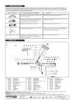
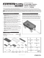
4.1.Remove the contents from the packaging and check them against the parts list overleaf (fig.1).
Ensure that all parts are present and not damaged.
If there are any problems, please contact your Sealey dealer.
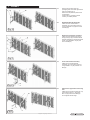
Fig.2
4.2.
Back Wheel Bracket Assembly.
Attach the back wheel bracket assembly (2) to the bottom panel (1),
using 2 bolts M8 x 16 (26) and 2 lock
nuts M8 (30).
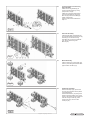
4.3.
Back wheel support bar assembly.
Attach the back wheel support bars, left (8) and right (9) to the back wheel bracket assembly (2) and to the bottom panel, using bolts M8 x 16 (26) and lock nuts M8 (30).
4.4.
Front wheel bracket assembly.
Attach the front wheel bracket
assembly (3) to the bottom panel (1), using bolt M8 x 16 (26) and lock nut
M8 (30).
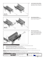
4.5.
Attach front support bar and turning fork.
Attach the front wheel support bar (18) to the bottom panel (1), using bolt
M8 x 16 (26) and lock nut M8 (30).
Do not tighten at this stage .
Fig.3
Fig.4
Fig.5
Original Language Version
CST806
Issue: 1 - 05/10/11