1
4.6.
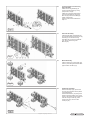
Turning bracket and connecting plate assembly.
Attach the turning bracket (6) to the front wheel bracket (3), using split pin Ø3 x 30 (36).
Attach the connecting plate (20) to the turning bracket (6), using bolt
M8 x 25 (27) and lock nut M8 (30). (Note: inset picture)
Tighten all the nuts and bolts from
step 4.4.
Fig.6
4.7.
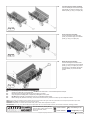
Flat Plate Assembly.
Place the flat plate (19) between the front wheel bracket (3) and the turning bracket (6). Fix both ends using
bolts M8 x 20 (37) and lock nuts M8 (30), fix the centre using bolt
M8 x16 (26).
4.8.
Wheel Assembly.
Place a wheel (13) on each axle and retain in place using flat washers Ø12 (28) and lock nuts M12 (31).
Fig.7
Fig.8
4.9.
Handle Bar Assembly.
Remove the R pin (35), pull out the pivot pin (34) and take out the plastic connecting sleeve.
Feed the handle bar (14) through the plastic connecting sleeve, line up the holes in the sleeve and the handle bar with the turning bracket (6), insert the pivot pin (34), secure it with the R pin (35).
Fig.9
Original Language Version
CST806
Issue: 1 - 05/10/11