1
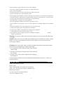
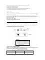
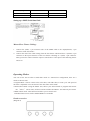
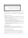
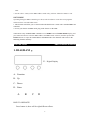
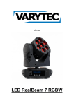
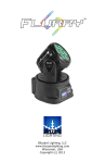
7X15W 5 in 1 LED Flat Par Light
User Instruction
1
CONTENTS
1. INSTRUCTION
Unpacking
Introduction
AC Power
Safety Instruction
Cleaning
2. FEATURE
3.
SET UP
3-Pin to 5-Pin Conversion Chart
Setting up a DMX Serial Data Link
Master/Slave Fixture Linking
4. OPERATING INSTRUCTIONS
Operating modes
Product overview
Program Mode & Sound Mode
Master-Slave Operation
Master-Slave Connections and Settings
DMX Mode
5. DMX CHANNEL SUMMARY
2
LED PAR LIGHT
Introduction
Unpacking: Thank you for purchasing our products. Every unit has been thoroughly tested
and has been shipped in perfect operating condition. Carefully check the shipping carton for
damage that may have occurred during shipping. If the carton appears to be damaged, carefully
inspect your fixture for any damage and be sure all accessories necessary to operate the unit has
arrived intact. In the case damage has been found or parts are missing, Save the carton and all
packing materials. In the event a fixture must be returned to the factory. It is important that the
fixture be returned in the original factory box and packing.
Introduction: The unit is a DMX intelligent LED par can. This light can be used in a stand alone
mode or connected in a Master/Slave configuration. The unit can also be controlled via DMX
controller. This light has four operating modes: Sound Active mode, stand alone mode,
Master/Slave and DMX control mode.
AC Power: This fixture has an auto-switching power supply that can accommodate a wide range
of input voltages. The only thing necessary to do before powering on the unit is to make sure the
line voltage you are applying is within the range of accepted voltages. This fixture will
accommodate between 90V and 240V AC. All fixtures must be powered directly off a switched
circuit and cannot be run off a rheostat (variable resistor) or dimmer circuit. Even if the rheostat or
dimmer channel is used solely for a 0-100% switch.
Safety Instructions:
Please read these instructions carefully, which includes important
information about the installation, usage and maintenance of this
product.
• To reduce the risk of electrical shock or fire, do not expose this unit
rain or moisture
• Do not spill water or other liquids into or on to your unit.
• Be sure that the local power outlet match that of the required voltage for your unit.
• Do not attempt to operate this unit if the power cord has been
frayed or broken. Do not attempt to remove or break off the ground
prong from the electrical cord. This prong is used to reduce the risk
of electrical shock and fire in case of an internal short.
• Disconnect from main power before making any type of connection.
• Do not remove the cover under any conditions. There are no user
serviceable parts inside.
• Never operate this unit when it’s cover is removed.
• Never plug this unit in to a dimmer pack
•Always be sure to mount this unit in an area that will allow proper
ventilation. Allow about 6” (15cm) between this device and a wall.
3
• Do not attempt to operate this unit, if it becomes damaged.
• This unit is intended for indoor use only, use of this product out`
doors voids all warranties.
• During long periods of non-use, disconnect the unit’s main power.
• Always mount this unit in safe and stable matter.
• Power-supply cords should be routed so that they are not likely to be walked on or pinched by
items placed upon or against them, paying particular attention to the point they exit from the unit.
• Cleaning -The fixture should be cleaned only as recommended by
the manufacturer. See page 3 for cleaning details.
• Heat -The appliance should be situated away from heat sources
such as radiators, heat registers, stoves, or other appliances (including amplifiers) that produce
heat.
• The fixture should be serviced by qualified service personnel when:
A. The power-supply cord or the plug has been damaged.
B. Objects have fallen, or liquid has been spilled into the appliance.
C. The appliance has been exposed to rain or water.
D. The appliance does not appear to operate normally or exhibits a
marked
change in performance.
Warning! To prevent or reduce the rist of electrical shock or fire, do not expose this unit to rain
or moisture.
Caution! There are no user serviceable parts inside this unit. Do not attempt any repairs yourself,
doing so will void your manufacturers warranty. In the unlikely event your unit may require
service please contact us.
Cleaning: Due to fog residue, smoke, and dust cleaning the internal and external optical lenses
must be carried out periodically to optimize light output.
1. Use normal glass cleaner and a soft cloth to wipe down the
outside casing.
2. Clean the external optics with glass cleaner and a soft cloth
every 20 days.
3. Always be sure to dry all parts completely before plugging
the unit back in.
Cleaning frequency depends on the environment in which the fixture operates (i.e. smoke, fog
residue, dust, dew).
LED PAR LIGHT
Features
Voltage: AC90V-245V/50-60Hz
Power: 120W
Color of LED: Red & Green & Blue & Amber&White
Lamp: 7pcs 15W LEDs ,Each LED have RGBWA colors
Beam angle: 40 degree
Life time: more than 100 thousand hours
Color effect: RGBWA mixing
4
Function Effect: dimmer, strobe, eotic, gradual change,sound activeted
Cooling mode: Natural Convection
Flicker free for television and film
Color: RGBA color can be mixed to more than 16.7million kinds of color
Control: DMX512, Master-slave, stand-alone, music Activate
Channel: 9CH
DMX signal Input/Output: 3-pin XLR
Feature: Cast Aluminum case, nice and wide application, less power consumption, high brightness,
stable performance, long life
Function: Color combination changer of the latest hybrid technology and excellent built-in
program, strobe, gradual, pulse, cycle, color selection, music activated, electronic linear Dimmer
Size: 290×160×270mm
N.W: 2.0KG G.W.: 2.5KG
Packaging : 640x340x290mm (4pcs/CTN)
LED PAR LIGHT
Set Up
Notice: Be sure to follow figures two and three when making your own cables. Do not use the
ground lug on the XLR connector. Do not connect the cable’s shield conductor to the ground lug
or allow the shield conductor to come in contact with the XLR’s outer casing. Grounding the
shield could cause a short circuit and erratic behavior.
Figure 3
XLR Pin Configuration
Pin 1 = Ground
Pin 2 = Data Compliment(negative)
Pin 3 = Data True(positive)
3-Pin to 5-Pin Conversion Chart:
Note! If you use a controller with a 5 pin DMX output connector,you will need to use a 5 pin to
3 pin adapter. The chart below details a proper cable conversion:
3-Pin to 5-Pin Conversion
Conductor
3 Pin Female(Output)
5 Pin Male(Input)
Ground/Shield
Pin 1
Pin 1
Data(-) signal
Pin 2
Pin 2
5
Data(+) signal
Pin 3
Pin 3
Not Used
Do not use
Not Used
Do not use
Setting up a DMX Serial Data Link:
Master/Slave Fixture Linking:
1. Connect the (male) 3 pin connector side of the DMX cable to the output(female) 3 pin
connector of the first fixture.
2. Connect the end of the cable coming from the first fixture which will have a (female) 3 pin
connector to the input connector of the next fixture consisting of a (male) 3 pin connector.
Then, proceed to connect from the output as stated above to the input of the following fixture
and so on.
Operating Modes:
You can use the unit in either a stand alone mode or a master/slave configuration, there are 4
modes to choose from:
• Program Mode - Choose a static color, color show, color fade show, or color cycle. The speed of
the show is adjustable. You can also have the unit strobe in this mode.
• Master/Slave Mode- Using the Master unit, choose your desired mode or program and connect
the “Slave” unit or units, All slaves will now follow the”Master” unit. But only one master.
• DMX control mode - This function will allow you to control each
individual fixtures traits with a standard DMX 512 controller
Product overview:
(Diagram I)
6
A
Button
<FN>
option
<UP>
order
<DOWN>
order
<ENTER>
B
C
D
Function
A
Used to access the mode or to return to a previous mode
B
Change the value of function you choosing in ascending
C
Change the value of function you choosing in descending
D
locate the function of which you want to change the value
Press the MODE button, you can browse all the function, such as AUTO RUN, DMX MODE,
SLAVE MODE, SOUND
While the function you want, for example, if DMX MODE, the ADDR & MODE can be adjusted.
You can press SETUP button to catch them, if MODE, it has 6 models, press UP & DOWN to
locate it.
Program Mode & Sound Mode:
In Program Mode you can pick your desired factory installed program; static color, color show,
color fade, or color cycle. You can apply a strobe effect to static colors, and control the speed of
the color shows, color fade, and color cycle.
1. Plug the fixture in and press the MODE button till 01 static display, you are now in program
model. Press UP and DOWN to find your desired effect.
2. If you have selected a static color, press SET UP button to enter into the flash rate (F:
000-100), press UP and DOWN to adjust and select your desired flash rate.
3. When you have chosen a color show (02-17), press SET UP button, the display will show
“S000-S100”, Press UP and DOWN button to adjust and set the speed. When the display
shows “F000-F100”, your desired program is running in strobe effect.
4. When the display shows Sound, the unit is working in sound active mode, and the sensitivity
(SENS: 00-99) is adjustable.
Master-Slave Operation:
This function will allows you to link units together to run in a Master-Slave mode. In
Master-Slave operation one unit will act as the controlling unit and the others will react to the
controlling units built-in programs. Any unit can act as a Master or as a Slave however, only one
unit can be programmed to act as the “Master.”
Master-Slave Connections and Settings:
1. Daisy chain your units via the XLR connector on the rear of the unit. Use standard XLR
microphone cables to link your units to-gether. Remember that the Male XLR connector is the
input and the Female XLR connector is the output. The first unit in the chain (master) will use
the female XLR connector only. The last unit in the chain will use the male XLR connector
only.
2. Using the Master unit, choose your desired mode or program and connect the “Slave” unit or
7
units.
3. Set the “Slave” unit(s) to the DMX address mode. They will now follow the”Master” unit.
DMX MODE:
Operating through a DMX controller give the user the freedom to create their own programs
tailored to their own individual needs.
1. This function will allow you to control each individual fixture’s traits with a standard DMX 512
controller.
2. To run your fixture in DMX mode, plug in the fixture via the XLR
connections to any standard DMX controller. Press MODE button till DMX MODE display, and
press SET UP button to enter the DMX address and DMX mode selection, and then press UP or
DOWN buttons to adjust the DMX address and DMX mode. The channels value refers to the
following channel summary.
LED PAR LIGHT
DMX Channels Summary
1. DIAGRAM :
E.Digital Display
A.Function
B.Up
C.Down
D.Enter
A
B
C
D
HOW TO OPERATE?
Press button A, there will be eight different effects.
8
The fist two numeric stands for functions (refer to Diagram II)
The last two numeric stands for DMX address, or speed.
You can modify it with B or C button..
D button is to confirm while you settled.
2. LED Display function cross-references,(D button is to
confirm while you settled)
No.
Display
1
D0001
2
CC00
3
CP00
4
DE00
5
6
BEBE
R220
7
G220
8
B220
9
W220
10
A220
Function
8CHs Address Code,(001—512)
Change the address code by B or C button
8Colors Changing,
(01—99)
Color change fast by B or C button
8colors gradual change,(01—99)
Speed of gradual changing by B or C button
8 Colors mixed changing, (01—99)
Select color. While change color, with B or C button
Music activate
Red color Changing,(000—255)
Change the color by B or C button
Green color Changing,(000—255)
Change the color by B or C button
Blue color Changing,(000—255)
Change the color by B or C button
White color changing, (000—255)
Change the color bu B or C button
Amber color changing, (000—255)
Change the color bu B or C button
3.DMX512 Channels
Channels
Function
CH.1
CH.2
Dimmer
Strobe
CH.3
Function Choose
Details
R、G、B、W dimmer,linear,dark →bright
R、G、B、W strobe,slow →fast
0—50:DMX 8 channels control;51--100:jump change;
101—150: gradual change, 151—200: pulse change,
201—255: Sound-active
9
CH.4
CH.5
CH.6
CH.7
CH.8
CH.9
Speed
Red
Green
Blue
White
Amber
Function Speed, slow →fast
R dimmer,linear,dark →bright
G dimmer,linear,dark →bright
B dimmer, linear, dark--bright
W dimmer, linear, dark--bright
A dimmer, linear, dark--bright
KEY POINT
Easy to operate, friendly design, no flicker while dimmer.stable quality.
Applicable to photograph, camera, and TV station as well.
10