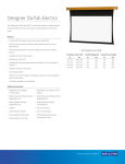
1
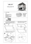
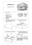
MASKED
Enclosed electrically unrolled screen
1. LIST OF ITEMS:
Electric screen,
Mounting elements – 2 pcs.,
Button switch,
Assembly kit,
Mounting instruction manual,
2. INSTALATION AND REGULATION:
A. Dimension table
B. Screw in elements C (pins) into elements B.
Then set the place of installation of the
screen on a solid ceiling - at distances as per
table D2. Use wall plugs and screws included
in the mounting kit.
C. Lift the screen by inserting pins marked C
into holes D.
Adjust nuts E to level the screen and then tighten
to ensure stability. Using magnets F, attach
masking elements G.
3.
ELECTRICAL CONNECTION:
A.
B. Electrical connection diagram for a screen
with the radio control option built-in.
PLEASE NOTE! The electrical connection
should be performed by a person with
appropriate certification and in accordance
with health and safety regulations.
C. SAFETY in transport: Before each transport
make sure that the screen is protected in
accordance with the guidelines.
D. Optional control:
The electric screen can be upgraded with
wireless radio (RC) or infrared (IR)
controllers.
When programming the stop positions, use
the programming manual.
4. REGULATION
POSITION - SCREEN UNROLLED
Additional adjustment of settings (other than factory defaults) is possible using the screw marked 1
(yellow). Only by authorised persons.
LIMITING SCREEN UNROLLING: In order to unroll the screen less than its factory setting, turn the key
to the left.
INCREASING SCREEN UNROLLING: In order to unroll the screen more than its factory setting (by 5 cm at
most), turn the key to the right. An increase in screen unrolling of more than 5 cm may cause
permanent damage to the screen.
POSITION - SCREEN ROLLED UP:
Additional adjustment of settings (other than factory defaults) is possible using the screw marked 2
(white). Only by authorised persons.
LIMITING EDGE BEAM UNROLLING: In order to unroll the lower edge screen beam less than its factory
setting, turn the key to the right.
INCREASING EDGE BEAM UNROLLING: In order to unroll the lower edge screen beam more than its
factory setting (by 5 cm at most), turn the key to the left. An increase in screen unrolling of more
than 5 cm may cause permanent damage to the screen.
5. TECHNICAL DATA:
Screen (surface):
URAN
URAN
URAN
URAN
(Matt White)
GREY (Cine Grey)
PROFESSIONAL (Professional Matt White)
PEARLESCENT (Pearlescent)
Image aspekt ratio:
Square
1:1
Power supply:
230V / 50 HZ
Manufacturer:
VIZ-ART Automation
tel.+48 22/6138899 www.viz-art.eu
Video
4:3
Cine
16:9
Rules of safe operation of
VIZ-ART AUTOMATION equipment
SAFETY INFORMATION
CAUTION: To ensure safety of the personnel, make sure to follow the guidelines provided
in this instruction manual. Keep the instruction manual for future reference.
•
•
•
•
•
•
•
•
•
•
•
•
•
•
Do not allow children to play with the device controller (switch or remote control).
Do not leave device controllers within the reach of children.
Inspect the equipment assembly periodically to identify and repair any damages.
If any damages are identified, do not use the equipment until the necessary repairs are
made.
Keep appropriate distance from the equipment during operation. In case of a failure, the
equipment may constitute a risk of injury or wounds.
Do not install any items other than those specified in the equipment instruction manual.
All installation and mounting works should be done by an engineer with appropriate licenses.
Inappropriate mounting may damage the product or cause injury.
Use only elements compliant with the mounting instructions.
It is prohibited to perform any steps that may damage the power supply cord or plug.
Do not modify the power cord, i.e. do not make any structural modifications, do not place the cord in immediate vicinity of hot objects, do not bend or twist the cord, do not
pull the cord, do not place any heavy objects on the cord, and do not coil the power
cord.
Using the equipment with a damaged power cord may cause electrocution or shorting of
the circuits and fire.
Do not touch the power cord or plug with wet hands.
Always follow the guidelines provided in this instruction manual and in the equipment
mounting instructions.
Before installing the equipment, make sure it is complete, free of defects, compliant
with your order, and has not sustained damage in transport.
INSTALLATION GUIDELINES
• The equipment should be installed by a qualified engineer, in accordance with the guidelines provided in the mounting instructions. Electrical connections should be made by a
specialist with an appropriate license.
• Install the equipment using screws and mounting elements appropriate for the conditions
of the installation, to which the lift is mounted, and stable, original auxiliary elements,
dedicated for the specific lift model.
• After mounting the equipment, before first use, check if it is mounted as per the instructions, and level. If the equipment is not level, adjust the mounting. Do not use equipment that is not properly installed.
• Do not modify or unscrew elements of the equipment, as this may cause a risk of permanent damage to the equipment and/or the safety of the users.
WARRANTY CONDITIONS
The warranty period for the device is 24 months from the date of purchase indicated on the original receipt.
1) The warranty period for the device's electric drive is 60 months.
2) The warrantor commits to fix free of charge damage suffered by a device delivered to the service point that demonstrates defects resulting from defects in
workmanship or materials, which become noticeable during the warranty period.
3) The warranty does not cover:
a) damage caused by use of the device in a manner other than that described in
the user manual,
b) damage caused by improper storage or transport,
c) mechanical damage,
d) abrupt changes in electrical grid voltage,
e) disassembly and reassembly,
4) Defects will be removed within 14 days from the date the device is accepted on
warranty at a service point.
5) Service point address
Manufactured after 13.08.2005.
Do not dispose of used electrical and electronic equipment together
with municipal waste, due to the presence of substances hazardous to
the environment in the equipment. Such devices should be delivered to
a collection point for recycling. Information on collection points is available from local government authorities or in stores.
DECLARATION OF CONFORMITY
VIZ-ART AUTOMATION
I hereby declare, with sole responsibility, that the products:
Elecric screens: SUPERNOVA, SUPERNOVA TENSION, MASKED, MASKED TENSION,
ELLIPSE, ELLIPSE TENSION, BUSINESS Plus,
to which this declaration relates, in accordance with:
the Low Voltage Directive 73/23EEC together with the modifications
of Directive 93/68/EEC
EMC Directive 89/336/EEC along with its amendments92/31/EEC,
93/68/EEC i 91/263/EEC
comply with the following European standards:
EN 60335-2-97 with reference to EN 60335-1
EN 55014-1, EN 55014-2, EN 61000-3-2, EN 61000-3-3
and are CE certified.