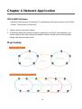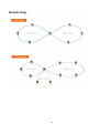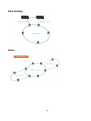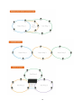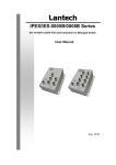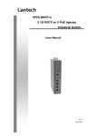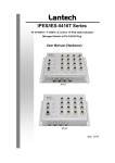
1
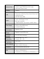
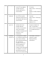
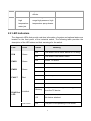
IES-3XXX IPES-3XXX IES-5XXX IP30-rated Series IP30-rated L2+ Industrial Managed Switch w/ITU G.8032 Ring User Manual (Hardware) Dec. 2015 Recommendation for Shielded network cables STP cables have additional shielding material that is used to reduce external interference. The shield also reduces the emission at any point in the path of the cable. Our recommendation is to deploy an STP network cable in demanding electrical environments. Examples of demanding indoor environments are where the network cable is located in parallel with electrical mains supply cables or where large inductive loads such as motors or contactors are in close vicinity to the camera or its cable. It is also mandatory to use an STP cable where the power device (like IP camera) is used outdoors or where the network cable is routed outdoors. Important Notice Lantech Communications Global, Inc. reserves the right to modify the equipment, its specification or this manual without prior notice, in the interest of improving performance, reliability, or servicing. At the time of publication all data is correct for the operation of the equipment at the voltage and/or temperature referred to. Performance data indicates typical values related to the particular product. No part of this documentation or information supplied may be divulged to any third party without the express written consent of Lantech Communications Global Inc. Products offered may contain software which is proprietary to Lantech Communications Global Inc. The offer or supply of these products and services does not include or infer any transfer of ownership. Interference Issues This Equipment has been tested and found to comply with the limits for a Class A digital device, pursuant to Part 15 of the FCC rules. These limits are designed to provide reasonable protection against harmful interference in a commercial or industrial installation. This equipment generates, uses, and can radiate radio frequency energy. It may cause harmful interference to radio communications if the equipment is not installed and used in accordance with the instructions. FCC Warning This Equipment has been tested and found to comply with the limits for a Class-A digital device, pursuant to Part 15 of the FCC rules. These limits are designed to provide reasonable protection against harmful interference in a residential installation. This equipment generates, uses, and can radiate radio frequency energy. It may cause harmful interference to radio communications if the equipment is not installed and used in accordance with the instructions. However, there is no guarantee that interference will not occur in a particular installation. If this equipment does cause harmful interference to radio or television reception, which can be determined by turning the equipment off and on, the user is encouraged to try to correct the interference by one or more of the following measures: Reorient or relocate the receiving antenna. Increase the separation between the equipment and receiver. Connect the equipment into an outlet on a circuit different from that to which the receiver is connected. Consult the dealer or an experienced radio/TV technician for help. CE Mark Warning This is a Class-A product. In a domestic environment this product may cause radio interference in which case the user may be required to take adequate measures. Content Chapter 1 Hardware Features ................................ 1 Chapter 2 Hardware Description............................ 4 2.1 IP Protection ................................................. 4 2.2 LED Indicators .............................................. 7 Chapter 3 Hardware Installation ............................ 9 3.1Hardware installation ......................................... 9 3.2 DIN-Rail Mounting........................................10 3.3 Wall Mount Plate Mounting ..........................12 3.4 Wiring the Power Inputs ...............................13 3.5 Wiring the Fault Alarm Contact ....................14 3.6 Cabling ........................................................15 Chapter 4 Network Application ............................ 18 ITU G.8032 Scheme ..............................................18 Ring Coupling ..........................................................18 Multiple Rings..........................................................19 Dual Homing ...........................................................20 Chain ......................................................................20 Chapter 5 Console Management.......................... 22 5.1 Connecting to the Console Port....................22 5.2 Login in the Console Interface......................23 Chapter 1 Hardware Features IEEE 802.3 10Base-T Ethernet IEEE 802.3u 100Base-TX IEEE802.3z Gigabit fiber IEEE802.3x Flow Control and Back Pressure IEEE802.3ad Port trunk with LACP IEEE802.1d Spanning Tree Standard IEEE802.1w Rapid Spanning Tree IEEE802.1s Multiple Spanning Tree IEEE 802.3ad Link Aggregation Control Protocol (LACP) IEEE 802.1AB Link Layer Discovery Protocol (LLDP) IEEE 802.1X User Authentication (Radius) IEEE802.1p Class of Service IEEE802.1Q VLAN Tag IEEE802.3at/af Power over Ethernet (PoE models) Switch Back-plane (Switching Fabric): Depends on model Architecture Packet throughput ability (Full-Duplex): Depends on model 14,880pps for Ethernet port Transfer Rate 148,800pps for Fast Ethernet port 1,488,000pps for Gigabit Ethernet port MAC Address 16K MAC address table 10/100/1000T: RJ-45 type connector 10/100Tx: RJ-45 type connector Mini-GBIC: 1000 SFP Sockets or 100/1000M SFP Sockets Connector 100M fiber: SC/ST type connector for single-mode or multimode type fiber cable Power & P-Fail connector: 1 x 6-pole terminal block Digital Input/Output: 1 x 6-pole terminal block RS-232 connector: 1 x RJ-45 type connector 1 10/100/1000T: 2-pair UTP/STP Cat. 5/ 5E / 6 cable Network Cable 10/100Tx: 2-pair UTP/STP Cat. 5/ 5E / 6 cable EIA/TIA-568 100-ohm (100m) Protocol CSMA/CD Per unit: Power 1 (Green), Power 2 (Green), P-Fail (Red) LED Ethernet port: Link/Activity (Green), Speed (Green); Giga-T: Link/Activity (Green) PoE FWD: Green( IPES) 1 Digital Input(DI): DI/DO Level 0: -30~2V/Level1: 10~30V Max. input current:8mA 1 Digital Output(DO): open collector to 40VDC, 200mA 48 VDC for 802.3af(IPES series) Power Supply 54VDC for 802.3at(IPES series) 9.5~56VDC (IES series) Power Consumption PoE Power Budget Operating Humidity Depends on model Depends on model (IPES series) 5% to 95% (Non-condensing) Operating Standard model: -20oC ~ 60oC Temperature -E model: -40oC ~ 75oC Storage Temperature Case Dimension Installation -40oC ~ 85oC Metal case. IP-30, 74(W) x 114 (D) x 152 (H) mm DIN rail and optional wall mount ear FCC Class A, CE EN61000-4-2, CE EN61000-4-3, CE EN- EMI 61000-4-4, CE EN61000-4-5, CE EN61000-4-6, CE EN61000-4-8, CE EN61000-4-11, CE 2 EN61000-4-12, CE EN61000-6-2, CE EN61000-6-4 Stability Testing IEC60068-2-32 (Free fall), IEC60068-2-27 (Shock), IEC60068-2-6 (Vibration) *For detail specifications, please refer to product datasheet. **The revise authority rights of product specifications belong to Lantech Communications Global, Inc. Lantech may make changes to specification and product descriptions at anytime, without notice. 3 Chapter 2 Hardware Description In this paragraph, it will describe the Industrial switch’s hardware spec, port, cabling information, and wiring installation. 2.1 IP Protection The IP Code, Ingress Protection Rating, sometimes also interpreted as International Protection Rating, classifies and rates the degree of protection provided against the intrusion (including body parts such as hands and fingers), dust, accidental contact, and water in mechanical casings and with electrical enclosures. It is published by the International Electrotechnical Commission (IEC) Solid particle protection The first digit indicates the level of protection that the enclosure provides against access to hazardous parts (e.g., electrical conductors, moving parts) and the ingress of solid foreign objects. Level 0 Object size Effective against protected against — No protection against contact and ingress of objects Any large surface of the body, such as the back of a 1 >50 mm hand, but no protection against deliberate contact with a body part 2 >12.5 mm Fingers or similar objects 3 >2.5 mm Tools, thick wires, etc. 4 >1 mm Most wires, screws, etc. Ingress of dust is not entirely prevented, but it must 5 Dust protected not enter in sufficient quantity to interfere with the satisfactory operation of the equipment; complete 4 protection against contact 6 No ingress of dust; complete protection against Dust tight contact Liquid ingress protection The second digit indicates the level of protection that the enclosure provides against harmful ingress of water. Level 0 1 2 Protected Testing for against Not Details — — Dripping Dripping water (vertically Test duration: 10 minutes water falling drops) shall have no Water equivalent to 1 mm harmful effect. rainfall per minute Dripping Vertically dripping water Test duration: 10 minutes water when shall have no harmful effect Water equivalent to 3 mm tilted up to when the enclosure is tilted rainfall per minute 15° at an angle up to 15° from protected its normal position. 3 4 Spraying Water falling as a spray at Test duration: 5 minutes water any angle up to 60° from Water volume: 0.7 litres per the vertical shall have no minute harmful effect. Pressure: 80–100 kPa Splashing Water splashing against Test duration: 5 minutes of water the enclosure from any Water volume: 10 litres per direction shall have no minute harmful effect. Pressure: 80–100 kPa 5 5 Water jets Water projected by a Test duration: at least nozzle (6.3 mm) against 15 minutes enclosure from any Water volume: 12.5 litres per direction shall have no minute harmful effects. Pressure: 30 kPa at distance of 3 m 6 Powerful Water projected in powerful Test duration: at least water jets jets (12.5 mm nozzle) 3 minutes against the enclosure from Water volume: 100 litres per any direction shall have no minute harmful effects. Pressure: 100 kPa at distance of 3 m 7 Immersion Ingress of water in harmful Test duration: 30 minutes up to 1 m quantity shall not be Immersion at depth of at possible when the least 1 m measured at enclosure is immersed in bottom of device, and at least water under defined 15 cm measured at top of conditions of pressure and device time (up to 1 m of submersion). 8 Immersion The equipment is suitable Test duration: continuous beyond 1 m for continuous immersion in immersion in water water under conditions Depth specified by which shall be specified by manufacturer the manufacturer. Normally, this will mean that the equipment is hermetically sealed. However, with certain types of equipment, it can mean that water can enter but only in such a manner that 6 it produces no harmful effects. 9 — Powerful Protected against close- high range high pressure, high temperature temperature spray downs. water jets 2.2 LED Indicators The diagnostic LEDs that provide real-time information of system and optional status are located on the front panel of the industrial switch. The following table provides the description of the LED status and their meanings for the switch. LED Color R.M Green PWR1 PWR2 FAULT Status On The switch unit is owner switch of ITU-Ring Off The switch is not owner switch On Power 1 is active Off Power 1 is inactive On Power 2 is active Off Power 2 is inactive On Power or port failure Off No failure On A network device is detected. Green Green Red Blinking RJ45 Port Meaning Link/Ack The port is transmitting or receiving packets from the TX device. LED PoE FWD Off No device attached Off The port is not operating in PoE mode. 7 (For PoE model) On On SFP Port Blinking The port is operating in PoE mode. A network device is detected. The port is transmitting or receiving packets from the TX device. LED Off No device attached. 8 Chapter 3 Hardware Installation 3.1Hardware installation 1. Unpack the Industrial switch 2. Check if the DIN-Rail is screwed on the Industrial switch or not. If the DIN-Rail is not screwed on the Industrial switch, please refer to DIN-Rail Mounting section for DINRail installation. If users want to wall mount the Industrial switch, please refer to Wall Mount Plate Mounting section for wall mount plate installation. NOTE: Wall mount kits are optional accessories. 3. To hang the Industrial switch on the DIN-Rail track or wall. 4. Power on the Industrial switch. Please refer to the Wiring the Power Inputs section for knowing the information about how to wire the power. The power LED on the Industrial switch will light up. Please refer to the LED Indicators section for indication of LED lights. 5. Prepare the twisted-pair, straight through Category 5 cable for Ethernet connection. 6. Insert one side of RJ-45 cable (category 5) into the Industrial switch Ethernet port (RJ-45 port) and another side of RJ-45 cable (category 5) to the network device’s Ethernet port (RJ-45 port), ex: Switch PC or Server. The UTP port (RJ-45) LED on the Industrial switch will light up when the cable is connected with the network device. Please refer to the LED Indicators section for LED light indication. [NOTE] Make sure that the connected network devices support MDI/MDI-X. If it does not support, use the crossover category-5 cable. 7. When all connections are set and LED lights all show in normal, the installation is complete. 9 3.2 DIN-Rail Mounting The DIN-Rail is screwed on the industrial switch when out of factory. If the DIN-Rail is not screwed on the industrial switch, please see the following pictures to screw the DINRail on the switch. Follow the steps below to hang the industrial switch. 10 1. First, insert the top of DIN-Rail into the track. 2. Then, lightly push the DIN-Rail into the track. 3. Check if the DIN-Rail is tightened on the track or not. 4. To remove the industrial switch from the track, reverse above steps. 11 3.3 Wall Mount Plate Mounting Follow the steps below to mount the industrial switch with wall mount plate. 1. Remove the DIN-Rail from the industrial switch; loose the screws to remove the DINRail. 2. Place the wall mount plate on the rear panel of the industrial switch. 3. Use the screws to screw the wall mount plate on the industrial switch. 4. Use the hook holes at the corners of the wall mount plate to hang the industrial switch on the wall. 5. To remove the wall mount plate, reverse the above steps. NOTE : Wall mount kits are optional accessories 12 3.4 Wiring the Power Inputs Please follow the steps below to insert the power wire. 1. Insert AC or DC power wires into the contacts 1 and 2 for power 1, or 5 and 6 for power. 2. Tighten the wire-clamp screws for preventing the wires from loosing. [NOTE] The wire gauge for the terminal block should be in the range between 12 ~ 24 AWG. 13 3.5 Wiring the Fault Alarm Contact The fault alarm contacts are in the middle of the terminal block connector as the picture shows below. Inserting the wires, the switch will detect the fault status of the power failure, or port link failure (available for managed model) and then forms an open circuit. The following illustration shows an application example for wiring the fault alarm contacts. Insert the wires into the fault alarm contacts [NOTE] The wire gauge for the terminal block should be in the range between 12 ~ 24 AWG. 14 3.6 Cabling Use four twisted-pair, Category 5e or above cabling for RJ-45 port connection. The cable between the switch and the link partner (switch, hub, workstation, etc.) must be less than 100 meters (328 ft.) long. Fiber segment using single-mode connector type must use9/125 µm single-mode fiber cable. User can connect two devices in the distance up to 30km. Fiber segment using multi-mode connector type must use 50 or 62.5/125 µm multimode fiber cable. User can connect two devices up to 2kmdistances. Gigabit / 100M SFP port: The small form-factor pluggable (SFP) is a compact optical transceiver used in optical communications for both telecommunication and data communications. The SFP slots supporting Gigabit speed up to 1000Mbps. –DSFP/-DFT models support dual speed 100M or 1000Mbps. They are used for connecting to the network segment with single or multi-mode fiber. You can choose the appropriate SFP transceiver to plug into the slots. Then use proper multi-mode or single-mode fiber according to the transceiver. With fiber optic, it transmits at speed up to 1000 Mbps or dual speed (-DSFP/-DFT models) and you can prevent noise interference from the system. To connect the transceiver and LC cable, please follow the steps shown below: First, insert the transceiver into the SFP module. Notice that the triangle mark is the bottom of the module. Transceiver to the SFP module 15 Transceiver Inserted Second, insert the fiber cable of LC connector into the transceiver. LC connector to the transceiver 16 To remove the LC connector from the transceiver, please follow the steps shown below: First, press the upper side of the LC connector to release from the transceiver and pull it out. Remove LC connector Second, push down the metal loop and pull the transceiver out by the plastic handle. Pull out from the transceiver 17 Chapter 4 Network Application ITU G.8032 Scheme Lantech G.8032 protocol is following ITU (International Telecommunication Unit) G.8032 v2 draft. The benefits of G.8032 are: 1. <50ms recovery time when failover 2. G.8032 has defined the protocol scheme, parameters, functions, test measures to be unified that the users can evaluate the possible network infrastructure without literally testing each brand in large scale. Ring Coupling 18 Multiple Rings 19 Dual Homing Chain 20 21 Chapter 5 Console Management 5.1 Connecting to the Console Port The supplied cable which one end is RS-232 connector and the other end is RJ-45 connector. Attach the end of RS-232 connector to PC or terminal and the other end of RJ-45 connector to the console port of the switch. The connected terminal or PC must support the terminal emulation program. DB9 Connector RJ-45 Connector NC 1 Orange/White 2 2 Orange 3 3 Green/White NC 4 Blue 5 5 Blue/White NC 6 Green NC 7 Brown/White NC 8 Brown Pin assignment 22 5.2 Login in the Console Interface When the connection between Switch and PC is ready, turn on the PC and run a terminal emulation program or Hyper Terminal and configure its communication parameters to match the following default characteristics of the console port: Baud Rate:115200 bps Data Bits: 8 Parity: none Stop Bit: 1 Flow control: None The settings of communication parameters Having finished the parameter settings, click ‘OK’. When the blank screen shows up, press Enter key to have the login prompt appears. Key in ‘admin’ (default value) for both User name and Password (use Enter key to switch), then press Enter and the Main Menu of console management appears. Please see below figure for login screen. 23 Console login interface ===============Notice=============== For web-based management, please refer to our “Software Management Manual” at http://www.lantechcom.tw/global/eng/support-downloads.html 24