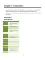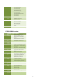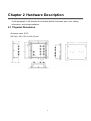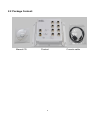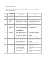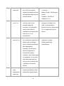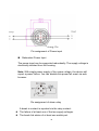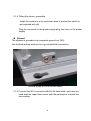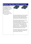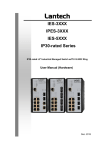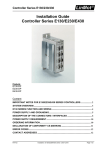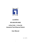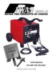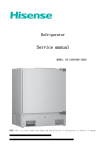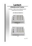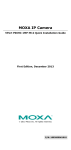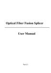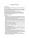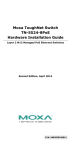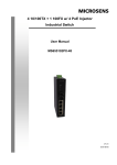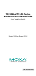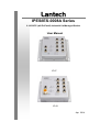
1
IPES/IES-0008A Series 8 10/100TX (w/8 PoE at/af) Industrial Un-Managed Switch User Manual IP-67 IP-43 Apr. 2014 Recommendation for Shielded network cables STP cables have additional shielding material that is used to reduce external interference. The shield also reduces the emission at any point in the path of the cable. Our recommendation is to deploy an STP network cable in demanding electrical environments. Examples of demanding indoor environments are where the network cable is located in parallel with electrical mains supply cables or where large inductive loads such as motors or contactors are in close vicinity to the camera or its cable. It is also mandatory to use an STP cable where the power device (like IP camera) is used outdoors or where the network cable is routed outdoors. Important Notice Lantech Communications Global, Inc. reserves the right to modify the equipment, its specification or this manual without prior notice, in the interest of improving performance, reliability, or servicing. At the time of publication all data is correct for the operation of the equipment at the voltage and/or temperature referred to. Performance data indicates typical values related to the particular product. No part of this documentation or information supplied may be divulged to any third party without the express written consent of Lantech Communications Global Inc. Products offered may contain software which is proprietary to Lantech Communications Global Inc. The offer or supply of these products and services does not include or infer any transfer of ownership. Interference Issues This Equipment has been tested and found to comply with the limits for a Class A digital device, pursuant to Part 15 of the FCC rules. These limits are designed to provide reasonable protection against harmful interference in a commercial or industrial installation. This equipment generates, uses, and can radiate radio frequency energy. It may cause harmful interference to radio communications if the equipment is not installed and used in accordance with the instructions. FCC Warning This Equipment has been tested and found to comply with the limits for a Class-A digital device, pursuant to Part 15 of the FCC rules. These limits are designed to provide reasonable protection against harmful interference in a residential installation. This equipment generates, uses, and can radiate radio frequency energy. It may cause harmful interference to radio communications if the equipment is not installed and used in accordance with the instructions. However, there is no guarantee that interference will not occur in a particular installation. If this equipment does cause harmful interference to radio or television reception, which can be determined by turning the equipment off and on, the user is encouraged to try to correct the interference by one or more of the following measures: Reorient or relocate the receiving antenna. Increase the separation between the equipment and receiver. Connect the equipment into an outlet on a circuit different from that to which the receiver is connected. Consult the dealer or an experienced radio/TV technician for help. CE Mark Warning This is a Class-A product. In a domestic environment this product may cause radio interference in which case the user may be required to take adequate measures. Content Chapter 1 Introduction ........................................... 4 Specification ........................................................... 4 Chapter 2 Hardware Description............................ 7 2.1 Physical Dimension ....................................... 7 2.2 Package Content: ......................................... 9 2.3 IP Protection ................................................10 2.4 LED Indicators .............................................13 Chapter 3 Hardware Installation .......................... 14 Chapter 1 Introduction Lantech IES-0008A & IPES-0008A (IP67/IP43) series is a high performance IP67/IP43 industrial switch with 8x10/100TX (w/8 PoE at/af injectors-IPES model)by M12 connectors which provides L2 wire speed and advanced security function for connecting PD network. Specification IES-0008A series Hardware Specification IEEE IEEE802.3 10BASE-T Ethernet Standard IEEE802.3u 100BASE-T Ethernet IEEE802.3x Flow Control and Back Pressure Transfer 14,880pps for Ethernet port Rate 148,800pps for Fast Ethernet port Mac 8K MAC address table Address Connector 10/100T: 8 x M12, 4 -pole D-coded, Female with auto MDI/MDI-X function Power connector: 1 x M12, 5-pole Acoded, Male Protocol CSMA/CD LED Per unit: Power 1 (Green), Power 2 (Green), Ethernet: Link/Activity (Green) Power Redundant power DC 12V ~72V Supply HV model power 85~265VAC/110V~300VDC Power 6Watts Consumpti on Operating 5% to 95% (Non-condensing) Humidity Operating -40°C ~ 75°C (-40°F ~ 167°F) Temperatu re Storage -40°C ~ 85°C (-40°F ~ 185°F) Temperatu re Case Aluminum case. IP-67, Dimension 215mm(W)x185mm(H)x71mm(D) Aluminum case, IP-43 202mm(W)x172mm(H)x62.5mm(D) Weight IP67:2kgs ; IP43: 750gs Installation Din Rail, Wall Mount Design EMC FCC Class A, 4 CE EN61000-4-2 (ESD), CE EN61000-4-3 (RS), CE EN-61000-4-4 (EFT), CE EN61000-4-5 (Surge), CE EN61000-4-6 (CS), CE EN61000-4-8 (Magnetic Field), CE EN61000-6-2, CE EN61000-6-4 Stability IEC61373 (Shock), Testing IEC60068-2-32 (Free fall), IEC61373 (Vibration) Standard EN50155 Compliant* EN50121-3-2 Compliant* EN50121-4 Compliant* NEMA TS2 Compliant* E-Mark* Warranty 5 years *Pending IPES-0008A series Hardware Specification IEEE IEEE802.3 10BASE-T Ethernet Standard IEEE802.3u 100BASE-T Ethernet IEEE802.3x Flow Control and Back Pressure IEEE802.3at/af Power over Ethernet Transfer 14,880pps for Ethernet port Rate 148,800pps for Fast Ethernet port Mac 8K MAC address table Address Connector 10/100T: 8 x M12, 4 -pole D-coded, Female with auto MDI/MDI-X function Power connector: 1 x M23, 5-pole Acoded, Male Relay contact : 1 x M12 5-pole A-coded Protocol CSMA/CD LED Per unit: Power 1 (Green), Power 2 (Green), Ethernet: Link/Activity (Green) PoE Pin RJ-45 port # 1~#8 support IEEE Assignme 802.3af/at End-point, Alternative A mode. nt Per port provides 15.4W/30W ability. Positive (VCC+): RJ-45 pin 1,2. Negative (VCC-): RJ-45 pin 3,6. Power 12~56VDC for Ethernet Data Supply 12~56VDC for PoE feeding -48VDC is available for single power input 72VDC for Data (10W); PoE (100W) Power 10W Consumpti on Power 240W for 802.3at 54V input Budget 120W for 802.3af 48V input 90W for 12V input 120W for 24V input 100W for 72V Input Operating 5% to 95% (Non-condensing) Humidity Operating -40°C ~ 75°C (-40°F ~ 167°F) Temperatu re 5 Storage -40°C ~ 85°C (-40°F ~ 185°F) Temperatu re Case Aluminum case. IP-67, Dimension 215mm(W)x185mm(H)x71mm(D) Aluminum case, IP-43 202mm(W)x172mm(H)x62.5mm(D) Weight IP67:2kgs ; IP43: 750gs Installation Din Rail, Wall Mount Design EMC FCC Class A, CE EN61000-4-2 (ESD), CE EN61000-4-3 (RS), CE EN-61000-4-4 (EFT), CE EN61000-4-5 (Surge), CE EN61000-4-6 (CS), CE EN61000-4-8 (Magnetic Field), CE EN61000-6-2, CE EN61000-6-4 Stability IEC61373 (Shock), Testing IEC60068-2-32 (Free fall), IEC61373 (Vibration) Standard EN50155 Compliant EN50121-3-2 Compliant EN50121-4 Compliant NEMA TS2 Compliant* E-Mark* Warranty 5 years *Pending 6 Chapter 2 Hardware Description In this paragraph, it will describe the Industrial switch’s hardware spec, port, cabling information, and wiring installation. 2.1 Physical Dimension Aluminum case. IP-67, 285 (W) x 201.4 (D) x 84.4 (H) mm 7 Port description of IP-67 series switch Aluminum case. IP-43, 273 (W) x 188.4(D) x 84.4 (H) mm **The port description of IP-43 model is the same as of IP-67 one. 8 2.2 Package Content: Manual CD Product 9 Console cable 2.3 IP Protection The IP Code, Ingress Protection Rating, sometimes also interpreted as International Protection Rating, classifies and rates the degree of protection provided against the intrusion (including body parts such as hands and fingers), dust, accidental contact, and water in mechanical casings and with electrical enclosures. It is published by the International Electrotechnical Commission (IEC) Solid particle protection The first digit indicates the level of protection that the enclosure provides against access to hazardous parts (e.g., electrical conductors, moving parts) and the ingress of solid foreign objects. Level 0 Object size Effective against protected against — No protection against contact and ingress of objects Any large surface of the body, such as the back of a 1 >50 mm hand, but no protection against deliberate contact with a body part 2 >12.5 mm Fingers or similar objects 3 >2.5 mm Tools, thick wires, etc. 4 >1 mm Most wires, screws, etc. Ingress of dust is not entirely prevented, but it must 5 Dust protected not enter in sufficient quantity to interfere with the satisfactory operation of the equipment; complete protection against contact 6 Dust tight No ingress of dust; complete protection against contact 10 Liquid ingress protection The second digit indicates the level of protection that the enclosure provides against harmful ingress of water. Level 0 1 2 Protected Testing for against Not Details — — Dripping Dripping water (vertically Test duration: 10 minutes water falling drops) shall have no Water equivalent to 1 mm harmful effect. rainfall per minute Dripping Vertically dripping water Test duration: 10 minutes water when shall have no harmful effect Water equivalent to 3 mm tilted up to when the enclosure is tilted rainfall per minute 15° at an angle up to 15° from protected its normal position. 3 4 5 Spraying Water falling as a spray at Test duration: 5 minutes water any angle up to 60° from Water volume: 0.7 litres per the vertical shall have no minute harmful effect. Pressure: 80–100 kPa Splashing Water splashing against Test duration: 5 minutes of water the enclosure from any Water volume: 10 litres per direction shall have no minute harmful effect. Pressure: 80–100 kPa Water projected by a Test duration: at least nozzle (6.3 mm) against 15 minutes enclosure from any Water volume: 12.5 litres per direction shall have no minute harmful effects. Pressure: 30 kPa at distance Water jets of 3 m 11 6 Powerful Water projected in powerful Test duration: at least water jets jets (12.5 mm nozzle) 3 minutes against the enclosure from Water volume: 100 litres per any direction shall have no minute harmful effects. Pressure: 100 kPa at distance of 3 m 7 Immersion Ingress of water in harmful Test duration: 30 minutes up to 1 m quantity shall not be Immersion at depth of at possible when the least 1 m measured at enclosure is immersed in bottom of device, and at least water under defined 15 cm measured at top of conditions of pressure and device time (up to 1 m of submersion). 8 Immersion The equipment is suitable Test duration: continuous beyond 1 m for continuous immersion in immersion in water water under conditions Depth specified by which shall be specified by manufacturer the manufacturer. Normally, this will mean that the equipment is hermetically sealed. However, with certain types of equipment, it can mean that water can enter but only in such a manner that it produces no harmful effects. 9 Powerful Protected against close- high range high pressure, high temperature temperature spray downs. water jets 12 — 2.4 LED Indicators The diagnostic LEDs that provide real-time information of system and optional status are located on the front panel of the industrial switch. The following table provides the description of the LED status and their meanings for the switch. LED Color PWR1 Green PWR2 FAULT Status Meaning On Power 1 is active Off Power 1 is inactive On Power 2 is active Off Power 2 is inactive On Power or port failure Off No failure On A network device is detected. Green Red Link/Ack P1 ~ P8 Blinking Off PoE(1~8)(IP ES) On Off The port is transmitting or receiving packets from the TX device. No device attached The port is operating in PoE mode.(IPES) The port is not operating in PoE mode.(IPES) 13 Chapter 3 Hardware Installation 3.1Hardware installation 3.1.1Unpack switch and check the accessory with packing content list 3.1.2 Mount the switch on desired position. For the best ventilation, it is suggested to mount the switch on metallic surface. 3.1.3 Connect the M23/M12 connector of power input. The PoE power supply for IPES-0008A series is connected via a 5-pole M23 female connector while IES-0008A is with a 5-pole M12 female connector. Voltage of Power Input For IPES-0008A series, the voltage of power input should use 48VDC to feed power IEEE 802.3af standardized devices or 54VDC for IEEE 802.3at standardized ones. For IPES-0008A-12V series, the power input voltage can be from 9.2V to 56VDC to feed power on both the 802.3af and 802.3at standardized devices. With IPES-0008A-72V series, the power input voltage can be from 72V to feed power on both 802.3af/at standardized devices. IES0008A series can accept power input ranging from 9.2V~72V(12V~72V) to be powered. Please make sure that the external power supply unit you use to provide the PoE voltage meet the following criteria: The output voltage of power supply must exceed 48VDC for 802.3af and 53VDC for 802.3at operation(with IPES-0008A-72V, only 72VDC can power both the 802.3af and 802.3at PD.) The power consumption can satisfy the total power request from all PD devices required. 14 Pin assignment of Power input Redundant Power Input The power input can be supported redundantly. The supply voltage is electrically isolated from the housing. Note: With single power supply of the mains voltage, the device will report a power failure. You can disable this power fail event via web browser. Pin assignment of alarm relay A break in contact is reported via the relay contact : The failure of at least one of the two supply voltages. The break link status of at least one switch port. 15 3.1.4 Fitting the device, grounding Install the system in a dry and clean area to protect the switch to get exposed with dirt. Plug the connector to the power supply plug then turn on the power supply. Ground The chassis is grounded via a separate ground nut (M3). Use toothed locking washers for a good electrical connection. Ground screw of IPES-0008A switch 3.1.5 Connect the M12 connector with RJ-45 data cable, ports are not used shall be caped that comes with the package to insulate the surrounding. 16 Pin assignment of M12 10/100Tx network connector 3.1.6 Check the status of LED, make sure the switch was in working status. Note: The protection class IP67/IP43 is only achieved when bolted together. The other components attaching to the system have to meet with the IP67/IP43 protection class in order to reach the whole system IP 67/IP43 protection. 17 Empty ports must be sealed with the protective caps supplied. 18