1
United States Patent [19]
[11]
[45]
Hardin, Sr. et al.
[54]
COMPUTERIZED HANDWRITING
DUPLICATION SYSTEM
[75] Inventors: William F. Hardin, Sr., Sterling;
4,817,034
Date of Patent:
Mar. 28, 1989
4,656,662
4,672,677
4/1987 Fillirnan C! 111. ....................... .. 382/3
6/1987 Yamakawa .............. .. 31:2/13
4,679,241
7/1987
1.111115 ................................... .. 382/13
Pn'mary Examiner-Gary V. Harkcom
William M. Mack, Jr., Reston, both
Assistant Examiner-Randy W. Lacasse
of Va.
'
Attorney, Agent, or Firm-Larson and Taylor
[73] Assrgnee: E.S.P. Systems, Inc., Locust Grove,
va_
[57]
No‘: 828,400
[2 1] APPL
_
[22] Fdcd‘
Feb’ 11’ 1986
[51] Int. 01.4 .............................................. .. G06F 3/13
[52] US. Cl. ...................................... .. 364/900; 382/2;
ABSTRACI‘
A computerized handwriting duplication system in
cludes a general purpose, programmable, digital mi
crocomputer having a buffer memory, a program mem
Orv for a computer Program, and a memory for storing
the digital representation of the coordinates of a signa
382/13; 340/728; 178/18
[53]
Patent Number:
ture. The system also includes a digitizer pad for pro
Field of Search ............... .. 382/2, 13, 59; 178/18,
viding to the microcomputer as raw data the X and Y
178/20; 340/712, 728; 364/200 MS File, 900
MS File
coordinates of points travelled by a pen writing a signa
ture thereon and for providing a keyboard-type of input
References Cited
information to the microcomputer.lThe computer pro
Us‘ PATENT DOCUMENTS
gram comprises routines for receiving a large string of
bytes of serial raw data in absolute distances; for con
[56]
2,518,694 8/1950 Jannopouio ....................... .. 250/208
3,111,646 1l/l963 Harmon ......... ..
verting the data to relative distances beginning from a
340/1463
pfgdetermjned Starting point and than from the previ.
21332:; i/
4’o70’649 ‘41978
ous adjacent coordinate point; for compressing the data
by deleting all coordinate information generated when
4:o71:690 V1973
the cursor pen ‘is out of contact with the digitizer pad;
4,252,231 4/1931
4,319,331 3/1982
4,344,135 8/1982
and for smoothing the handwriting by determining new
coordinates for all points falling outside a predeter
mined locus. An X-Y plotter is connected to the mi
i'igg'gz‘l 1:’
crocomputer and is supplied with plotting commands
4'542'4g 92985
and data points which the computer has re?ned from
4:550:43‘; 10/1935
the raw data supplied to it by the digitizer pad.
4,641,354 2/1987
4,653,107 3/1987
9 Claims, 10 Drawing Sheets
46
VIDEO
MONITOR
PAPER
‘J
/
5O
FEEDER
f
RAM BUFFER
[2
MICROCOMPUTER
/ 48
PROGRAM
MEMORY
‘
PLOTTER
D|$K
MEMORY
2O
DIGITIZER
PAD
J‘
'0
22
/ l4
/ I6
I8
US. Patent
Mar. 23, 1989
Sheet 1 0f 10
4,817,034
46
I0
VIDEO
@
J 50
PAPER
FEEDER
/
‘2
<——l_)
f
MICRQ-
/48
COMPUTER
PLOTTER
,
502
lE’MROGFZAM
/I6
mSK
MEMORY
/ '8
EMORY
2
O
DIGITIZER
PAD
/ l4
RAM BUFFER
—A
22
504
US. Patent
Mar. 28, 1989
4,817,034
Sheet 2 0f 10
[26
5
E]
a:
44»
38 ~
40
EBJEJI]NQEgJEUlJNDi'E T
(
YES
NO
42 AH - RESET
Sig/202w“ 133/5 2am y
p
:32
K20
F762
US. Patent
Mar. 28, 1989
Sheet 3 of 10
4,817,034
MAIN MENU ROUTINE
(240)
@2'
80
''\-INTRODUCTION
/
USE PREVIOUS
SIGNATURE
'02
YES
TO FIG. 5
RECORD A NEW
SIGNATURE
YES
@FMI07FIG. 5
REVIEW SIGNATURE
LOG
YES
F/G 4
ERASE A
SIGNATURE
/
FM FIG. 4
To FIG. 4
L06 ROUTINE
IR [~84
V308
DISPLAY
LOG
J YES,NO, RESET
‘
TOUCHED
£76? 11
US. Patent
Mar. 28, 1989
Sheet 4 of 10
4,817,034
USE ROUTINE
TO FIG. 4
FM FIG 4
I02
R
84
DISPLAY
SIGNATURES
0" F'LE
~|O4
IS DESIRED
SIGNATURE
ON FILE
NO
log\
[07
70 F/G. 4
RESET
ENTER ID
NO,
TOUCI-IED
OF DESIRED
SIGNATURE
TOUCHED
ENTER
TOUCHED
SIGNATURE
PRESENT?
Q
YES
"RESET"
TOUCHED
IS
ENTER
\"3
INSERT PROPER
SECURITY
‘NO
“DISSK'I xNEENTOOIiCH
ENTER TOUCHED
NO ISJglgJMBER OF TRIES
CODE
TOUCHED
YE
CODE
H
'
84
CORRECT?
H64
YES
?iviso
NO
RESET
TOUCHED
FM FIG. 6 OR 7
g)
TOUCHED
ENTEF;\ ENTER NUMBER
TOUCHED
OF SIGNATURES
TO BE WRITTEN
C2: A24
TO FIG. 6
TO FIG. 7
H65
US. Patent
Mar. 28, 1989
T0 F/G- 4
Sheet 5 0f 10
SINFEELE
TSIGNATURE
SEB'RISGTHEJ
FM F/G- 5
Elm
U‘
A2
RESET
TOUCHED
4,817,034
I24
“b?é‘élé
SIGNATURE
8
2.
Is TO BE
PLACED
84
YES
'
TO FIG. 4
I34
PRE FEED
PAPER
/
'36
NO
YES
FEED PAPER 140
‘NOT READY
ROUTINE
'38
AND
PRINT
PEIIIIPTED
C
|42\
_ NO
RESET
TOUCHED
HALT, CHECK -
IF TO BE
HALTED
I44
YES (TIMEO)
A A2
'
NO
HALTE5|46
YES
REusE sAME
SIGNATURE
US. Patent
Mar. 28, 1989
Sheet 6 0f 10
MULTI SIGNATURE
REPLICATION
SUBROUTINE
FOR FIG. 5
TO FIG. 4
(‘RI/~84
4,817,034
[A3 H26
I
LOCATE WHERE
.\
,,
RESET
TOUCHED
SIGNATURE IS
I28
TO BE PLACED
_
I30
IN
YE S
PRE- FEED
PAPER
'34
I36
/
NO
I38
NOT READY
ROUTINE
YES
FEED
PAPER AND
PRINT
/ I40
SEL ECTED
NUMBER
PRINTED
" No" OR "RESET"
JOB
TOUCHED wI-ETED
YES
TOUCHED
REUSE
SAME
SIGNATURE
TO F/G. 4
US. Patent
Mar. 28, 1989
Sheet 7 of 10
4,817,034
SIGNATURE RECORDING
ROUTINE
FM FIG. 4
202
TO FIG. 4
R
[BJ
84
INITIALIZE,
\
GIVE START
20_4
SIGNAL AND
RECORD DATA
FIG. 8A
RECORDING
COMPLETED
‘
RESET
TOUCHED
PROCESS
DATA AND
TEST DATA
FIG. 88
FM FIG, IO
NO
DATA
ACCEPTED
NO OR
RESET
SAMPLE
PLOT
DESIRED
238
PREFEED
PAPER
REDO
SIGNATURE
NO
f
84
OR
RESET
TO FIG. 4
FEED AND
242
PRINT
RESET
244
/\
SAVE
N
O
\
Y ES
246
TOP/6.9
248
B3
TO F/G. I0
8
US. Patent
Mar. 28, 1989
Sheet 8 of 10
CAPTURE
@/ SUBROUTINE
/ INITIALIZE
eIvE sTART
2 6
TONE AND
RECEIVE DATA
NO, BUT
PROXIMATE
208
2I21
PEN
DOWN
I
i
PREFACE
X-Y cooRD.
WITH "0"
NO‘
2|
YES 2I6
/o
I
PREFACE
x-v cooRD.
WITH "I"
LOAD
ZERO
'————+II
l____>
sToRE
~2|4
IN
BUFFER
PEN NOT
PROXIMATE
NO
2|?
YES
F/G 8/1
I,
I
REFINE
Q
COMPACT
J
suDRouTINE
~224
DATA
CAL L SMOOTH | NG
SUBROUTINE
228
230@
/ .
PG 55’
4,817,034
US. Patent
Mar. 28, 1989
4,817,034
Sheet 9 0f 10
RECORDING ROUTINE
(CONTINUED)
RESET
TOUCHED
[254
PRINT
ALREADY
ENTER
TOUCHED
RESET
SAVE
/
260
SIGNATURE
ID AND CODE
TO DISK
REPROCESS SUBROUTINE
RESET
/ 262
SELECT
SMOOTHING
NO OR
RESET
202
TO FIG. 8
F/G Z0
C57
TO FIG. 8
US. Patent
Mar. 28, 1989
Sheet 10 of 10
4,817,034
ERASE ROUT\NE
TO FIG. 4
404
NO OR
YES
406]
RESET
TOUCHED
IEDNTER
NO
CODE
ENTER
TOUCHED
PRINT SIGNATURE
NOT PRESENT
N0 OR
J
VERlFY
ERASE
~ 412
RESET
TOUCHED
YES TOUCHED
4|4
ERASE
A
F/G 12
1
4,817,034
COMPUTERIZED HANDW'RITING
DUPLICATION SYSTEM
FIELD OF THE INVENTION
The present invention relates to a system for duplicat
ing handwriting, and in particular relates to a pro
grammed, general purpose digital computer for captur
ing in memory a digitized handwriting sample, such as
a signature, and for driving a plotter to replicate that
signature.
BACKGROUND OF THE INVENTION
In today's modern society where there is a wide use
of the mail system for sending substantially the same
letter to a large number of different addressees, there is
a need for replicating an actual signature on each letter
in order to enhance the credibility of the letter. On the
other hand, it would be nearly impossible for the sender
of the letter to sign literally thousands of such letters.
For example, heads of large organizations or companies
often send letters to each of their employees or mem
means and provides the re?ned data to a plotter which
replicates the handwritten word at a predetermined
location on a piece of paper. The re?ned data points are
stored in a memory that is accessible by the computer,
which in a preferred embodiment is a ?oppy disc. The
computer is a general purpose, programmable computer
that is controlled by a computer program according to
the present invention.
Thus, the present invention provides a readily trans
portable computer program and data base that can be
utilized on any compatible general purpose, program
mable computer. In a speci?c embodiment of the pres
ent invention, the computer program includes a security
subroutine which is used to assign a security code to
each handwritten word or signature, and which, before
it will drive the plotter to replicate the signature re
quires the correct presentation of that associated secu
rity code.
In a preferred embodiment of the invention, the hand
written word is written on a digitizer pad that produces
a plurality of raw coordinates which together represent
the handwritten word. The computer operating under
the computer program re?nes the raw coordinate data
bers, respectively, and like to have the personal touch of
an actual signature. Similarly, members of Congress
send out large numbers of letters to their constituents 25 by adjusting certain data points that fall outside a prede
termined value so as to smooth a line connecting all the
and if they had to sign each letter, they would spend a
large part of their time doing nothing but signing the
coordinates. The raw coordinate data is also com
letters. Other uses would be in the advertising ?eld by,
pressed by the computer program by deleting coordi
-for example, charitable organizations soliciting contri
butions, or companies advertising their products
through the mails.
nates that are not relevant. The raw data is further
With the modern age of computers and multiple
printers, a large number of individually typewritten
letters can be mass produced. Such letters would
re?ned by translating it from absolute values to relative
values. According to the method of the present inven
tion, the coordinates are produced of a plurality of
representative points which when connected by a line
replicate a handwritten word. The plurality of point
largely loose their effectiveness unless they were 35 coordinates are stored in a memory of a digital com
“signed” with an authentic signature. In addition, occa
puter. The handwritten word is replicated by providing
sionally there is the desire to handwrite a postscript to
a piece of paper to a plotter which has a writing imple
the letter below the signature. Obviously, the time re
ment associated therewith, providing the computer
quirements for such activity could be prohibitive to the
with the starting location on the paper of where the
sender.
word is to be begun, and using the computer to provide
This problem has been solved, to some extent, by
the starting location and the plurality of point coordi
prior art machines which are basically analog devices
nates to the plotter so as to drive the plotter and the
that “trace” a previously written signature. While these
writing implement from the starting location to produce
analog machines have generally proven to be satisfac
the handwritten word on the paper.
tory, they do have a number of drawbacks and disad 45
Other features, objects and advantages of the present
vantages. For example, they tend to be extremely
invention are set forth in or are apparent from the de
heavy, and thus not readily portable. Secondly, the
tailed description set forth hereinbelow.
machine is fairly limited to a simple signature and thus
could not be used also to “handwrite” a message in the
BRIEF DESCRIPTION OF THE DRAWINGS
form of a note or postscript to a typed letter. Further 50
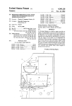
FIG. 1 is a schematic block diagram of an apparatus
more, these machines are fairly singular in their use,
for duplicating a signature according to the present
thereby requiring a relatively large capital expenditure
invention;
for a singular use. Other disadvantages include the diffi
FIG. 2 is a top plan view of a digitizer pad depicting
culty in providing, on the one hand, security and, on the
other hand, easy accessibility by authorized persons and $5 the layout of the pad for use with a computer program
according to the present invention including the layout
easy reproduction of any one of a plurality of signatures
of an input keyboard;
or handwritten messages.
FIGS. 3A, 3B and 3C are photoduplications of three
SUMMARY OF THE INVENTION
signatures, FIG. 3A being a duplication of the actual
The present invention provides a method and appara 60 signature as written by D. L. Hardin, FIG. 38 being a
replication of the signature of FIG. 3A by an embodi
tus for replicating a handwritten word at a determinable
ment of the present invention in which the greatest
location on a piece of paper. Such a word can include a
amount of smoothing was utilized, and Fig. 3C being a
person’s signature as well as a handwritten note by that
replication of the signature of FIG. 3A in which there
person. The present invention utilizes a computer con
has been no smoothing; FIG. 3D is an enlarged portion
nected to a means for providing a plurality of coordi
of FIG. 3C; and FIG. 3E is an enlarged portion of FIG.
nate points that together represent the handwritten
3D, both used to illustrate the smoothing algorithm
word. In a preferred embodiment, the computer re?nes
the raw data received from the coordinate producing
utilized by the present invention;
3
4,817,034
a computer program according to the present invention;
FIGS. 5, 6 and 7 are a schematic flow chart of the
program routine used to replicate a signature;
FIGS. 8, 8A and 8B, collectively, and FIGS. 9 and 10
are schematic flow charts of the signature recording
ning system to determine the horizontal and vertical
positions.
program routine;
The DIGI-PAD digitizer pad also produces two
positive signals that are indicative of the relative loca
tion of cursor 22 with respect to the surface of pad 20.
The pad produces a "one" together with location infor
mation when cursor 22 is in contact with digitizer pad
20 and produces a “zero” together with location infor
FIG. 11 is a schematic ?ow chart of the program
routine for displaying the log of the history of a particu
lar signature ?le;
FIG. 12 is a schematic flow chart of the program
routine that erases a signature file;
DETAILED DESCRIPTION OF THE
PREFERRED EMBODIMENT
mation when cursor 22 is located proximate to the sur
15 face of digitizer pad, but not in contact therewith. In a
preferred embodiment of the present invention, the
With reference now to the ?gures in which like nu
contact indication is provided by a switch located in
cursor 22, which switch is activated by pressing cursor
merals represent like elements throughout the several
views, and in particular with reference to FIG. 1, a
computerized hardware duplication system 10 is de
picted. System 10 is based on a general, programmable
digital microcomputer 12. Microcomputer 12 can be
4
nected to the cursor coil senses the phase reversal that
occurs when the current signal sweeps past. The con
tents of the counter then contains a number that is pre
cisely related to the cursor position on the cursor pad.
The digitizer pad also contains a Cartesian X-Y scan
FIG. 4 is a schematic ?ow chart of the main menu of
20
22 against the surface of digitizer pad 20. A third type of
indication is also possible from digitizer pad 20 when
cursor 22 is not located proximate to the surface of
any one of a number of commercially available mi
digitizer pad 20. This indication is simply the transmis
crocomputers, such as an IBM PC brand computer or a
sion of no location information. If microcomputer 12
compatible thereto. Microcomputer I2 is bidirection
were receiving information from digitizer pad 20 start
ally, electrically connected to a RAM buffer 14 and a
ing at a timed pulse and no information were received
until a known time interval later, then this lack of re
ceived information would be indicative of cursor 22
program memory 16 which can be a ROM. Alterna
tively, program memory 16 can be a ?oppy disc or hard
disc, and then when the program is needed it can be
transferred to the directly accessible RAM memory of
being not proximate to the surface of digitizer pad 20.
For the DIGI-PAD 5 digitizer pad, the proximate lock
microcomputer 12. Microcomputer 12 also includes
height is one inch. Such a pad has a maximum scan rate
off-line memory such as disc memory 18. Disc memory
18 can be either a hard disc or a ?oppy disc driven by
of 200 X and Y points per second with a resolution and
repeatability of 0.001 inches.
appropriate mechanical drives.
Input is provided to microcomputer 12 through a
digitizer pad 20 and stylus or cursor 22. An operating
Digi-Pad 5 digitizer pad was con?gured to provide 200
coordinate pairs of continuous information per second
embodiment of the present invention used a commer
at a Band rate of 9600 with parity disabled and using an
To “write” the signatures in FIGS. 3B and C, the
eight bit character in the serial Input/Output RS232
cially available digitizer pad manufactured by the
GTCO Corporation of Rockville, Md. The signatures
mode. It was also con?gured to include a pushbutton
code with space and carriage return, but no line feed,
reproduced as FIGS. 38 and 3C were produced by
GTCO digitizer pad Model DIGl-PAD 5. This digi 40 with a ?ve digit ASCII, high resolution packed binary
character of inch data being transmitted.
tizer pad is fully described in the DIGI-PAD User’s
With reference to FIG. 2, the top surface of digitizer
Manual Serial Number 21A7lD4, Revision E dated
pad 20 is depicted. Digitizer pad 20 is utilized not only
Feb. 29, 1984.
for recording a signature or other written note, but also
The DIGI-PAD digitizer pad 20 operates on an elec
tromagnetic principle based upon measuring the time
for an electromagnetic signal to travel down an axis.
The wave front is generated by a rapidly switched cur
rent signal in a matrix of conducting wires embedded in
a rigid tablet. The electromagnetic wave is used to
produce an absolute coordinate system of information.
The DIGI-PAD system also includes a stylus or cursor
having an inductance coil which is operable at high
signal switching levels. The DIGI-PAD digitizer pad
utilizes a complex signal that is induced in the cursor
coil by an electromagnetic ?eld created by the sequen
tially pulsed current applied to consecutive tablet ma
trix wires. This system provides a means for measuring
the cursor position relative to an aribitrary reference
point or orgin on the tablet (which for Digi-Pad 5 is
located in the lower left hand corner as seen in FIG. 2)
as a result of the linear relationship between the distance
and time the current signal arrives as sensed by the
cursor coil. The electronics provided with the digitizer
pad, which is disclosed in greater detail in the aforemen
45
for providing input commands to microcomputer 12.
Digitizer pad 20 includes a paper location area 24 out
lined by a perimeter border 26. Area 24 in the presently
preferred embodiment is 85 inches by 11 inches so that
a standard sheet of paper can be accurately located.
Located inside border 26 is a signature rectangle 28
having a signature line 30, the beginning of which is
marked with an “X” 31. By de?ning the location for
placing the signature, a more simpli?ed computer pro
gram, described below and disclosed in the microfiche
appendix, can be used with digitizer pad 20, to accu
rately locate the signature when it is being recorded and
to cause it to be accurately reproduced at a different,
and usually lower, location on paper. This simpli?ca
tion results from the use of a constant offset from “X”
31 to a point that is indicated in area 24 by an operator
using cursor 22, as described in greater detail hereinbe
low.
Digitizer pad 20 also has a keyboard area 32 which
contains three types of indicia: alphabet, numbers, and
tioned user’s manual, utilizes a precision clock source 65 commands. The alphabet indicia are located in the
upper portion of keyboard area 22 and each letter of the
set to a digital counter at the moment the electromag
alphabet is located in its own square, such as alphabet
netic signal passes the tablet reference point. The count
square 34 for the letter “A”. The numbers of keyboard
in the clock is frozen when the detection circuitry con
5
4,817,034
.l‘i
area 32 are located in a midportion thereof with each
number being in its own numerical square, such as nu
6
paper, thereby preventing slippage while plotting. The
merical square 36 for the number “9”. Keyboard 32 is
also provided with four commands, three of which are
located in the lower portion thereof. These are the
“yes” command box 38, the “no” command box 40 and
plotter can be manually fed, one sheet at a time, or can
be coupled to a paper feeder.
In the embodiment depicted in FIG. 1, plotter 48 is
coupled to an automatic paper feeder physically
mounted on top of plotter 48 and feeds one sheet of
paper at a time. Paper feeder 50 receives software com
the “rese ” command box 42. However, for ease of use,
a forth command box 44 for the command “enter" is
located between alphabet squares 34 and numerical
squares 36.
l
their periphery'which make small indentations in the
10
mands from microcomputer 12 and provides status sig
nals back to microcomputer 12. Similarly, plotter 48
Althought the operation of keyboard area 32 is de
receives its programming commands and data com
scribed in greater detail hereinbelow, for ease of under
mands from microcomputer 12 and returns status com
standing the present invention the use of keyboard area
mands to microcomputer 12.
32 will be described now. As mentioned above, when
With reference now to FIGS. 4 through 12, and also
cursor 22 is placed anywhere within the active area of 1S to the appendix, the computer program which operates
pad 20 and in proximity to the surface thereof, the coor
system 10 will now be described. Initially, it is noted
dinates of the location of the tip of cursor 22 is provided
that the computer program is written in Microsoft basic
by the counter of the electronics of pad 20 when cursor
to be run under the MSDOS operating system. With
22 senses the travelling current pulses. Thus, it should
respect to FIG. 4, a main menu selection routine 80 is
be obvious to those skilled in the art that, for example, 20 depicted. When the computer is powered up, an autoex
the letter “A" can be provided to the computer simply
ec.bat program (not shown) in the DOS operating sys
by placing cursor 22 over the area defined by “A” and
tem causes computer 12 to load main menu routine 80
then using software to decode the received position
into program memory 16. The main program begins in
information of cursor 22 with the known position of the
process box 82 where an introductory message is dis
“A” square 34.
25
Returning to FIG. 1, computerized handwriting du
plication system 10 further comprises two output de
played on video monitor 46 (see Appendix, beginning at
line 240). The screen of video monitor 46 is then
blanked and a message of “Good morning, afternoon or
vices, a video monitor 46 and an X-Y plotter 48. Video
evening”, as the case may be, is displayed together with
monitor 46 is a standard, commercially available video
the message "Do you want to use a previously recorded
monitor together with a video board located in mi 30 signature‘l; (yes/no)”. The program then proceeds to
crocomputer 12. In the present embodiment of the in
decision box 100 while the program awaits an answer
vention, video monitor can simply be an alphanumeric
from the operator.
monitor and need not be a color or graphics quality
The operation of the choice selection and entry will
monitor.
now be described. As soon as an entry is made by touch
Plotter 48 is a conventional, commercially available 35 ing cursor 22 to the appropriate command box 38, 40 or
X-Y plotter, such as Model 595 manufactured by Hous
42 (FIG. 2). The program branches to subroutine 5200
ton Instrument, Inc. of Austin, Tex., and described in
(see program listing) where the keyboard entry is de
their publication entitled “PC Series Digital Plotter
noted “CHOICES” and the program calls subroutine at
Operation Manual” No. M14050 (1984). For the pur
line 12470 of the program listing. This subroutine re
pose of describing the presently preferred embodiment
turns the selected key pad item and ?rst initializes the
of the present invention, the Houston Instruments plot
possible variables. When the digitizer pad 20 is touched,
ter will be described. This plotter is a small, rugged
an interrupt is sent to the program and the program
branches to a third nested subroutine at program line
plotter designed for use with personal computers, such
as the IBM PC computer. The plotter uses the Houston
Instrument Digital Microprocessor Plotting Language
12400 (because the GTCO digitizer pad is being used).
45
(DM/PL) for operation with the microcomputer. Such
plotter is a tabletop unit with all electronic circuitry
provided. The plots can be produced on standard sized
paper (85 by 11 inches) by moving the plotting paper
vertically in and out and moving the drawing pen trans
versely back and forth to produce the desired plot. The
plotter receives its operating instructions from the mi
crocomputer using standard RS-232C signals. The
Model 595 plotter also has a provision for using and
selecting one of four different pens. This is done by 55
At this subroutine, the point touched on digitizer pad 20
is called XY$ by the statement:
XYS = inputS(13,# l).
The program then converts data to inches with the
command:
YD=0.001
*VAL(MID$)XY$,8,5)).
The program executes a coordinate transform to con
vert the absolute value received to the overlay orienta
tion as depicted in FIG. 2. For the present example, this
is simply the program line:
mounting the four pens on a rotatable housing that can
be controlled by the host computer. The plotter has a
The point touched on the digitizer pad has now been
buffer of 256 bites and utilizes 7 data bits with a select
able one parity bit and two stop bits. The model 595
converted to inches and transformed to the proper X-Y
coordinate system. The program checks beginning with
plotter used to replicate signatures in FIGS. 33 and C 60 program line 12500 whether the point coordinates that
was con?gured with a 9600 baud rate for data with no
have been provided by cursor 22 touching digitizer pad
parity and bit number 8 to set to a 1. In performance, it
20 are within the limits of the key pad area. Depending
has a maximum speed of 3 inches per second in the axial
upon which one of a series of IF THEN tests are true,
direction and 4.2 inches per second in the diagonal
the appropriate subroutine is called. Since presumably a
direction, and has an addressable resolution of 0.001 65 command box has been touched, the program will
inches, 0.005 inches, 0.1 mm, or 0.025 mm. The plotter
branch to program line 12710 where the program con
has grit wheels and pinch wheels for grasping the paper
verts the entered point into a position within the appro
while plotting. The grit wheels have small particles on
priate function area and where entries falling near the
7
4,817,034
boundary lines are eliminated. The program lines for
requested signature is present. If the requested signature
making these calculations are as follows:
is not present, the program branches to process box 112
where the program causes video monitor 46 to display
the message “insert proper disc and touch ‘yes’ when
okay", and then branches back to the top of process box
104.
If the signature is present and the operator enters the
raponse “yes” by touching cursor 22 to command box
38, the program will continue to process box 114. In
process box 114 the program requests the entry of the
IF YC<0.04 or YC>0.96 OR XC<0.05 OR
XC>O.95 THEN RETURN FUNC=CINT(X-7)
IF FUNC=1 THEN CHOICE$=“YES": GOTO
12810
IF FUNC=2 THEN CI-IOICES=“NO"; GOTO
12810
IF FUNC=3 THEN CHOICE$=“RESET”:
GOTO 12810
The ?rst two lines check that the point is not within 0.05
inches of the line. The next line rounds the input point
security code corresponding to the signature identi?ca
tion. However, the operator can also select the “reset”
command box, whereupon the program branches back
to an integer and then substracts 7 from it and the re
through off page connector 84 to FIG. 4. As with the
mainder will either be a 1, representing the choice of
“yes", a 2 representing the choice of “no" or a 3 repre
senting the choice of “reset". The function has now
an error is made, can restart the security code by touch
ing "NO" command box 40. Also as with the entry of
selection of the signature identi?cation, the operator, if
been selected and it is printed on the screen of monitor
46 and the program responds appropriately.
Hence, referring again to FIG. 4, if the yes selection
20
the signature identi?cation, the selection of the appro
priate alphanumeric square will result in the selection
being displayed on video monitor 46. The process will
continue until the “enter” command box 44 is touched.
is touched by the operator, as shown in decision box 100
When the enter command box 44 is touched, the
the program branches through an off page connector
program will branch to decision box 116 whereupon the
102 to FIG. 5. If the no selection is touched, the pro
program will check the security code. If the code is
gram proceeds to a decision box 200. Finally, if the reset
command box 42 is touched, the program branches back 25 incorrect, the program will index a counter so that no
more than three tries or guesses at the security code can
to the top of decision box 100.
be attempted. The program does this in decision box 118
Assuming that the operator selected the “yes" option
and if the number of tries is greater than or equal to
to the question of whether a previous signature is to be
three, the program branches back to FIG. 4 through off
used, the program branches to the “USE” routine and
enters process box 104. In process box 104, the program 30 page connector 84. If the number of tries is less than
three, the program branches back to the top of process
displays all of the signatures which are presently stored
box 114 where the operator is again asked to enter the
on the ?oppy disc in the default disc drive of micro~
security code. Assuming the security code is correct,
processor 12, indicated as disc memory 18. In decision
the program continues to process box 120 where the
box 106, the program ascertains from the operator
programs asks the number of signatures which the oper
whether the desired signature is on the ?le. At this
ator wishes to have written. Again, the operator is
point, the operator can select reset, in which case the
given the opportunity to change his or her mind by
program branches through off page connector 84 back
selecting the “no" command box 40, in which case the
to the main menu routine 80 of FIG. 4. If the operator
program branches back to the top of process box 120.
positions cursor 22 on NO command box 40, the pro
gram branches through off page connector 107 back to 40 Alternatively, the operator can touch the “reset" com
mand box 42 whereupon the program branches back to
FIG. 4 and into decision diamond 200 where the main
FIG. 4 through off page connector 84.
menu asks whether the operator wishes to record a new
As described above, the program will decode the
signature. Assuming that the operator selects the
selected number depending upon which numerical
“YES” command box 38 with cursor 22, the program
then enters process box 108 where the program causes 45 square 36 cursor 22 touches. If the wrong square is
touched, (e.g. alphabet square 34) the program indicates
the screen of video monitor 46 to display a request for
an error and again asks for the number of signatures to
the entry of the identi?cation of the desired signature.
be written. The selected numbers are displayed on
The signature ?le identification is provided by the oper
video monitor 46 and the program continues as soon as
ator touching the appropriate alphabet square 34 or
the “enter” command box 44 is touched. The program
numerical square 36. On the other hand, the operator
can also select reset command box 42 in which case the
then determines in decision box 122 whether one or
program immediately branches back to FIG. 4 through
greater than one signatures have been selected and the
program branches respectively through off page con
nector 124 and 126 to the appropriate routine depicted
in FIG. 6 or FIG. 7.
off page connector 84, or can select the “NO" com
mand box 40 in which case the program branches back
to the top of process box 108. When the operator selects
the appropriate alphanumeric square, the program uses
a similar locating subroutine as described above with
respect to the command boxes 38, 40 and 42.
To summarize, the program ?rst makes an in-bounds
check and then uses a similar mathematical algorithm to
check for the particular alphanumeric square that has
If the operator selects just one signature to be repli
cated, then the program continues through off page
connector 124 to FIG. 6 where the software in process
box 128 asks the operator to place the cursor 22 on
digitizer pad 20 at the location where the signature is to
be replicated. The operator is also given the choice to
touch “reset,” whereupon the program branches
been touched. Once the selection has been decoded, the
through off. page connector 84 to the main menu de
selection is displayed on video monitor 46. The pro
picted in FIG. 4. As soon as the operator touches digi
gram waits until another alphanumeric box is selected,
thereby repeating the foregoing process, or until the 65 tizer pad 20 with cursor 22, the program calculates
where the signature is to be placed and then enters
enter command box 44 is selected. Once the enter com
decision box 130 where a determination is made
mand box 44 is selected, the program continues to deci
whether the entire signature will be within the bound
sion box 110 where the program checks whether the
9
4,817,034
ary capabilities of plotter 48 (FIG. 1). If the program
calculates that the signature will not be within proper
bounds, then the program branches to decision box 132
where the operator is asked whether the signature
should be used anyways. If the operator touches the
“rese ” command box 42, the program branches back to
the main menu through off page connctor 84. Alterna
10
connector 126 to FIG. 7. The program proceeds
through the same initial steps beginning with process
box 128 and continuing through process box 140 as
described above'with respect to FIG. 6 for a single
signature replication. However, from process box 140,
as shown in FIG. 7, the program proceeds to decision
box 152 where the computer keeps track of the number
tively, if the operator selects “no” command box 40,
of signatures that have been printed. If the number of
signatures which has been completed is not equal to the
box 128 where the procedure is repeated. If the pro 10 number indicated by the operator in decision box 122,
gram determines in decision box 130 that the signature
FIG. 5, the program branches back to the top of process
is within the boundary limits, or if the operator indicates
box 134. As the program controls plotter 48 to write the
to use the signature anyway, the program proceeds to
signatures on a plurality of sheets, the operator is kept
then the program branches back to the top of process
process box 134 where paper feeder 50 is commanded to
feed a sheet of paper to plotter 48. The program then
proceeds to decision box 136 where the program deter
mines whether there is a print ready command from the
plotter 48. Typically, plotter 48 provides such a com
mand by using a hardwired handshanking signal con
nected to microcomputer 12 as an input signal.
If the program determines in decision box 136 that
plotter 48 is not ready, the program branches to process
box 138 where the program runs the "not ready” rou
apprised of the progress by the message “Printing #_
of _; touch reset to terminal” being displayed on video
monitor 46. Thus, the program indicates not only the
number of pages to be printed, but also the current page
which is being printed. As in the subroutine for the
single signature replication, the operator can terminate
the job at any time simply by touching reset command
box 42 with cursor 22. The program poles digitizer pad
20 upon completion of each signed sheet. If it detects
that the reset command box has been touched, the pro
tine. This routine noti?es the operator by displaying a
gram branches to decision box 154 where the following
message on video monitor 46 that the plotter is not 25 message is indicated:
ready and that the operator should attend to the error
job temrinated at number _. of _
condition. The program then branches back to the top
touch yes to resume current signature
of process box 134 where the program waits until it
touch reset to start another job.
receives an indication that the paper has been properly
fed. If the program determines in decision box 136 that 30 Thus, if the operator touches yes command box 38, the
program branches back to the top of process box 134. If
plotter 48 is ready, the program proceeds to process box
either the no or reset command boxes 40 or 42 are
140 where the program instructs plotter 48 to feed the
touched, the program branches to decision box 156
paper and commence printing the signature at the loca
where the program asks the operator to indicate
tion indicated by the operator in process box 128. It is
whether the current signature should be reused or
noted that the paper which is fed is usually a typed
whether another job is to be started. If the operator
letter that simply needs a signature or handwritten post
touches reset command box 42, the program branches
script before it can be sent.
through off page connector 84 back to the main menu in
The program proceeds from process box 140 into a
FIG. 4. On the other hand, if the operator indicates that
timing loop 142 whereupon if no interruption is indi
cated the program branches back to the top of process 40 the current signature is to be reused, the program
branches back through off page connector 150 to the
box 128 through on page connector 144. On the other
top
of process box 120 in FIG. 5.
hand, while the signature is being printed, video moni
Returning again to FIG. 4, as mentioned above, the
tor 46 displays a message instructing the operator that
program asks the operator in decision box 200 whether
the process can be halted by touching “reset” command
box 42. Should the operator thus respond, the program 45 a new signature is to be recorded. If that is the case, a
program branches through off page connector 202 to
is interrupted and proceeds to process box 146 where
FIG. 8 where the program enters the signature record
the program halts and displays a message to the opera
ing routine, and in particular a capture subroutine 204,
tor on video monitor 46 to indicate by touching “reset”
which is depicted in FIG. 8A.
command box 44 if the operation is to be terminated or
Subroutine 204 begins in process box 206 where the
the “yes” command box 38 if the single signature mode
program ?rst initializes digitizer pad 20, sets up ram
is to be rerun. If the operator touches the “yes" com
buffer 14, and prepares the system to commence accept
mand box 38, the program branches through on page
ing a large number of data points at the rate of 200
connector 144 back to process box 128. On the other
points per second. Then, the program gives the opera
hand, if the operator touches “reset" command box 42,
the program branches to decision box 148 where the 55 tor a start tone and begins to receive data. As mentioned
above, the computer will receive data from the digitizer
operator is asked whether the same signature is to be
from the commencement of the start tone. If cursor 22
reused. If the operator touches “reset" command box
42, the program branches through off page connector
is not located proximate to the surface of digitizer pad
20 (about an inch above the top thereof), then no data
other hand, if the operator touches the yes command 60 will be sent to the computer and effectively only zeros
will be stored. When cursor 22 is located proximate to
box 38, then the program branches back through off
84 back to the main menu routine of FIG. 4. On the
digitizer pad 20, but is not pressing on the pad, digitizer
page connector 150 to the use routine depicted in FIG.
pad 20 will give a “pen down” signal. When cursor 22
5 at the top of process box 120, where the operator is
is pressing down on digitizer pad 20, a switch is thrown
again asked to enter the number of signatures to be
written.
65 therein and a “pen down” signal is produced by digi
tizer pad 20. Thus, from process box 206 the program
If in decision box 122, FIG. 5, the program deter
proceeds to a decision box 208 where the program
mines that the operator has requested more than one,
awaits the receipt of a “pen up" or a “pen down” signal.
signature, then the program branches through off page
11
4,817,034
If neither signals are present, the program will branch
12
program, the program proceeds to subroutine box 222
to process box 210 and will load a zero in buffer 14.
where the program processes the data and tests the data
After a time delay (of about 0.005 second), the program
further. The re?ne subroutine is depicted in greater
detail in FIG. 8b. First, the subroutine proceeds to pro
cess box 224 where the program compacts the data by
deleting all coordinates that have a leading zero. Then
branches back to the top of decision box 208. As soon as
digitizer pad 20 indicates that cursor 22 is proximate
thereto, the program determines in decision box 208
whether a “pen up” or a “pen down” signal has been
received. If a "pen up” signal has been received, the
program in process box 212 prefaces the X-Y coordi
nate received from digitizer pad 20 with a zero, then in
process box 214 stores the number in buffer memory 14.
The program then proceeds to decision box 216 where
the program again determines whether cursor 22 is not
proximate to digitizer pad 20. As long as cursor 22 is
proximate to but not touching digitizer pad 20, the pro
the subroutine calls a nested subroutine in subroutine
box 226 for smoothing the compacted data. The
smoothing subroutine is described in greater detail here
inbelow with respect to FIG. 3. Smoothing subroutine
226 also changes the data from absolute to relative and
further inserts the computer commands necessary to
operate plotter 48. From subroutine box 226, the pro
gram stores the re?ned data to disc in storage box 228.
An example of re?ned data obtained from the raw data
listed in appendix 1 is shown in appendix 2, and is ex
gram continues to loop to the top of decision box 208.
plained in greater detail hereinbelow. From storage box
When the program receives a “pen down” signal, it
228, the program proceeds to terminal 230 where the
branches to a process box 216 where it prefaces the X-Y
program returns to the main subroutine depicted in
coordinate received from digitizer pad 20 with a “1".
The program then proceeds as described above by stor 20 FIG. 8 and enters decision box 232.
The program in decision box 232 asks the operator
ing the received number in buffer memory 14, and de
whether the signature should be accepted or not. If the
termining whether cursor 22 is not proximate to digi
operator touches the yes command box 38, the program
tizer pad 20 in decision box 216.
proceeds to decision box 234 where the program asks
Thus, it can be seen that in the process of a person
the operator whether the operator desires a sample plot
signing his or her signature, initially a number of zeros
or not. If the data is not acceptable, the program
will preceed the raw data received from digitizer pad
branches to decision box 236 where the program asks
20. Then, a number of coordinates preceeded by a “0”
the operator whether the signature is to be redone. If
will be stored, and ?nally, a number of coordinates
the operator indicates yes, then the program branches
preceeded by a “1" will be stored. As the signature is
being written, the pen may be lifted from the surface of 30 back to the top of subroutine box 204. If the operator
digitizer pad 20, such as to begin a new word or to clot
an “i.” At that time, cursor 22 still remains proximate to
touches no or reset command boxes 40 or 42, the pro
gram branches back through off page connector 84 to
the main menu routine of FIG. 4. If when the program
digitizer pad 20, but the pen down signal is no longer
is in decision box 234, the operator indicates that no
received. Therefore, the digitizer pad still produces an
X-Y coordinate, but the program through decision box 35 sample plot is desired, the program also branches back
with a “0.” As soon as cursor 22 is again placed into
to the main menu routine of FIG. 4 through off page
connector 84.
contact with digitizer pad 20, the pen down signal will
If the operator responds that a sample plot is desired,
208 in process box 212 will preceed the coordinates
the program then proceeds through a series of steps
be received and the coordinates will be preceded by a
“1.” When the signer is done with the signature or other 40 similar to steps in process boxes 134 through 140 of
FIG. 6. Therefore, from decision box 234, the program
handwritten message, cursor 22 is lifted away from
proceeds to process box 238 where the paper is prefed
being proximate to digitizer pad 20 and the program
from paper feeder 50 to plotter 48 (FIG. 1), the program
determines in decision box 216 that the cursor is no
waits in decision box 240 until the paper is ready, and
longer proximate to the surface of digitizer pad 20. At
this point, the program returns through terminal 217 to 45 then in process box 242 the program commands plotter
48 to feed and print the paper. From process box 242 the
the record routine depicted in FIG. 8.
program proceeds to a decision box 244 where the oper
An example of such raw data is depicted in appendix
ator is asked whether the sample signature is to be saved
1. This data represents the signature written in FIG. 3a.
or not. The operator has three choices. If the operator
When the program returns to the record routine in
touches reset command box 42, the program returns to
Fig. 8, it enters a decision box 218 to determine whether
the main menu routine of FIG. 4 through offpage con
the recording is complete. When the recording is com
nector 84. If the operator touches the yes command box
plete, the program branches to decision box 220 where
38, the program branches through off page connector
the program determines whether to accept the data or
246 to a continuation of the recording routine depicted
not. Basically, the program simply checlm all of the data
in FIG. 9. If the operator touches the no command box
received to make sure that it is in the correct format.
40, the program branches through off page connector
The expected format is blocks of 12 digits where the
248 to a reprocess subroutine depicted in FIG. 10.
?rst digit of the block is a zero or one, the next ?ve
Continuing the recording routine in FIG. 9, the pro
digits are the absolute position in ten thousandths of an
gram enters input box 250 where the operator is asked
inch in the X direction, then a space, then five digits to
indicate in tens of thousandths of an inch the absolute 60 to supply the identi?cation for the desired signature.
The operator can supply a signature identi?cation of
position in the Y direction. If the data is unacceptable,
either letters or numbers by touching the appropriate
the program provides that message on video monitor 46
alphanumeric squares 34 or 36 on digitizer pad 20.
that the operator should either touch reset command
These letters and numbers are decoded as described
box 42 or the no command box 40 depending upon
whether the operator desires to return to the main menu 65 hereinabove. Alternatively, the operator can touch
reset command box 42 if a particular signature identi?
depicted in FIG. 4 or whether the operator wishes to
cation is not wanted and the program branches back to
try again and record another signature. If the data was
the top of input box 250. As the operator selects each
received in the correct format and is acceptable to the
13
4,8 17,034
letter or number, it is displayed on video monitor 46.
When the operator is satis?ed with the signature identi
?cation, the operator touches the enter command box
14
Returning
:iagain to the main menu routine in
FIG. 4, if the operator when asked whether to record a
new signature in decision box 200 touches the no com
mand box 40, the program proceeds to decision box 300.
In decision box 300, the program asks the operator
whether a review of the signature log is desired. The
identi?cation has been previously used. If the identi?ca
program keeps track of all uses of a particular signature
tion has been previously used, the program branches to
file, the particular user and the date and time of use to
process box 254 where the message “Identi?cation al
provide desirable accounting information to the opera
ready used" is printed on video monitor 46. From pro
cess box 254, the program branches back to the top of IO tor. The purpose of the log routine 300 is to provide the
information that has been kept to the operator. As with
input box 250. If the identi?cation has not been previ
decision boxes 100 and 200, the operator can select
ously used, then the program proceeds to input box 256
“reset", “yes”, or “no”. If the operator selects "yes”,
where the operator is asked to supply a security code.
the program branches through oi'fpage connector 302 to
As with the signature identi?cation, the operator can
42 and the program proceeds to decision box 252. In
decision box 252, the program determines whether the
touch the no or reset command boxes 40 or 42 to reject
a selected entry and the program will return to the top
of input box 256. When the operator is satis?ed with the
selected security code, the enter command box 44 is
touched and the program proceeds to decision box 458
decision box 304 (FIG. 11).
In decision box 304, the program instructs the opera
tor to supply the identi?cation of the signature ?le that
is desired. As with other selection procedures, decision
box 304 requires the operator to supply the name of the
where the program veri?es whether the selected secu 20 signature identi?cation by touching the appropriate one
or ones of the alphanumeric square 34 and 36. The
rity code is proper or not by checking to see if it con
tains only acceptable values and is of the correct length,
and by asking the operator to enter the security code
and then comparing this later entered code with the ?rst
selected square is displayed on video monitor 46 (FIG.
1). If the operator makes a mistake or desires a different
identi?cation number, he or she touches the no com
selected code. If the code is not proper, the operator is 25 mand box 40, and the program branches back to the top
of decision box 304. The operator also has the option of
asked whether to abort or to reenter the signature iden
returning to the main menu routine depicted in FIG. 4
ti?cation and security code. If the operator responds by
by touching reset command box 42, whereupon the
touching the no command box 40, the program
program branches through off page connector 84 back
branches back to the beginning of input box 250. If the
reset command box 42 is touched, the program 30 to the top of decision box 100 in FIG. 4.
branches back to the main menu routine through off
page connector 84. If the operator veri?es the code and
reenters the same code as previously selected, the pro
As soon as the operator has selected the identification
of the signature ?le and has touched the enter command
box 44, the program branches to decision box 304. In
decision box 304, the system checks to see that the
gram proceeds to process box 260 where the signature
identi?cation and security code are stored on disc mem 35 signature is on ?le. If the signature is not on ?le, the
operator is prompted by a message displayed on video
ory 18 (FIG. 1). After saving the signature identi?ca
monitor 46 to install a new diskette. If the signature
tion and code, the program proceeds back to the main
identi?cation identi?es a signature that is on ?le, the
menu routine through off page connector 84.
system proceeds to process box 308 where the log infor
With reference now to FIG. 10, the program pro
ceeds through offpage connector 248 from FIG. 8 if the 40 mation is caused to be displayed on video monitor 46.
When the operator is ?nished with the display, he or she
operator indicates that the signature is not to be saved.
can touch yes, no, or reset command boxes 38, 40 or 42
The program enters decision box 260 and asks the oper
to return the system back to the main menu routine
ator whether to reprocess the signature. It is noted, as
depicted in FIG. 4 through offpage connector 84.
described hereinbelow, that the operator can select the
Returning to FIG. 4, if the operator touches the no
reprocessing level. This can be done at this time and is
described in greater detail hereinbelow.
command box 40 when the program box is in decision
box 300, the program branches to decision box 400. In
If the operator indicates to reprocess the signature,
decision box 400, the program prompts the operator by
then the program proceeds to process box 262 where
displaying a message on video monitor 46 asking if the
the operator is requested to select the smoothing level
desired. This procedure is also described hereinbelow. 50 operator desires to erase a signature. If the operator
As soon as the operator selects the smoothing level by
touches yes command box 38, the program branches
through offpage connector 402 to decision box 404 in
touching the appropriate numerical square 36, and then
FIG. 12. Alternatively, the operator can touch reset
touches the enter command box 44, the program
command box or no command box 42 or 40, whereupon
branches back to the recording routine of FIG. 8
the system returns back to the beginning of decision box
through offpage connector 264 and the data is repro
100.
cessed in subroutine box 222 and the subsequent steps
repeated.
In decision box 404 of the erase routine, the program
displays the signatures on the diskette and asks the oper
If the operator selects not to reprocess the data, the
ator by printing a message on video monitor 46 whether
program branches to decision box 266 where the opera
the signature sought to be erased is on ?le. If the opera
tor is asked whether another signature is to be recorded.
tor touches no or reset command boxes 40 or 42, the
If the operator touches the yes command box 38, then
system branches back through offpage connector 84 to
the program branches back to the top of the recording
the main menu routine in FIG. 4. If the operator
routine (beginning in FIG. 8) through offpage connec
touches the yes command box 38, the system branches
tor 202. On the other hand, if the operator touches the
reset command box 42 when asked by the program 65 to process box 406 where the operator is instructed to
enter the identi?cation code of the signature on ?le. As
when in decision box 260 or 266, then the program
branches back to the main menu routine depicted in
the operator selects the appropriate alphanumeric
FIG. 4 through offpage connector 84.
squares 34 and 36, the selected choice is displayed on
15
4,817,034
video monitor 46. If the operator makes an error, the
operator can touch the no command box 40 and the
program will return to the top of process box 406.
When the operator touches the enter command box 44,
the program branches to decision box 408. In decision
box 408, the program ascertains whether the ?le for the
requested signature identi?cation code is present on the
installed diskette. If the file is not present, the program
branches to process box 410 whereupon the message
“Signature not present” is printed on video monitor 46,
and the program branches to the top of decision box
16
columns E and F in row 7. Thus, the absolute position
from the origin of digitizer pad 20, which is in the lower
left hand corner thereof, is X=2.976 inches, Y=9.37
inches. This point was generated at location 502 in the
signature of FIG. 3A. It can also be seen that the X
coordinate in column B is preceded by the number “1”
indicating that the “pen down” signal has been received
by microcomputer 12. Every ?ve thousandths of a sec
ond, digitizer pad 20 sent the coordinates of a point. As
can be seen from FIG. 3A, the signers pen moved
downwardly toward the bottom left hand corner of
404. If the requested signature ?le is present, the pro
gram proceeds to process box 412. In process box 412,
the program requests the operator to verify that the
selected signature ?le is in fact to be erased by display
digitizer pad 20. Thus it can be expected that both the X
subroutine 222 (FIG. 8B) of the recording routine, the
present invention also involves re?ning the received
signature. The re?ned subroutine 22 involves not only
compacting data but also smoothing the signature in
25 can be seen that the signers pen did not leave the paper
accordance with a preselected, variable amount of
ing function will now be described with reference being
had to FIGS. 3A through 3E and Appendices 1 and 2.
ceived in rows 48 and 49 are probably the result of the
signers simply not bearing down on the pen. In any
case, they are aberations in the overall signature. It can
be noticed that there is a distance between the absolute
As mentioned above, digitizer pad 20 sends 200 points
positions of the point coordinates located before and
and the Y coordinates should decrease. This can be seen
in the next coordinate point listed in columns G and H
of row 7 whereby the absolute value of the X position
changed by two thousandths of an inch toward the left
ing an appropriate message on video monitor 46. If the
hand side, but the Y position did not change at all. Since
operator touches the no or reset command boxes 40 or
each point is sent every ?ve thousandths of a second,
42, the program branches back to the main menu rou
the space between points will simply be a function of
tine through offpage connector 84. If the operator
touches the yes command box 38, the program proceeds 20 the time it takes the signer to move the pen over digi
tizer pad 20. In row 46,. columns G and H, it can be seen
to process box 414. In process box 414, the program
that for one hundredths of a second the computer re
erases the identi?ed signature ?le and then returns to
ceived a pen up signal because the X coordinate is pre
the main menu routine through offpage connector 84.
ceded by a "0”. Based on a review of the signature, it
As mentioned above with respect to nested re?ne
smoothing. The algorithm for performing the smooth
except to place a dot above the i, the dot being denoted
by numeral 504. It is believed that the pen up signal
received in row 46, as well as the pen up signals re
after the groups of “pen up” coordinates. This is one
disregarded all points generated when cursor 22 was 35 reason why the signatures should be smoothed with a
smoothing program. A further observation is that dot
not touching the top of digitizer pad 20 and “compact
504 in FIG. 3A can be seen in the raw data in Appendix
ing” the remaining points, the program performs a
A in the entire row 56. This means that it took six data
smoothing function on the remaining points Basically,
points or three hundredths of a second for the signer to
the computer compares all the remaining points in sets
of three, beginning with the ?rst point generated, and 40 dot the “i” of the signature. It should also be observed
that the coordinates of the dot are substantially the
then proceeding in the direction of the drawn line. FIG.
same, thereby con?rming that these data points do in
3A shows a signature of D1... Hardin as actually written
deed designate dot 504.
on digitizer pad 20 while the recording routine was
The operation of the smoothing algorithm will be
being run. The point coordinates which form the signa
ture data as actually received by microcomputer 12 and 45 briefly explained with reference to FIGS. 3D and 3E.
Basically, the computer compares all of the points in
stored in ram buffer 14 are depicted in Appendix 1,
sets of three, beginning with the ?rst point generated
attached hereto. The data as produced does not have
and then proceeding in the direction of the drawn line.
carriage returns or spaces between the X and Y coordi
After performing the smoothing function on the ?rst
nates. However, for the purposes of display, a basic
three points, the remote end point is dropped and a new
program was written to print the data in the format as it
set of three points is considered by adding the next point
appears in Appendix 1. There are six data points listed in
along the line. Thus, as shown in FIG. 3B, the first set
each row in pairs of two. Thus, columns A and B repre
per second to microcomputer 12. After the program has
sent, respectively, the X and Y coordinates of a single
point and columns C and D represent the X and Y
of three points are 506, 508, and 510, and the second set
of three points are 508, 510 and 512.
For each three point set, the computer calculates the
coordinates of the next point adjacent to the point ap 55
equation for a straight line using the two end points.
pearing in columns A and B.
Next, the computer calculates the perpendicular dis
As soon as the signer position cursor 22 proximate to
tance, delta d, that the midpoint is off the calculated
the top of digitizer pad 20, digitizer pad 20 commenced
line. As shown in Fig. 3E, delta d is the distance be
sending points to microcomputer 12 at the rate of two
hundred points per second. Because cursor 22 was not
tween point 510 and dashed line 512 in a direction that
is perpendicular to line 512 as indicated by dash line
514. The perpendicular distance, delta d, is then com
pared with a predesignated tolerance value, and if that
tolerance value is exceeded, then the coordinates of the
eight points to microcomputer 12 from the time cursor 65 midpoint, 0.510 in FIG. 3B, are changed to bring the
perpendicular distance, delta d, to within the selected
22 was proximate to digitizer pad 20 until the “pen
tolerance value. In the present embodiment of the pres
down” signal was sent. The ?rst point in which the "pen
ent invention, the selected tolerance values are from a
down” signal was sent has the coordinates listed in
in contact with digitizer pad 20, the ?rst group of points
in the uppermost box of Appendix 1 have the X coordi
nate (i.e. the value in columns A, C, E, G, I and K)
preceded by a “0”. Thus, digitizer pad 20 sent thirty
4,817,034
17
maximum smoothing of 0.001 inches to 0.005 inches, in
steps of 0.001 inches, for the least amount of smoothing.
FIG. 33 represents the result of the program apply
ing the maximum amount of smoothing to the signature
written and appearing in FIG. 3A. 0n the other hand, 5
down signal has been received. Following the absolute
value, the program supplies the commands “R” and
“D” to instruct plotter 48 that the subsequent points are
relative movement positions from the preceding point
and to place the plotter pen into contact with the paper,
FIG. 3C is the plotted signature corresponding to that
plotted in FIG. 3B, but without any smoothing whatso
respectively. When a pen up signal is received after a
pen down signal, the program supplies the commands
“U” and “A” after the relative data point to instruct the
plotter to raise the plotter pen from the paper and to
move to the absolute position given by the next coordi
nate. All of the plotter commands in Appendix 2 are
circled. It is noted that the set of points for the signature
having the identi?cation of “DLH100" and the identi?
cation “DLHS” represent the actual coordinates which
were used to plot signatures in FIGS. 3C (where there
ever.
As mentioned above, after the smoothing algorithm
has been performed on all of the received raw data, the
program calculates the relative distance between points.
This is done because plotter 48 operates faster using
relative points than using absolute points, although the
latter could also be used. In addition, it is noted that the
smoothing algorithm is performed on the absolute data
(see program line 15080 in the micro?che) because it is
simplest. However, the program could also smooth
was no smoothing) and FIG. 33 (where there was maxi
mum smoothing). Appendix 3 contains a computer pro
after the relative values are calculated. The part of the
program that calculates the relative values begins at line
gram listing.
15280 of the program. In addition, as can be seen from
The present invention has now been described with
respect to a presently preferred embodiment thereof.
Appendix 2, the smoothing subroutine also supplies
printer commands. The program ?rst applies the com
mand “A” to indicate that the following two data points
are absolute values. The progr_am supplies the absolute
A
‘
8 ‘
003190
003052
002411
002940
002960
111111313133
002398;‘
09504
09187
0887‘?
0702 1
013952
07024
0903-5
102972 0903-5
t
102977.‘ 0902-5 102972
{0102936 08972
0'
003187 091172
91331305 091 14
‘002913 08884
002999 0901 6
002970
003003
1
002979
'16
102972
'
. 1
18
value for the; v ' {set of coordinates received after a pen
‘ Obviously, other features and modi?cations of the pres
ent invention would be apparent to those skilled in the
311.
appannrx I;
.
Te"
is‘
"F;
‘ '5'
003f'7'f09425 UU3 1 5 1 04374
mug-0U‘? 09221‘)
00298 1 09047 002950 09992
130271‘? 088913
002927 08912 002950 09754
013991;: 1303994 0901 1
0029135 ' 0899'? 002977 0139131
002967 011964 II
00956
002977 08961 002986 013979 (“32495 00994
W011
1'11‘17. _H:I4 09032 002997 07031 002993 09034
[B32976
0903/
102974
102972
09036
09033
08798
08631
08763
08864
08687
08776
09138
10297:;
102971
,
09037 4132971‘ |_;
"~
A
09037 102975 09036 10297;:
10297 0 13111333 102/613 0901.") 103396;!
102808 08724 102792 08683 102772
102887 08891 102844
102761 08636 102756 08633 102750
102750 ‘ 0863-5
102781 08673 102805 08711 102836
102870 08812
102910 08865 102912 08867 102911
102907 08849
102136‘? 08741’ 102868 08707 102869
102872 08676
[1102950 08664 102974 08708 103-031
103059 08863
103126 09076 103122 09116 105113
10-3090 09147
103031 09123 102-012 09081 102989 09030 102964 08977
102985 08858 103011 08831 1033032 08814 103067 08815
103251 08935 103283 11113993 103505 09040 103314 09064
)0 10321-17 09063 103276 09042 10524;‘ 08990 103221 08912
103117 08661 103090 013627 103051 08626 10-3074 08648
103067 08815 103057 08867 103051 08898 10-3051. 08904
103056 08631 103071 08786 103087 08748 103103 08723
103196 08727 103252 08757 103274 08789 10328‘? 08822‘
103310 08885 103311 ‘08885 102-304 08876‘ 103288 08847
103239 08683 103228 08635 103210 08608 103188 08605
103162 0881 1 103165 08860 103167 08875 103165 08874
103176 08744 103197 08692 105215 08661 103245 08656
103368 08791 103399 08841 105451 08900 103449 08962
"103457 08979 103433 08917 105395 08836 103370 08759
103541 08592 103341 08595 105349 08623 103375 0872?.
103387 09003 103-363 09035 103346 09032 103300 08980
103255 08707 103269 08670 103297 08655 1075337 08653
103463 08754 103489 08785 103494 08795 103501 08796
31’102-493 08740 103484 08712 103476 08691 103474 08689
103483 08725 1035-493 08768 103495 08795 103490 08796
103444 08731 103415 08682 103406 08649 10-3408 08631
103464 ‘08664 103503 08724 105520 08769 10-3530 08786
103509 08747 105483 08699 103470 08657 103465 08637
103504 08651 103532 08679 102-559 08711 103585 08749
103612 08777 103617 08765 103613 08742 103600 08709
103580 08658 103583 08650 103585 08649 ‘103-587 08648
103591 08648 103593 08646 103595 08647 10359‘? 08648
103663 08726 ‘ 103691 08750 103710 08762 103715 08766
'qy103708 08745 103705 08738 103701 08733 103700 08731
102753
102900
102875
10288?
103089
103-074
102963
103-118
103312
103176
103069
10304‘?
10313-4
103296
103276
1075173
103164
103297;’-
1033-97
10350].
103475
103481
103424
103528
0863'?
08845
08821
08660
08945
09151
089732
08840
09075
08816
06692
08898
08710
081353
08801
08646
08855
08683
09001
08690
102764 08654
08839 '
5596
103254
103440
103498
103478
103471
10343-6
105520
103486
10361117
103581 08666
103590 0864'?
102-637 09693
103710 08753
103708 08749
08886
08677
08788
08691
08795
08626
08785
08631
08774
08681
08650
1073614 08666
103715 08764
103703 08754_
103589.
102906
'
102883 08783
102910
103114 09015
103054 09145
102973
.7196
' .151
156
103603
103261
103160
103167
105328
105470
08708
08875
08741
08729
08807
1119111135
0862‘?
08936
08784
08 7 1 5
08769
1119711111)
08777
08635
C187 77
138634
08782