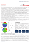
1
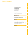
precisioN Knee Navigation
Operative Technique
precisioN Knee Software
Operative Technique
Introduction
The Stryker® Navigation System
– precisioN Knee module is an
interactive operative monitoring
system designed to improve the surgical
performance and clinical outcome of
knee replacement surgery.
As a PC-based, imageless guidance
system, the Stryker Knee Navigation
System helps to facilitate improved
decision making for alignment and
orientation of instruments, trials and
implants as well as for balancing soft
tissue.
Furthermore, the Stryker Knee
Navigation System provides surgeons
with pre-operative, intra-operative and
post-implantation assessments of the
patient’s joint kinematics and various
documentation options.
Long term cost savings may result
from possible shorter hospital stays,
decreased morbidity and blood loss,
improved joint stability and decreased
rehabilitation time.1
Acknowledgement
Knute Buehler, M.D.
Chief of Arthritis and Joint
Reconstruction
The Center - Orthopedic and
Neurosurgery Care and Research
Bend, Oregon
USA
Important Notice
Only trained medical personnel may use
the Stryker Navigation System. As with any
technical guide, the surgeon should consider the
particular condition of the patient and perform
the necessary adjustments, if required. Stryker®
precisioN Knee module is not a replacement
for the surgeon’s qualification, expertise, or
judgement.
Safety and caution notes should be carefully
reviewed prior to proceeding. For the required
safety information and contraindications, please
refer to the Safety Information, supplied with
the precisioN Knee software package, and to the
Special appreciation is expressed to Dr.
Knute Buehler for his direct assistance
with the development of this Operative
Technique, and many thanks to the
other esteemed surgeons who assisted
in the development and validation of
the precisioN Knee product.
Instructions For Use, supplied with the system
components.
For a detailed description of the software features
and procedures, and for a comprehensive
definition of the computed mechanical axes and
resection levels, refer to the online User Manual
for the precisioN Knee software.
For information related to the use of
conventional instrumentation, please refer
to the operative techniques and the user
documentation supplied with each company’s
conventional instrumentation.
The Stryker precisioN Knee software,
as well as the dedicated instruments,
are compatible and represent an open
platform for different implant systems.
1)
J.M. Sikorski, S. Chauhan: Aspects of Current
Management, Computer Assisted Orthopedic
Surgery: Do We Need CAOS?, JBJS(Br) Vol. 85-B,
No. 3, April 2003
1 System and Software
Set Up
Table of Contents
2 Patient Preparation
6
3 Patient Registration
8
4 Reference System
16
5 Verify Registration/ Analyze Initial Alignment
18
6 Resect Bones
19
7 Analyze Trial and Final Alignment
24
3 Patient Registration
4
4 Reference System
1 System and Software Set Up
2 Patient Preparation
Operative Technique
8 Automatic Sizing and Implant Positioning
5 Verify Registration/
Analyze Initial Alignment
Advanced Features
26
9 Additional Options - Miscellaneous
36
10 Part List
38
7 Analyze Trial and Final
Alignment
35
8 Advanced Features
9 Additional Options - Documentation Tools
9 Additional Options
34
10 Part List
9 Additional Options - Gap Monitoring
6 Resect Bones
Appendix
1 System and Software
Set Up
Operative Technique
1 System and Software Set Up
System Start Up
Note:
The system and software set up can
be completed by the OR support
staff prior to operation.
To ensure instrument visibility,
place the system opposite of the
surgeon.
Plug in the main power cable of
the navigation system.
Press the main power button on
the front panel of the navigation
system.
Enter the user name (navigation)
and press enter or use the left
mouse button and click “OK”.
Upon Application Manager
start up, use the mouse to select
“precisioN Knee Navigation”.
1 System and Software
Set Up
1 System and Software Set Up
Software and Tool
Preparation
Enter Patient Data
Select the “Enter Patient Data”
screen.
Record the patient’s first and last
name.
Indicate the leg side undergoing
treatment.
Entering the patient’s name and
indicating the leg side is mandatory.
Click “Next” to proceed.
Prepare and Initialize Tools
The required tools are listed in the
Setup System dialog.
Load sterile batteries into the
navigated tools.
One sterile battery will be needed for
each tool used.
To initialize the navigated tools
Face the LEDs towards the camera
and press and hold the SELECT
button on the tool for 2-3 seconds.
Tool initialization is confirmed by an
audible alert and a checkmark in front
of the software button.
Upon pointer initialization, the
“Validate Pointer” pop-up window
appears.
Validate Pointer
With the pointer validation, the
accuracy of the pointer tip is
calibrated.
Touch the center of any one of the
tracker’s validation discs with the
pointer tip and press the SELECT
button on the pointer for 2-3
seconds to validate.
2 Patient Preparation
Operative Technique
2 Patient Preparation
Incision
Standard and minimally invasive
techniques for exposing the knee
joint can be applied and are
supported by the Stryker Knee
Navigation System.
Patient Anchoring
The patient trackers must be rigidly
fixated to femur and tibia of the leg
undergoing treatment.
For tracker fixation two kinds of
anchoring devices are available:
OrthoLock™ anchoring device
Bi-cortical Anchoring Pins
OrthoLock™ anchoring device
OrthoLock™ can be used for standard
and minimally invasive TKA.
Bi-cortical Anchoring Pins
Bi-cortical Anchoring Pins can
be used for standard TKA with
conventional or dedicated cutting
guides.
For Anchoring Pin fixation refer to the
chapter “Additional Options”.
2 Patient Preparation
2 Patient Preparation
OrthoLock™ Fixation
The OrthoLock™ can be used in
conjunction with OrthoLock™ Exand Navigation Pins.
For fixation, a minimum of 2 pins
are needed.
OrthoLock™ may be fixated prior to
inflating tourniquet cuff.
To provide sufficient stability, the pins
can be fixated bi-cortically.
On the femur, the pins are positioned
close to the knee joint. To minimize
muscle load, pins are placed with the
knee in flexion.
On the tibia, the pins can be
positioned distal of the tibial tubercle
to avoid the patella tendon and
collisions with the tibial implant.
Note:
For bi-cortical fixation, only engage
the second cortex.
To help prevent drilling through the
bone, stop pin insertion as soon as
the pin penetrates the second cortex.
Avoid pin positions and pin
orientations where any vulnerable
neurovascular structures might
be injured both at entry and exit
points.Avoid pin collisions with the
implants and any external checks,
alignment or resection guides which
may be utilized.
Mount Patient Tracker
After anchoring device fixation is
complete
Mount the patient trackers to
the femoral and tibial anchoring
device.
Operative Technique
3 Patient Registration
Registration
3 Patient Registration
With registration, the positions of
anatomical landmarks and axes
are digitized as reference for the
alignment of instruments, bone cuts
and leg.
Position the Camera
Before starting with patient
registration
Bring the camera in line with the
knee joint so that all instruments
are centered in the working
volume signified by the grey circles
in the “Setup System” dialog.
Select the Next button to proceed
with the “Register Femur” dialog.
Confirm Treatment
Prior to femur registration
Confirm the treatment and
selected leg side by pressing the
SELECT button of any navigated
tool that is visible to the camera.
3 Patient Registration
Femur Registration
3 Patient Registration
By digitizing femoral landmarks,
the following axes and references are
defined:
Mechanical femur axis
Femoral rotation axis
Reference for resection level
Reference for notching
Hip in Flexion
Flex hip at any angle and press the
SELECT button on either patient
tracker to record.
Hip Center
Slowly and smoothly circumduct
the hip with changing radii.
During rotation, avoid pelvic
movement.
As soon as a sufficient number of
points are recorded, the software
automatically stops recording.
Note:
Avoid moving the camera or the
OR table during motion analysis.
Camera or OR table movement could
compromise the calculation of the
hip center or cause the software to
reject the calculation.
Note:
In case of pelvic movement, have
the assistant stabilize the pelvis and
repeat range of motion.
Operative Technique
3 Patient Registration
3 Patient Registration
Medial Epicondyle
Place the pointer’s tip into the
sulcus of the medial epicondyle
and press the pointer’s SELECT
button to record.
Lateral Epicondyle
Place the pointer’s tip onto the
most prominent point of the
lateral epicondyle and press the
pointer’s SELECT button to
record.
10
3 Patient Registration
Place the pointer’s tip at the
center of the trochlear sulcus
anterior toward the distal end of
the femoral shaft and press the
pointer’s SELECT button to record.
This is essentially where one would
place the IM rod when using
conventional instrumentation.
3 Patient Registration
Femur Center
Femoral AP Axis
Align the pointer’s axis with
the most posterior point of the
trochlea and the most anterior
point of the intercondylar fossa,
also referred to as Whiteside’s line.
Press the pointer’s SELECT button
to record.
11
Operative Technique
3 Patient Registration
3 Patient Registration
Medial Distal Condyle
Place the pointer’s tip onto
the medial condyle and begin
digitizing by pressing the pointer’s
SELECT button and moving the
tip over the surface of the medial
condyle in a zig-zag painting
fashion.
Note:
Ensure that the most distal aspect
of the condyle has been included
and that the pointer has not left
the surface of the bone during
digitizaton.
Lateral Distal Condyle
For lateral distal condyle
digitization, follow the instructions
provided above for the medial side.
Anterior Cortex
Place the pointer’s tip onto
the anterior cortex and begin
digitizing by pressing the pointer’s
SELECT button and moving the
tip on the anterior cortex in a
painting fashion.
During point acquisition
Include the most prominent
anterior region and the expected
saw blade exit points.
Select “Next” to proceed to the
“Register Tibia” dialog.
12
3 Patient Registration
By digitizing tibial landmarks, the
following axes and references are
defined:
Mechanical tibia axis
Tibial rotation axis
Reference for resection level
3 Patient Registration
Tibia Registration
Tibia Center
Place the pointer’s tip onto the
middle of the interspinous sulcus
anteriorly near the anterior mid
footprint of the ACL attachment
and press the pointer’s SELECT
button to record.
Tibial AP Axis
Align the pointer’s axis with the
midpoint of the posterior cruciate
ligament and the medial third of
the tibial tuberosity.
Press the pointer’s SELECT button
to define and record a neutral
tibial AP axis.
13
Operative Technique
3 Patient Registration
3 Patient Registration
Medial Compartment
Place the pointer’s tip onto the
medial compartment and begin
digitizing by pressing the pointer’s
SELECT button and moving the
tip over the surface of the medial
compartment in a painting
fashion.
Note:
Ensure the lowest aspect of the
compartment has been included.
Avoid digitizing below the lowest
anatomical point to avoid a false
survey reading.
Lateral Compartment
For lateral compartment digitization
follow the instructions provided above
for the medial compartment.
14
3 Patient Registration
Place the pointer’s
tip onto the most
prominent aspect of
the medial malleolus
and press the pointer’s
SELECT button to
record.
3 Patient Registration
Medial Malleolus
Lateral Malleolus
Place the pointer’s tip onto the
most prominent aspect of the
lateral malleolus and press the
pointer’s SELECT button to record.
Select “Next” to proceed to the “Verify
Registration” dialog.
15
Operative Technique
4 Reference System
Reference System
Upon completion of femur and tibia
registration, the reference system is
defined.
The digitized reference landmarks
and axes are now used to assess the
kinematics and for calculating the
alignment of instruments and bone
cuts.
4 Reference System
Reference for Varus/ Valgus,
Flexion/ Extension or Slope
Hip center
With Stryker Navigation, the femur
reference for varus/ valgus and flexion/
extension is the mechanical femur axis
defined by the digitized
Hip center, and
Knee center
Femur center
Tibia Center
The tibia reference for varus/ valgus
and slope is the mechanical tibia axis
defined by the digitized
Tibia center, and
Calculated ankle center
The ankle center is calculated by
dividing the digitized transmalleolar
axis according to the ratio of 56%
lateral to 44% medial.
Ankle center
Medial
malleolus
16
Lateral malleolus
Note:
With precisioN Knee software, the
anatomical axis of femur and tibia
is not taken into consideration.
4 Reference System
Reference for Rotation
Reference for femoral rotation is the
averaged rotation axis defined and
calculated by the digitized
Reference for tibial rotation is the
digitized
Tibial AP axis
Note:
4 Reference System
Transepicondylar axis (medial and
lateral epicondyle), and
Femoral AP axis
With the precisioN knee software,
the posterior condylar line is not
taken into consideration as reference
for femoral rotation.
Reference for Resection Level
Reference for the distal femur
resection level is the most prominent
distal point of the digitized condyle.
Reference for the proximal tibia
resection level is the most recessed
point of the digitized compartment.
The system calculates the length of
the perpendicular line from the
reference point to the resection plane.
17
Operative Technique
5 Verify Registration/
Analyze Initial Alignment
Verify Registration/ Analyze
Initial Alignment
The “Verify Registration” screen
enables the surgeon to check the
digitized mechanical axes for
plausibility and to analyze initial leg
alignment with respect to:
5 Verify Registration/
Analyze Initial Alignment
ROM
Varus/ valgus misalignment and
laxity
Flexion contracture or
hyperextension
For analysis
Bring the leg through a range of
motion and apply varus and valgus
stress.
For documentation, initial alignment
can be recorded.
Highlight and select “Next” to
proceed.
Analyze Initial Varus-Valgus
With the “Analyze Varus-Valgus”
screen the varus/ valgus deformity
and laxity of the knee joint
throughout a whole range of motion
can be assessed.
The graph with the blue slider bars
indicates the amount of varus/
valgus laxity and deformity with
respect to the flexion angle.
To record the graph
Activate the record button and
perform a range of motion exercise
at least twice while applying both
varus and valgus load.
Press the SELECT button on any
tracker to stop recording.
Highlight and select “Next” to proceed
with navigating the bone cuts.
18
6 Resect Bones
Resect Bones - Options
Workflow Options
Both posterior and anterior
referencing techniques are
supported by the Stryker precisioN
Knee software.
Additionally, two software control
options for navigating bone cuts are
offered:
Manual Workflow
With the manual workflow,
the bone cut sequence can be
configured and is displayed on
sequential screens.
Reactive Workflow
With the reactive workflow, the
software selects the navigation
screens automatically. Reactive
screen selection is based upon
trackers’ position and alignment.
The posterior referencing workflow
is described in the following
chapters.
Dedicated Mini Jig
6 Resect Bones
Note:
Hardware Options
For distal femur and proximal tibia
cuts, two different kinds of cutting
blocks can be navigated:
Conventional cutting blocks
Conventional cutting blocks
with intramedullary fixation are
navigated by inserting a Resection
Plane Probe with a tracker into the
cutting slot.
Navigated resection guides
The Dedicated Mini Jig and the
Navigated MIS Jig shown here do
not require intramedullary fixation
and are equipped with a dedicated
tracker interface.
Navigated MIS Jig
19
Operative Technique
6 Resect Bones
Resect Distal Femur
When using the Dedicated Mini Jig
Bring the cutting guide into
position, fixate it to the distal
femur and attach the blue tibial
tracker, or tool tracker, to the
tracker interface.
With the Reactive Workflow feature,
the software automatically selects the
“Resect Distal Femur” dialog.
On the screen, the yellow disc
represents the actual cutting block’s
saw capture position. Additionally, the
varus/ valgus and flexion/ extension
alignment as well as the medial and
lateral resection depth is numerically
displayed.
6 Resect Bones
Align and fix the cutting block to
desired parameters on the bone
with headless pins.
After proper cutting block fixation,
the adjustment component and
fixation plate can be removed and the
distal femur can be resected.
Verify Distal Femur Cut
For cut verification and
documentation,
Attach tibial tracker, or tool
tracker, to the Resection Plane
Probe.
Hold the plane probe flush against
the cut.
Make sure the “Record Cut”
button is highlighted and press the
SELECT button on the tracker to
record.
Note:
For detailed instructions
on how to use dedicated
cutting guides refer to
the IFU supplied with the
product and the Operative
Technique for Navigated
Resection Guides
(Lit. no: 9100-091-000).
20
6 Resect Bones
Align Femoral Rotation
Position the AP Sizer flat against
the distal femur cut.
When using AP Sizer with size specific
slots
Slide the Resection Plane Probe
with the attached tibial tracker,
or tool tracker, into the slot of the
predicted size.
For AP Sizer without size specific slots
Put the Resection Plane Probe
onto any flat surface parallel to the
anterior cutting plane.
The yellow lines represent the AP Sizer
rotation. The rotation is displayed as
a numerical value with respect to the
averaged rotation axis, digitized AP
axis, and transepicondylar line.
Align the rotation of the AP Sizer.
6 Resect Bones
With the Reactive Workflow feature,
the software automatically selects the
“Align Femoral Rotation” screen.
If the Resection Plane probe sits in the
slot of the predicted size
Check for potential notching.
Upon proper alignment
Fixate the AP Sizer and re-check
the alignment.
With the AP Sizer fixed, the peg holes
can be drilled. The 4-in-1 cutting
block can be impacted into these holes
and the remaining four femoral bone
resections can be completed.
For anterior cut verification and
documentation
Hold the Resection Plane Probe
with tibial tracker, or tool tracker,
flush against the anterior cut,
make sure the “Record Rotation”
button is highlighted, and press the
SELECT button on the tracker to
record.
21
Operative Technique
6 Resect Bones
Resect Proximal Tibia
When using the Dedicated Mini Jig
Bring the cutting block into
position, fixate it to the tibia, and
attach the green femoral tracker,
or tool tracker, to the tracker
interface.
With the Reactive Workflow feature,
the software automatically selects the
“Resect Proximal Tibia” dialog.
On the screen, the yellow disc
represents the actual cutting block’s
saw capture position.
Additionally, the varus/ valgus
alignment, slope, and medial/ lateral
resection depth are displayed as a
numerical value.
6 Resect Bones
Align and fix the cutting guide to
desired parameters on the bone
with headless pins.
After proper cutting block fixation,
the adjustment component and
fixation plate can be removed and
the proximal tibia can be resected.
Verify Proximal Tibia Cut
For proximal tibia cut verification and
documentation
Attach the femoral tracker, or tool
tracker, to the Resection Plane
Probe and hold the plane probe
flush against the cut.
Make sure the “Record Cut”
button is highlighted and press the
SELECT button on the tracker to
record the cut.
Note:
For detailed instructions on
how to use dedicated cutting
guides refer to the IFU
supplied with the product and
the Operative Technique for
Navigated Resection Guides
(Lit. no: 9100-091-000).
22
6 Resect Bones
Soft Tissue Balancing
Within the Reactive Workflow feature,
an “Analyze Alignment” screen is
integrated to help control soft tissue
balancing.
Attach femoral and tibial tracker to
the anchoring devices.
With the Reactive Workflow feature,
the software automatically selects the
“Analyze Alignment” screen.
Distract the knee joint and perform
sequential soft tissue releases until
the desired varus/ valgus balance is
achieved.
Align Tibial Rotation
6 Resect Bones
For Stryker implants
Attach the femoral tracker, or
tool tracker, to dedicated Tibial
Alignment Handle and use the
alignment handle to position the
tibial template onto the resected
tibial plateau.
With the Reactive Workflow feature,
the software automatically selects the
“Align Tibial Rotation” screen.
On the software screen, the yellow
cross represents the actual template
rotation. Additionally, the rotational
alignment is displayed as a numerical
value.
Align the tibial template properly
and pin the template into position.
To record the template position
Make sure the “Record Rotation”
button is highlighted and press the
SELECT button on the tracker.
Note:
To proceed with analyzing the intraoperative leg alignment, highlight
“Next” and press the SELECT button
on any tool.
When using a non-Stryker Alignment
Handle, the femoral tracker, or tool
tracker, can be attached to the square
Resection Plane Probe and held
against the handle. Make sure the
tracker is in line with the handle’s
axis and the Resection Plane Probe
parallel to the tibial template.
23
Operative Technique
7 Analyze Trial and Final Alignment
Analyze Trial Alignment
The “Analyze Trial Alignment”
screen is similar to “Verify
Registration”.
It enables the surgeon to assess the
intra-operative leg alignment and
ROM with the trial implants in
place.
The result of soft tissue balancing
and comparisons between tibial
inlays, range of motion and leg
alignment can be controlled and
adjusted.
7 Analyze Trial and Final
Alignment
For documentation, intra-operative
alignment can be recorded.
24
7 Analyze Trial and Final Alignment
Analyze Trial Varus Valgus
The “Analyze Trial Varus/ Valgus”
screen is similar to “Analyze Initial
Varus/ Valgus”.
It enables the surgeon to assess the
varus/ valgus alignment and the
stability of the knee joint with the
trial implants in place.
Analyze Final Alignment
After final prosthesis implantation,
an outcome assessment can be
performed.
7 Analyze Trial and Final
Alignment
For the outcome assessment,
the same screen types are used
as in “Analyze Initial and Trial
Alignment”.
25
Advanced Features
8 Automatic Sizing and Implant
Positioning
Automatic Sizing and
Implant Positioning
Automatic femoral implant sizing
and positioning can be enabled in
the user settings for the following
Stryker® implant families and types:
Triathlon™ (CR and PS)
Scorpio® (CR and PS)
Scorpio® NRG (CR and PS)
Based on the selected implant family
and the digitized axes and bone
morphology, the software calculates
the optimal size and position of the
femoral implant.
The goal of the calculations is to
achieve the best anterior match while
keeping the implant size as small as
possible.
Unlike the standard patient
registration workflow, automatic
implant sizing and positioning
requires
a specific
anterior
cortex
Screenshot
Medial
Posterior
digitization
and
additional
surface
Condyle
mapping of the posterior condyles.
Note:
The calculations are based on the
digitized axes and digitized bone
morphology only. The soft tissue
conditions are not considered.
8 Advanced Features
Medial/ Lateral Posterior
Condyle
Place the pointer’s tip onto the
medial posterior condyle and begin
digitizing by pressing the pointer’s
SELECT button and moving the
tip over the surface of the medial
posterior condyle.
Repeat this procedure for the
lateral posterior condyle.
Note:
Ensure that the most posterior aspect
of the condyle has been included and
that the pointer’s tip does not digitize
false points in the air at the back of
the knee.
26
8 Automatic Sizing and Implant Positioning
Anterior Cortex
For automatic sizing and implant
positioning, adequate digitization of
the anterior cortex has to be ensured.
To provide guidance, a digitization
grid and the proximal implant
contours of every second implant size
are superimposed on the bone model.
The proximal implant contours are
derived from the implant database.
Their positions are determined by the
digitized landmarks.
The proximal implant contours
define the area of the anterior cortex
most important for an optimized and
enhanced anterior implant match. In
addition, the contours determine size
specific digitization regions.
When digitizing, the software will
“check off” and change the color of
the size specific digitization regions
once the minimum amount of points
have been obtained for that region
and implant size.
Note:
For the software to be able to properly calculate
the optimal size and best anterior match,
the following must be ensured: The relevant
portions of the anterior cortex must be covered
and the digitization must represent the bone
morphology properly. Uneven point distribution
and uneven mapping density should be avoided.
The digitized points should cover an area
reaching at least 12 mm proximal to the final
implant.
8 Advanced Features
Place the pointer’s tip onto
the anterior cortex and begin
digitizing by pressing the pointer’s
SELECT button and moving the
tip over the surface of the anterior
cortex.
After digitization, potential air points
are displayed by the software and can
be deleted.
Select “Next” to proceed.
27
Advanced Features
8 Automatic Sizing and Implant
Positioning
Position Implant
After completion of patient
registration, the software will
calculate the size and position for the
best fitting implant and place it on
the virtual femur.
For verification, the following
calculated parameters are displayed
graphically and in numerical value in
the “Position Implant” dialog:
Femoral implant size
Flexion angle
Medial & lateral distal resection
level
Medial & lateral posterior
resection level
AP shift (if applicable)
Uncovered anterior bone
resection (area marked in orange)
Maximum gap between implant
and the anterior cortex and
its position (orange dot) (if
applicable)
Varus/ valgus and rotational
alignment, as well as the
reconstruction of the posterior
and distal condyles are achieved in
accordance with the principles of
conventional surgical technique.
8 Advanced Features
The calculated parameters are either
displayed within the bone model
or in the numerical value boxes in
grey (see the highlighted area in the
screenshot).
In addition to the calculations, the
dialog provides online information
on the actual leg alignment and,
if selected in the user settings, a
preview on the size of the flexion and
extension gap.
Verify the calculated femoral
implant size and position.
Select “Next” to open the
“Planned Femoral Implant” dialog
summarizing size, alignment and
position of the calculated femoral
implant.
Select “OK” to proceed.
28
8 Automatic Sizing and Implant Positioning
If soft tissue constraints require, the
calculated implant can be quickly
virtually downsized to visualize the
result of using a smaller femoral
component instead of the suggested
one, or, if desired, a more in depth
implant modification dialog may be
entered.
Select “Downsize to …” or
“Modifiy Implant Position …”.
8 Advanced Features
The calculated parameters are
displayed in the “Resect Distal Femur”
and “Align Femoral Rotation” dialog
in grey numerical values, suggesting
the target for instrument alignment.
In addition, the suggested resection
levels are displayed as green planes.
29
Advanced Features
8 Automatic Sizing and Implant
Positioning
Implant Modification - Option 1:
Downsize to …
The “Downsize Implant” dialog
facilitates downsizing the calculated
implant to the next smaller one.
Keep Anterior
To downsize the calculated implant
Select which (resection) plane
shall be kept in position when
downsizing the calculated implant:
- Anterior resection plane
- Posterior resection plane
- Implant center line
Select the desired flexion angle of
the downsized femoral implant.
Select “Downsize”.
Keep Posterior
Implant Modification - Option 2:
Modify Implant Position …
8 Advanced Features
Use Average
The “Modify Implant Position”
dialog allows to manually adjust the
suggested femoral implant position
with respect to
Varus/ valgus
Proximal- distal shift (Resection
level)
External/ internal rotation
Anterior/ posterior shift
Flexion/ extension
Size
When modifying the implant size
and position, orange marked areas
indicate uncovered anterior bone
resection. If applicable, an orange
dot displays the position of the
maximum gap between implant and
anterior cortex.
In case of notching, a warning
message is displayed.
To modify the implant position or size
Select the arrow control buttons.
To close the “Modify Implant Position”
screen
Select “OK”.
30
8 Automatic Sizing and Implant Positioning
Automatic Sizing and Implant Positioning - Calculations
Optimal femoral implant size
and position is calculated in the
following manner:
First, the software virtually
positions the smallest implant size
on the digitized femur.
For positioning, varus/ valgus and
rotational alignment are set to 0°.
The distal and posterior condyles
are reconstructed in accordance
to the principles of conventional
surgical technique.
After positioning the smallest
implant size, the software iterates
this process for all available implant
sizes. In addition, different flexion
angles as well as AP shift are
applied.
Within these iterations, the
software selects the femoral implant
size and position which fits the
following (prioritized) criteria best:
Implant Sizing and Positioning - Iterations
1.Position smallest implant and
assess fit
2.Apply flexion (1° to 5°)
3.Assess fit (for each flexion)
4.Apply AP shif t (for each
flexion)
5.Assess fit
1a. Select next bigger size ...
... and assess fit
2a. Apply flexion (1° to 5°)
3a. Assess fit ...
Implant Sizing and Positioning - Criteria for Best Fit
1
2
3
4
8 Advanced Features
1. Maximum run out of uncovered
anterior cortex resection is
smaller than 12 mm.
2. Minimum 1% of the proximal
implant contour is lying on or
above uncut anterior cortex.
3. Minimum 60% of the proximal
implant contour has contact
with cut anterior cortex.
4. Maximum gap between the
proximal implant contour and
uncut anterior cortex bone is
smaller than 1.5 mm.
31
Advanced Features
8 Automatic Sizing and Implant
Positioning
Notching
1
2
The software indicates notching if
one of the following criteria applies:
1. Maximum run out of uncovered
anterior cortex resection is larger
than 12 mm.
2. Entire proximal implant contour
has contact with cut anterior
cortex.
Maximum Gap between Proximal
Implant Contour and Anterior
Cortex Bone
8 Advanced Features
A gap between the proximal implant
contour and anterior cortex is
calculated by the software. The gap
is measured at its maximum in the
sagittal plane perpendicular to the
digitized mechanical femur axis.
Estimate Medial Condyle for
Varus Knees
With the “Estimate medial condyle
for varus knees” feature activated,
the software alerts the user if the
digitized lateral condyle is more
prominent than the medial side.
With the alert, the software offers
an estimation of the original medial
condyle or to continue with the
more prominent lateral condyle as
reference for distal femur resection
level and for calculating the best
fitting implant.
32
8 Automatic Sizing and Implant Positioning
Automatic Sizing and Implant Positioning - Options
Detect ML Overhang
The “Detect ML Overhang”
functionality can be enabled in the
user settings.
It requires the digitization of the
medial and lateral overhang region.
In the “Position Implant” dialog the
average medial/ lateral overhang or
uncovered bone cut will be displayed
in numerical value.
The amount of overhang or
uncovered bone is measured at the
AP position of the digitized overhang
region.
Note:
Potential medial/ lateral overhang
or uncovered bone cut is displayed
only. It is not considered in the
automatic sizing and positioning
calculations.
Navigated Drill Templates for AP
alignment are available for Stryker
Triathlon™, Scorpio® and Scorpio®
NRG implant systems.
Navigated drill templates can be
selected in the user settings, if
automatic sizing is enabled.
They can be used to prepare the
rotational alignment and AP position
of the 4-in-1 cutting block.
The navigated drill templates can
replace the conventional AP sizer.
8 Advanced Features
Navigated Drill Template for AP
Alignment
With the navigated drill template, an
additional frontal view of the anterior
cortex is displayed.
The anterior cortex view gives a
preview of the position and size of
the uncovered bone resection against
the given flexion/ extension of the
distal femur cut and the AP implant
position.
33
Appendix
9 Additional Options - Gap Monitoring
Gap Monitoring
Gap monitoring enables the surgeon
to analyze the size of the flexion/
extension gap based upon the
recorded bone resections.
Gap monitoring can be enabled in
the User Preferences menu.
For Gap Monitoring, it is mandatory to
Record the distal femur cut,
Record the proximal tibia cut, and
Record the posterior femur cut.
Note:
The posterior femur cut must be
recorded by using the Posterior
Plane Probe.
For gap assessment
Attach both trackers to the
anchoring device.
With the Reactive Workflow feature,
the software automatically selects the
“Analyze Alignment” screen.
Distract the knee in extension to
assess the size of the extension gap.
Distract the knee in flexion to
assess the size of the flexion gap.
9 Additional Options
Depending on the result, additional
measures such as ligament or capsule
release may be applied to achieve an
equal gap in flexion and extension.
34
9 Additional Options - Documentation Tools
Documentation Tools
Screenshot
The screenshot feature allows
for intraoperative navigation
screenshots. The screenshots can be
used to illustrate lectures, research
papers, articles or promotion
materials.
The screenshots are stored in the PNG
format on hard drive D:\KneeData\
patients\...
To create a screenshot
Highlight and select the screenshot button.
Ruler
Located on all navigation screens,
is a universal measurement tool
enabling the surgeon to perform
and document the required
measurements.
To activate the dialog
Select the ruler button,
Select whether the distance is
measured on the femur or tibia,
Digitize two points.
Upon digitization of the two points,
the overall distance as well as the
medial-lateral, anterior-posterior, and
proximal-distal distance is calculated.
The report is automatically created
after saving the patient file.
It compiles all relevant surgery data
including the recorded positions
of the cutting planes and all
kinematics data.
9 Additional Options
Report
The report is saved as a pdf file
on the hard drive D:\KneeData\
patients\... and can be accessed via
the main menu.
35
Appendix
9 Additional Options - Miscellaneous
Bi-cortical Anchoring Pin
Fixation, Position and
Orientation
Bi-cortical Anchoring Pins are
two step pins available in different
thread diameters and lengths.
Rotational stability of bi-cortical
Anchoring Pins is provided by the
pins’ bone anchor splines.
On the femur, the Anchoring Pin can be
positioned within the incision in a region
of the metaphysis.
On the tibia, the Anchoring Pin can be
inserted in the midportion of the bone
and distal to the tibial tubercle to avoid
collision with the tibial cutting guide
and the keel of the implant.
Note:
Avoid pin positions and pin
orientations where any vulnerable
neurovascular structures might be
injured on either side of the entrance
or exit points.
Choose an Anchoring Pin with
the appropriate thread length
according to the insertion depth.
For fixation, pre-drill a pilot hole with a
3.2mm drill.
The pin can be inserted bi-cortically,
using the Insertion Tool.
Record Initial Table/ Record
Trial Table/ Record Final Table
The “Record Table” screen
automatically documents the
kinematic data (flexion/ extension,
varus/ valgus, rotation) at specific
flexion angles throughout the whole
range of motion.
9 Additional Options
If selected in the User Preferences,
the Record Table feature is part of
the Analyze Initial and Trial and
Final Alignment sequences.
36
Appendix
9 Additional Options - Miscellaneous
Anterior Referencing
Stryker® precisioN Knee software
supports the posterior as well as
the anterior referencing bone cut
sequence.
If anterior referencing is selected in
the user settings, the “Align Femoral
Rotation” dialog is expanded and
displays the rotational and the
flexion/ extension alignment of the
anterior cutting plane.
HTO Workflow
With Stryker® precisioN Knee
software, a HTO workflow
supporting the assessment of the
overall leg alignment can be enabled.
For HTO navigation the following
landmarks have to be digitized:
Hip in flexion
Hip center
Femur center
Femoral AP axis
Tibia center
Tibial AP axis
Medial/ lateral malleolus
Hotspot Landmark Redigitization
To open the hotspot redigitization
dialog
Move the pointer tip close to the
landmark.
The deviation of the newly defined
landmark or axis to the previous
registration will be displayed.
9 Additional Options
During navigation and alignment
analysis, the following landmarks
can be redefined by hotspot
redigitization:
Medial/ lateral epicondyle
Femoral AP axis
Tibial AP axis
Select “Redigitize” to redigitize the
landmark or axis.
37
Appendix
10 Part List
Part Number
Description
Anchoring Devices
6007-4xx-000 Anchoring Pins 4 mm x 20/ 25/ …/
60 mm
6007-5xx-000 Anchoring Pins 5 mm x 30/ 40/ 50 mm
6007-015-000 Insertion Tool (for Anchoring Pins)
6007-003-000 OrthoLock™
6007-10x-xxx
OrthoLock™ EX-Pins 3x110/ 4x150 mm
6007-00x-xxx Navigation Pins 3x100/ 3x150/ 4x100 mm
Navigation Hardware
Note: Resection Plane Probes are available
for slots from 0.9 mm to 1.5 mm.
6003-175-000
Pivotal©
6003-027-000
Resection Plane Probe – Slots 1.3 mm 1
6003-028-000
Resection Plane Probe – Round
6003-070-000
Posterior Plane Probe
6003-100-110
Universal Joint Screwdriver 2
6003-100-100
Screwdriver 2
6003-250-000
Pivotal© Tracker AP Sizer Interface
6541-002-808
Navigated Tibial Alignment Handle
6541-005-610
MIS Femoral Navigated Stylus
6541-004-401
Navigated Tracker Adapter Triathlon
8001-0315
Navigated Drill Template - Scorpio
6541-1-688
Navigated Drill Template - Triathlon
Alignment Handle
1)
Note: Screwdriver required for
OrthoLock™, Navigated MIS Jig and
Dedicated Mini Jig.
2)
38
Accessories
6000-006-000
Instrument Battery
10 Part List
Description
Part Number
Software
precisioN Knee Navigation
6003-640-000
Navigation Platform
Navigation System II - Cart
7700-100-000
eNlite
7700-300-000
Navigated Tools
Ortho Grip Knee Pointer
6003-012-000
Tibia/ Pelvis Tracker
6003-005-000
Femur Tracker
6003-010-000
Universal Tracker (optional)
6000-005-000
Dedicated Mini Jig
Adjustment Component
6003-100-020
Mini Fixation Plate
6003-300-020
Mini Cutting Guide
6003-300-010
Tracker Adapter
6003-100-090
Navigated MIS Jig A
6003-200-010
Navigated MIS Jig B
6003-200-020
Tracker Adapter
6003-200-030
10 Part List
Navigated MIS Jig
39
Stryker SA
Cité Centre
Grand-Rue 90
1820 Montreux
Switzerland
t: +41 21 966 12 01
f: +41 21 966 12 00
www.europe.stryker.com
Solely for use by Healthcare Professional.
The productslisted above are CE marked according to the MedicalDevice Directive 93/42/EEC.
The information presented in this brochure is intended to demonstrate a Stryker product. Always refer to the
package insert, product label and/or user instructions before using any Stryker product. Products may not be
available in all markets. Product availability is subject to the regulatory or medical practices that govern individual
markets. Please contact your Stryker representative if you have questions about the availability of Stryker products
in your area.
Products referenced with ™ designation are trademarks of Stryker.
Products referenced with ® designation are registered trademarks of Stryker.
Literature Number: MTX9100001117
MTX/GS 10/07
Copyright © 2007 Stryker